Language selection

Search

Patent 2841949 Summary

Third-party information liability

Some of the information on this Web page has been provided by external sources. The Government of Canada is not responsible for the accuracy, reliability or currency of the information supplied by external sources. Users wishing to rely upon this information should consult directly with the source of the information. Content provided by external sources is not subject to official languages, privacy and accessibility requirements.

Claims and Abstract availability

Any discrepancies in the text and image of the Claims and Abstract are due to differing posting times. Text of the Claims and Abstract are posted:

  • At the time the application is open to public inspection;
  • At the time of issue of the patent (grant).
(12) Patent: (11) CA 2841949
(54) English Title: PIPE ANCHOR
(54) French Title: ANCRAGE DE TUYAU
Status: Granted
Bibliographic Data
(51) International Patent Classification (IPC):
  • F16L 59/135 (2006.01)
  • F16L 3/00 (2006.01)
  • F16L 59/14 (2006.01)
(72) Inventors :
  • ZAGORSKI, KENNETH (United States of America)
  • DONOGHUE, JOSEPH A. (United States of America)
  • BOCK, MICHAEL E. (United States of America)
(73) Owners :
  • RILCO MANUFACTURING COMPANY, INC. (United States of America)
(71) Applicants :
  • RILCO MANUFACTURING COMPANY, INC. (United States of America)
(74) Agent: BERESKIN & PARR LLP/S.E.N.C.R.L.,S.R.L.
(74) Associate agent:
(45) Issued: 2020-06-02
(86) PCT Filing Date: 2012-07-11
(87) Open to Public Inspection: 2013-03-07
Examination requested: 2017-07-04
Availability of licence: N/A
(25) Language of filing: English

Patent Cooperation Treaty (PCT): Yes
(86) PCT Filing Number: PCT/US2012/046157
(87) International Publication Number: WO2013/032583
(85) National Entry: 2014-01-14

(30) Application Priority Data:
Application No. Country/Territory Date
13/219,206 United States of America 2011-08-26

Abstracts

English Abstract

A pipe anchor is disclosed having a pipe trunnion stop for attaching to an outer surface of a pipe by welding. A mating top cradle and bottom cradle generally encircle and hold a length of the pipe. The bottom cradle has a pass-through to accommodate the pipe trunnion stop. There is a base onto which the bottom cradle sets, the base includes a void into which the pipe trunnion is secured. An insulation layer is positioned between the pipe and the top cradle and bottom cradle, and around the pipe trunnion stop, A bolting assembly on the top cradle portion and a mating bolting assembly on the bottom cradle portion secures the top cradle portion and the bottom cradle portion to each other. Another embodiment includes multiple pipe trunnion stops along with respective pass-through and base void sections.


French Abstract

L'invention porte sur un ancrage de tuyau qui présente un arrêt de tourillon de tuyau devant être attaché à une surface externe d'un tuyau par soudage. Un berceau supérieur correspondant et un berceau inférieur encerclent et maintiennent de manière générale une longueur du tuyau. Le berceau inférieur possède un passage traversant pour recevoir l'arrêt de tourillon de tuyau. Une base, sur laquelle le berceau inférieur est posé, comprend un vide dans lequel le tourillon de tuyau est fixé. Une couche d'isolation est positionnée entre le tuyau et le berceau supérieur et le berceau inférieur, et autour de l'arrêt de tourillon de tuyau. Un ensemble de boulonnage sur la partie de berceau supérieur et un ensemble de boulonnage correspondant sur la partie de berceau inférieur fixe la partie de berceau supérieur et la partie de berceau inférieur entre elles. Un autre mode de réalisation comprend de multiples arrêts de tourillon de tuyau conjointement avec des sections de passage traversant et de vide de base respectives.

Claims

Note: Claims are shown in the official language in which they were submitted.


9
Claims
1. A pipe anchor assembly comprising:
a) a pipe welded to a trunnion stop, said trunnion stop comprising side(s), a
cross section and bottom surface, the cross section having an oval shape, an
elliptical shape, a rectangular shape or a circular shape and said trunnion
stop
further having an upper arcuate edge, where said pipe is positioned on the
upper
arcuate edge of the trunnion stop;
b) a pipe anchor encircling a partial length of said pipe including a top
cradle and
bottom cradle, and a bolted securing assembly to secure said top cradle to
said
bottom cradle when said pipe anchor encircles said partial length of said
pipe;
c) an insulation layer positioned between said pipe and said pipe anchor;
d) a pass-through in said insulation layer, said pass-through having a shape
matching the rectangular shape, the oval shape, the elliptical shape or the
circular shape of the cross section of said trunnion stop to accommodate said
trunnion stop;
e) a pass-through in said bottom cradle to accommodate said trunnion stop;
f) a plurality of structural insulation pieces, each of said plurality of
structural
insulation pieces being positioned immediately adjacent an outer periphery of
said trunnion stop or said bottom surface of said trunnion stop; and
g) a base, wherein said bottom cradle is positioned on said base, said base
includes a mating void having a cross-sectional shape matching the rectangular

shape, the oval shape, the elliptical shape or the circular shape of the cross

section of said trunnion stop, and said trunnion stop and said plurality of

10
structural insulation pieces securely fit into said mating void for stable
engagement of said pipe to said base.
2. A pipe anchor assembly as claimed in claim 1 wherein said trunnion stop
is
generally box shaped.
3. A pipe anchor assembly as claimed in claim 1 wherein said base includes
at
least one axial stop.
4. A pipe anchor assembly as claimed in claim 1 wherein said base includes
at
least one lateral stop.
5. A pipe anchor assembly as claimed in claim 1 further comprising:
a) insulation void positioned on all sides and bottom of the pipe trunnion
stop.
6. A pipe anchor assembly as claimed in claim 1 further comprising:
a) a base support onto which the base is set, the base support having axial
stops and lateral stops.
7. A pipe anchor assembly as claimed in claim 1 further comprising:
a) a bolting assembly on the top cradle portion; and
b) a mating bolting assembly on the bottom cradle portion for securing the top

cradle portion and the bottom cradle portion to each other.

11
8. A pipe anchor assembly as claimed in claim 1 wherein the pipe trunnion
stop has
a generally square cross-sectional shape.
9. A pipe anchor assembly comprising,:
a) a pipe welded to a trunnion stop, said trunnion stop having a polygonal
shaped cross-section, said trunnion stop includes a bottom wall, a pair of
lateral
side walls extending perpendicularly from said bottom wall and positioned
parallel to each other, and a pair of axial side walls extending
perpendicularly
from said bottom wall and positioned parallel to each other, each side wall of
said
pair of axial side walls is perpendicular to said pair of lateral side walls
and
connects together said pair of lateral side walls, wherein said pipe is
positioned
on an upper arcuate edge of each of said pair of axial side walls;
b) a pipe anchor encircling a partial length of said pipe, said pipe anchor
including a top cradle, a bottom cradle, and a securing assembly to secure
said
top cradle to said bottom cradle when encircling said partial length of said
pipe;
c) an insulation layer positioned between said pipe and said pipe anchor;
d) a pass-through in said insulation layer to accommodate said trunnion stop;
e) a pass-through in said bottom cradle to accommodate said trunnion stop;
f) a plurality of insulation pieces, each of said plurality of insulation
pieces
positioned immediately adjacent a corresponding one of said bottom wall, said
plurality of lateral side walls, and said plurality of axial side walls; and
g) a base onto which said bottom cradle is positioned, said base includes a
mating void having a shape substantially similar to a shape of said trunnion
stop,

12
which said trunnion stop and said plurality of insulation pieces securely fit
into
said mating void for stable engagement of said pipe to said base.
10. A pipe anchor assembly comprising:
a) a pipe affixed to a trunnion stop, said trunnion stop includes a pair of
lateral
side walls extending generally perpendicularly from said pipe and positioned
opposite to each other, and a pair of axial side walls extending generally
perpendicularly from said pipe and positioned opposite to each other, each
side wall of said pair of axial side walls is perpendicular to said pair of
lateral
side walls and connects together said pair of lateral side walls, wherein said

pipe is positioned on an upper arcuate edge of each side wall of said pair of
axial side walls;
b) a pipe anchor encircling a partial length of said pipe, said pipe anchor
including a top cradle, a bottom cradle, and a bolted securing assembly to
secure
said top cradle to said bottom cradle when encircling said partial length of
said
pipe;
c) an insulation layer positioned between said pipe and said pipe anchor;
d) a pass-through in said insulation layer to accommodate said trunnion stop;
e) a pass-through in said bottom cradle to accommodate said trunnion stop;
f) a plurality of structural insulation pieces, each of said plurality of
insulation
pieces positioned immediately adjacent a corresponding one of said plurality
of
lateral side walls and said plurality of axial side walls; and
g) a base, wherein said bottom cradle is positioned on said base, said base

13
includes a void into which said trunnion stop and said plurality of insulation

pieces securely fit.
11. A pipe anchor assembly as claimed in claim 10 further comprising:
a) a bolting assembly on the top cradle portion; and
b) a mating bolting assembly on the bottom cradle portion for securing the top

cradle portion and the bottom cradle portion to each other.
12. A pipe anchor assembly as claimed. in claim 10 further comprising:
a) an axial stop.
13. A pipe anchor assembly as claimed in claim 10 further comprising a
lateral stop.
14. A pipe anchor assembly as claimed in claim 10 wherein said trunnion
stop is
generally box shaped.
15. A pipe anchor assembly as claimed in claim 10 further comprising:
a) an insulation layer positioned between the pipe and top cradle portion.

Description

Note: Descriptions are shown in the official language in which they were submitted.


1
PIPE ANCHOR
Cross Reference to Related Applications:
[0001] This application is based on U.S. utility patent application
number 13/219,206
entitled "Pipe Anchor" filed on August 26, 2011.
Background of the invention:
[0002] Typical pipe anchor supports use lugs or plates attached to the
pipe. These lugs
encircle the pipe and transmit the forces generated by the pipe movement from
the pipe lugs,
through the insulation, and to an opposing lug welded to a housing, There are
serious design
shortcomings when using this arrangement. In such environments, the insulation
cross
.. section width has to be great enough to allow sufficient compressive area
to resist the
compressive axial forces generate by the pipe and the stresses under which the
pipe is held.
Newer insulation materials allow for a thinner Insulation cross section due to
improved
insulating qualities, thus greatly decreasing the area of compression to the
point that typically
pipe lugs will not function properly.
Brief Summary of the invention:
[0003] An advantage of the present invention is to provide a clamp-on
anchor that can be
assembled to a pipeline in the field that positively limits the movement of
the pipe section
relative to the housing assembly axially, laterally, and rotationally.
[0004] In accordance with the present invention, an improved pipe
trunnion stop anchor
provides a unique axial restraining system, A pipe trunnion stop is welded to
a process pipe
to transmit the axial force generated by the pipe to a base cradle. The
2768205
CA 2841949 2018-12-17

CA 02841949 2014-01-14
WO 2013/032583 PCT/US2012/046157
base cradle includes structural, thermal inserts, which isolate the pipe
trunnion stop
from the base assembly. The assembly also retrains the pipe trunnion stop from
moving
axially relative to the base assembly and retrains the pipe trunnion stop from
moving
laterally relative to the base assembly. There is also a vertical support for
the pipe
.. trunnion stop.
[0005] In accordance with a preferred embodiment of the invention,
there is
shown a pipe anchor assembly having a pipe trunnion stop having sides and
bottom for
attaching to an outer surface of a pipe, mating top cradle and bottom cradle
portions to
generally encircle and hold a length of the pipe, a pass-though in the bottom
cradle to
allow the pipe trunnion stop to pass through, a base onto which the bottom
cradle sets,
and the base includes a void into which the pipe trunnion stop is secured.
[0006] In accordance with a preferred embodiment of the invention,
there is
shown a pipe anchor assembly having a pipe trunnion stop having sides and
bottom,
and a generally polygonal cross-sectional shape, for attaching to an outer
surface of a
pipe, a mating top cradle and bottom cradle portions to generally encircle and
hold a
length of the pipe, a pass-though in the bottom cradle to allow the pipe
trunnion stop to
pass through, a base onto which bottom cradle sets, the base includes a void
into which
the pipe trunnion is secured, an insulation layer positioned between the pipe
and bottom
cradle portion, an insulation layer positioned all sides and bottom of the
pipe trunnion
stop; and a base support having at least two stops.
[0007] In accordance with a preferred embodiment of the invention,
there is
shown a pipe anchor assembly having a pipe trunnion stop having sides and
bottom for
attaching to an outer surface of the pipe, at least one strap to generally
encircle and

3
hold a length of the pipe, a base onto which strap sets, the base includes a
void into which
the pipe trunnion is secured, and an insulation void positioned around the
trunnion stop in the
base void.
Brief Description of the Drawings:
[0010] The drawings constitute a part of this specification and include
exemplary
embodiments to the invention, which may be embodied in various forms. It is to
be
understood that in some instances various aspects of the invention may be
shown
exaggerated or enlarged to facilitate an understanding of the invention.
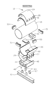
[0011] Figure 1 shows an exploded view of the pipe anchor assembly in
accordance with
a preferred embodiment of the present invention.
[0012] Figure 2 is a head on view of the pipe anchor assembly in
accordance with
another preferred embodiment of the present invention.
[0012.1] Figure 3A shows an exploded view of an alternative pipe anchor
assembly in
accordance with a preferred embodiment of the present invention.
[0012.2] Figure 36 shows an exploded view of an alternative pipe anchor
assembly in
accordance with a preferred embodiment of the present invention.
[0012.2] Figure 3C shows an exploded view of an alternative pipe anchor
assembly in
accordance with a preferred embodiment of the present invention.
2768349
CA 2841949 2018-12-17

CA 02841949 2014-01-14
WO 2013/032583 PCT/US2012/046157
4
Detailed Description of the Preferred Embodiments:
[0013] Detailed descriptions of the preferred embodiments are provided
herein. It is
to be understood, however, that the present invention may be embodied in
various
forms. Various aspects of the invention may be inverted, or changed in
reference to
specific part shape and detail part location, or part composition. Therefore.
specific
details disclosed herein are not to be interpreted as limiting, but rather as
a basis for the
claims and as a representative basis for teaching one skilled in the art to
employ the
present invention in virtually any appropriately detailed system, structure or
manner.
[0014] Turning first to Figure 1, there is shown a pipe anchor in
accordance with the
If) preferred embodiment of the present invention. Pipe anchor 10 is shown
in the
exploded view encircling a cross-sectional length of pipe 15 Pipe anchor 10
captures
pipe 15 in two ways. First, pipe anchor 10 clamps to pipe 15, encircling it
completely
and is secured bolting by assemblies 62, described in more detail below.
Simultaneously, pipe trunnion stop 21 engages with cavity 44 in the base
assembly 42,
IS also described in more detail below.
[0015] Pipe trunnion stop 21 is welded to pipe 15 in the preferred,
illustrated
embodiment, though other ways of securing pipe trunnion stop 21 to pipe 15 may
be
used, including intermediate tabs and bolts, brazing, and integrally
fabricating the stop
on the pipe section. The cross-sectional shape of pipe trunnion stop 21 is
shown as
20 rectangular; but it will be appreciated that the shape may be of a
variety of shapes,
depending upon the particular environment in which the pipe anchor assembly is

intended to be used. The pipe trunnion stop 21 in conjunction with the
opposing cavity
44 in base assembly 62 offers improved anchoring. Preferably, it will be
shaped in a

CA 02841949 2014-01-14
WO 2013/032583 PCT/US2012/046157
polygonal configuration to prevent slippage or movement within the cavity. In
some
embodiments, it may be also be circular, oval or elliptical. The base assembly
42 length
and width along with pipe trunnion stop 21 length and width can be modified as
required
to develop sufficient area to oppose the forces generated by movement from
forces to
the pipe 15.
[0016] Pipe anchor 10 includes top cradle 24 and base cradle 27. Top
cradle 24
includes bolting tubes 25 that mate with bolting tubes 26 on base cradle 27.
By these
mating bolting tubes 25, 26, pipe anchor 10 encircles pipe 15. Bottom cradle
24 also
includes pass-though void 29 so that pipe trunnion stop 21 may pass through
and be
secured in base assembly 42 as illustrated. In the illustrated embodiment,
there are
shown eight bolting tubes 25 on top cradle 24, and eight mating bolting tubes
26 on
base cradle 27, though it will be appreciated that any appropriate number of
bolting
tubes may be employed, depending upon the environment. Alternatively, mating
top
cradle 24 and base cradle 27 may be hingedly attached on one side and
appropriately
.. affixed to each other on the other side with bolts or other mechanisms
known in the art.
[0017] To provide required insulation to the pipe 15 in the area of
pipe anchor 10,
top thermal insulation 31 is provided and located between pipe 15 and top
cradle 24.
Similarly, lower thermal insulation 33 is located between pipe 15 and base
cradle 27.
Also provided in lower thermal insulation 33 is pass-though void 36 to allow
pipe
trunnion stop 21 to pass through lower thermal insulation 33 and mate securely
with
base assembly 42 as illustrated. As can be readily appreciated, the preferred
design
includes a void or space for insertion of insulation about the trunnion and
other areas
where thermal loss may be present. Alternatively, pipe 15 may be secured to
top

CA 02841949 2014-01-14
WO 2013/032583 PCT/US2012/046157
6
thermal insulation 31 and lower thermal insulation 33 by encircling straps,
ties, or other
circumferential brackets which allow for passage of the pipe trunnion stop 21.
Also,
cradles may be configured to encircle pipe 15 and then bracketed or strapped
to
encircle pipe 15 and permit use of insulation.
[0018] Due to pipe trunnion stop 21 being attached to pipe 15, further
insulation
is desired. Accordingly, axial stop structural insulation 51 is shown forward
and aft of
the forward and rearward side walls of pipe trunnion stop 21, to insulate
around pipe
trunnion stop 21 and aide in axial stability of pipe 15. Similarly, lateral
stop structural
insulation 53 is shown adjacent lateral side walls of pipe trunnion stop 21,
to provide
insulation and aide in lateral stability of pipe 15. To complete insulation
around pipe
trunnion stop 21, there is provided vertical stop structural insulation 55,
and aides in
vertical stability of pipe trunnion stop 21. Axial stop insulation 51, lateral
stop structural
insulation 53, and vertical stop structural insulation 55 are shown in Figure
1 as
separated by some distance from pipe trunnion stop 21, but it is only for
illustrative
purposes, and in use, are immediately adjacent the respective walls of pipe
trunnion
stop 21.
[0019] Continuing in Figure 1, there is shown base assembly 42 on
which pipe
15, along with pipe anchor 10, are supported. Base assembly 42 is curved to
support
and provide stability for pipe 15 and base cradle 27. Base assembly 42 further
includes
cavity 44 into which pipe trunnion stop 21 along with axial stop insulation
51, lateral stop
structural insulation 53, and vertical stop structural insulation 55 fit.
Support fins 45 are
also illustrated on base assembly 42 to provide additional structural support,
and it will
be understood that any number and design of support fins may be employed for a

CA 02841949 2014-01-14
WO 2013/032583 PCT/US2012/046157
7
particular purpose. Base assembly 42 fits onto base assembly support 61 as
shown in
Figure 1 and includes external axial stops 65 and external lateral stops 67 to
provide
additional axial and lateral support to deter movement of pipe 15. In the
field, base
assembly support 61 is often pre-existing and base assembly 42 is attached to
base
assembly support 61 by, in the illustrated embodiment, welding.
[0020] As illustrated in the preferred embodiment, pipe trunnion stop
21 provides
improved lateral, axial and vertical support while maintaining insulation for
pipe 15. It
will be appreciated that in the particular insulation used is not part of the
inventions, and
any appropriate insulation material may be used. In the preferred embodiment
shown,
a thin insulation based on aerogel may be employed including insulation sold
under the
trademark Cryogel .
[0021] Turning next to Figure 2, there is shown a front view of a pipe
anchor in
accordance with another preferred embodiment of the present invention. Similar

elements of Figure 1, described above, are labeled with similar number labels
for
consistency, though with a prime after the number label. The embodiment of
Figure 2
shows four pipe trunnion stops 21' positioned around the circumference of the
pipe at
approximately 0 , 90 , 180 , and 270 . It will be appreciated by those in the
art that any
one, two, three or all four pipe trunnion stops 21' may be used and can be
positioned at
any location about the pipe circumference, as is appropriate for the
particular
environment and use desired. To accommodate four pipe trunnion stops 21', bolt
assembly 62' is offset at approximately 45 for the horizontal, though any
appropriate
positioning may be employed. Depending upon the number and location of pipe
trunnion stops 21', the number and location of cradle pass-though voids, as
well as

8
insulation pass-through voids and base assemblies and respective voids 44'
will also be
adjusted. As noted above, encircling metal brackets, straps or straps to affix

circumferential metal casing may be employed without departing from the scope
of the
invention.
[0022] While the invention has been described in connection with a
preferred
embodiment, it is not intended to limit the scope of the invention to the
particular form set
forth, but on the contrary, it is intended to cover such alternatives,
modifications, and
equivalents as may be included within the scope of the invention as defined by
the
appended claims.
[0023] Turning next to Figures 3A, 3B, and 30, there are shown alternative
preferred
embodiments of the present invention, in which the trunnion stops 21", 21¨ and
21¨ are
shown in Figures 3A, 3B, and 30 respectively as having a polygonal cross
sectional
configuration of an ellipse, oval or circle. Trunnion stops 21", 21" and 21"
are
surrounded by insulation in similar fashion to items 51, 53 and 55 as shown in
Figure 1
by respective elements 51", 53", and 55", 51", 53¨, and 55¨, and 51", 53¨, and
55¨. The remaining elements of Figures 3A, 3B, and 30 have similar function to
those
described in Figure 1, but with a double, triple, or quadruple primes after
the item
number to reflect similar items whose only difference is to conform with the
different
trunnion stops 21", 21", and 21".
2768207
CA 2841949 2018-12-17

Representative Drawing
A single figure which represents the drawing illustrating the invention.
Administrative Status

For a clearer understanding of the status of the application/patent presented on this page, the site Disclaimer , as well as the definitions for Patent , Administrative Status , Maintenance Fee  and Payment History  should be consulted.

Administrative Status

Title Date
Forecasted Issue Date 2020-06-02
(86) PCT Filing Date 2012-07-11
(87) PCT Publication Date 2013-03-07
(85) National Entry 2014-01-14
Examination Requested 2017-07-04
(45) Issued 2020-06-02

Abandonment History

There is no abandonment history.

Maintenance Fee

Last Payment of $263.14 was received on 2023-06-23


 Upcoming maintenance fee amounts

Description Date Amount
Next Payment if small entity fee 2024-07-11 $125.00
Next Payment if standard fee 2024-07-11 $347.00

Note : If the full payment has not been received on or before the date indicated, a further fee may be required which may be one of the following

  • the reinstatement fee;
  • the late payment fee; or
  • additional fee to reverse deemed expiry.

Patent fees are adjusted on the 1st of January every year. The amounts above are the current amounts if received by December 31 of the current year.
Please refer to the CIPO Patent Fees web page to see all current fee amounts.

Payment History

Fee Type Anniversary Year Due Date Amount Paid Paid Date
Application Fee $400.00 2014-01-14
Maintenance Fee - Application - New Act 2 2014-07-11 $100.00 2014-06-23
Maintenance Fee - Application - New Act 3 2015-07-13 $100.00 2015-06-22
Maintenance Fee - Application - New Act 4 2016-07-11 $100.00 2016-07-07
Request for Examination $800.00 2017-07-04
Maintenance Fee - Application - New Act 5 2017-07-11 $200.00 2017-07-05
Maintenance Fee - Application - New Act 6 2018-07-11 $200.00 2018-07-09
Maintenance Fee - Application - New Act 7 2019-07-11 $200.00 2019-07-08
Final Fee 2020-04-20 $300.00 2020-03-30
Maintenance Fee - Patent - New Act 8 2020-07-13 $200.00 2020-07-13
Maintenance Fee - Patent - New Act 9 2021-07-12 $204.00 2021-07-21
Late Fee for failure to pay new-style Patent Maintenance Fee 2021-07-21 $150.00 2021-07-21
Maintenance Fee - Patent - New Act 10 2022-07-11 $254.49 2022-07-11
Maintenance Fee - Patent - New Act 11 2023-07-11 $263.14 2023-06-23
Owners on Record

Note: Records showing the ownership history in alphabetical order.

Current Owners on Record
RILCO MANUFACTURING COMPANY, INC.
Past Owners on Record
None
Past Owners that do not appear in the "Owners on Record" listing will appear in other documentation within the application.
Documents

To view selected files, please enter reCAPTCHA code :


To view images, click a link in the Document Description column. To download the documents, select one or more checkboxes in the first column and then click the "Download Selected in PDF format (Zip Archive)" or the "Download Selected as Single PDF" button.

List of published and non-published patent-specific documents on the CPD .

If you have any difficulty accessing content, you can call the Client Service Centre at 1-866-997-1936 or send them an e-mail at CIPO Client Service Centre.


Document
Description 
Date
(yyyy-mm-dd) 
Number of pages   Size of Image (KB) 
Final Fee 2020-03-30 4 97
Representative Drawing 2020-05-05 1 13
Cover Page 2020-05-05 1 47
Maintenance Fee Payment 2020-07-13 1 33
Representative Drawing 2014-02-18 1 18
Abstract 2014-01-14 2 82
Claims 2014-01-14 5 262
Drawings 2014-01-14 2 83
Description 2014-01-14 8 606
Cover Page 2014-02-21 1 52
Request for Examination 2017-07-04 1 43
Examiner Requisition 2018-06-18 5 289
Maintenance Fee Payment 2018-07-09 1 33
Amendment 2018-12-17 33 1,302
Description 2018-12-17 8 527
Claims 2018-12-17 5 158
Drawings 2018-12-17 5 125
Examiner Requisition 2019-03-04 3 179
Maintenance Fee Payment 2019-07-08 1 33
Amendment 2019-09-03 13 433
Claims 2019-09-03 5 159
PCT 2014-01-14 3 204
Assignment 2014-01-14 5 128