Note: Descriptions are shown in the official language in which they were submitted.
CA 02842673 2014-01-21
WO 2013/016134 PCT/US2012/047396
ERGONOMIC BACKPACK
[0001] This application claims priority to U.S. Provisional Patent Application
Serial No.
61/510,976 filed on July 22, 2011 and U.S. Provisional Patent Application
Serial No.
61/638,787, filed on April 26, 2012. The entire contents of both these
application are
incorporated herein by reference.
BACKGROUND
[0002] Backpacks are widely used by students and other wearers/users to store
books,
school supplies, travel supplies, etc. Such backpacks may include a pair of
straps that
extend over a wearer's shoulders when the backpack is worn. However, existing
backpack
configurations can cause discomfort and/or fatigue, particularly when the
backpack is used
to store bulky and/or heavy items.
SUMMARY
[0003] In one embodiment, the present invention is a backpack including a
backpack body
having an inner cavity therein. The backpack body includes a releasable
closure
configured to provide access to the inner cavity and a back surface configured
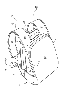
to be
positioned adjacent a back of a wearer when the backpack is worn. The backpack
further
includes a shoulder strap assembly coupled to the backpack body and configured
to be
positioned about a shoulder of the wearer when the backpack is worn. The
shoulder strap
assembly is coupled to an upper portion of the backpack body only at an
attachment
location that is located on an opposite side of the releasable closure
relative to the back
surface.
BRIEF DESCRIPTION OF THE DRAWINGS
[0004] Fig. 1 is a front perspective view of one embodiment of the backpack of
the present
invention;
[0005] Fig. 2A is a front perspective view of another embodiment of the
backpack;
[0006] Fig. 2B is a rear perspective view of the backpack of Fig. 2A;
[0007] Fig. 3 is a right side view of the backpack of Fig. 2A, being worn by a
wearer;
[0008] Fig. 4A is a left side view of the backpack of Fig. 2A;
[0009] Fig. 4B shows the backpack of Fig. 4A, with the straps pivoted to the
front side;
1
CA 02842673 2014-01-21
WO 2013/016134 PCT/US2012/047396
[0 0 1 0] Fig. 5 is a right side view of the backpack of Fig. 2A;
[0011] Fig. 6 is a front view of another embodiment of the backpack;
[0012] Fig. 7 is a back view of the backpack of Fig. 6, with the straps
pivoted to the front
side;
[0013] Fig. 8A is a left side view another embodiment of the backpack;
[0014] Fig. 8B is a front view of the backpack of Fig. 8A;
[0015] Fig. 8C illustrates the backpack of Fig. 8B with the straps pivoted to
the front side;
[0016] Fig. 9 is schematic side view of the backpack of Fig. 1, showing
certain
dimensions;
[0017] Figs. 10A-10D illustrate examples of the backpack of Fig. 9, showing
various
shoulder strap attachment points;
[0018] Fig. 11A is a front view of another embodiment of the backpack;
[0019] Fig. 11B is a front view of another embodiment of the backpack;
[0020] Fig. 12A is a side view of the backpack of Fig. 11A;
[0021] Fig. 12B is a side view of the backpack of Fig. 11B;
[0022] Fig. 13A is a bottom perspective view of the backpack of Fig. 11A;
[0023] Fig. 13B is a bottom perspective view of the backpack of Fig. 11B;
[0024] Fig. 14A is a bottom view of the backpack of Fig. 11A; and
[0025] Fig. 14B is a bottom view of the backpack of Fig. 11B.
DETAILED DESCRIPTION
[0026] The terms "front" and "back," are used herein in relation to a backpack
such that
the region or face that is nearest the back of the wearer, when the backpack
is worn, is
referred to as the "back." The region or face of the backpack that faces away
from the
wearer when the backpack is worn, and that usually faces toward a customer
during display
of the backpack for sale in a store, and which may carry a logo, is referred
to as the "front."
The back may be flatter, more planar, and more uniform in appearance than the
front, and
the front may have or carry zippers, fasteners, openings/slits or other
devices for providing
access to a main cavity of the backpack.
[0027] With reference to Fig. 1, the backpack 10 of the present invention may
include a
body 12 with an inner cavity, or major storage compartment 14, therein. The
body 12
includes a back surface or panel 16 configured to lie adjacent to the back of
a wearer and a
generally parallel front surface or panel 50 opposing the back panel 16 and
facing away
2
CA 02842673 2014-01-21
WO 2013/016134 PCT/US2012/047396
from the wearer when the backpack 10 is worn. The backpack 10 may also include
a pair
of opposed sides 18 positioned generally perpendicular to, and extending
between the back
16 and front 50 panel. The backpack 10 may further include a top surface or
panel 19 and
a bottom surface or panel 17 extending between and generally perpendicular to,
the back
16 and front 50 panels, and the sides 18.
[0028] In the illustrated embodiment the backpack 10 is generally shaped as a
rectangular
prism with six generally well defined sides/surfaces. However, it should be
understood
that the backpack 10 may not necessarily have well defined surfaces or panels,
and could
instead have a more undefined, unstructured shape. In this case, however, the
backpack
can still be considered to have at least a back surface 16, positioned
adjacent a wearer's
back when the backpack 10 is worn, and a generally opposed front surface 50
not
positioned adjacent a wearer's back.
[0029] The backpack 10 may include a shoulder strap assembly 25 including pair
of
shoulder straps 20 coupled to the body 12. Each shoulder strap 20 can extend
from a top
portion of the body 12/front panel 50 (e.g., in one case, the upper half of
the body 12) to a
position at or adjacent to the bottom of the body 12/back panel 16 (e.g. in
one case the
lower half of the body 12). In this manner each shoulder strap 20 forms a loop
which can
receive the wearer's arms therethrough. Alternately, if desired, rather than
using two
shoulder straps 20, the shoulder strap assembly 25 may include only a single
shoulder strap
20 to provide a backpack 10 also known as a "sling."
[0030] The lower end 20' of each shoulder strap 20 may be made of a different
material or
may have a different shape (for instance, a narrower strap, or an unpadded
strap) than the
rest of shoulder strap 20, although if desired the shoulder strap 20 can have
a relatively
uniform size, shape and material along its length. Each shoulder strap 20 may
include an
adjustment mechanism, such as a buckle 23 or the like, such that the length of
each strap 20
can be customized to fit different sized wearers, and accommodate different
load weights.
[0031] The backpack 10 may include a releasable fastener/closure or a closable
access
opening 24 extending around the body 12 such that when the releasable closure
24 is
opened, access is thereby provided to the major storage compartment 14. The
releasable
closure 24 can, in one embodiment, extend generally vertically (when the
backpack 10 is
worn) from one side panel 18, horizontally across the top panel 19, and
vertically across
the other side panel 18, to provide ease of use and full access to the storage
compartment
14. The releasable closure 24 can take any of a variety of forms, including a
zipper, a slide
3
CA 02842673 2014-01-21
WO 2013/016134 PCT/US2012/047396
fastener, hook-and-loop fastening material (i.e. VELCRO ), snaps, magnets or
the like.
Although the backpack 10 may include a variety of storage compartments and
releasable
closures, in one case the inner cavity 14 has the greatest storage capacity of
any
pocket/compartment in the backpack 10 by volume, and/or the releasable closure
24 has the
greatest length of any releasable closure of the backpack 10. The backpack 10
may include
one or more outer pockets, such as a mesh pocket 70 (Fig. 2B) positioned on
the outside of
the backpack 10.
[0032] The backpack 10 may include a carrying handle 22 (see Fig. 4A)
positioned on the
top of the body 12/back panel 16 between the shoulder straps 20 to provide a
means by
which the backpack 10 can be manually carried. The body 12, shoulder straps 20
and
handle 22 can be made of a wide variety of materials, including flexible,
durable sheet-like
material, such as polymers (i.e. polyester, nylon), fabric, combinations of
these materials,
etc., in woven or various other forms. Each shoulder strap 20 can include
cushioning or
padding material (such as foam) thereon, and be of an adjustable length, to
allow the
backpack 10 to be carried on the back of the wearer in a well-known manner. In
particular,
the backpack 10 may be configured such that when it is worn by a wearer, the
shoulder
straps 20 are positioned over the shoulder of a wearer, the back panel 16 is
positioned
generally flat against and parallel with the back of a wearer, and the sides
18 are positioned
generally adjacent the sides of a wearer.
[0033] In the embodiment illustrated in Fig. 1 each shoulder strap 20 is
connected to the
front panel 16 on outward side of the releasable closure 24 (i.e. on an
opposite side of the
releasable closure 24 relative to the back panel 16). Each shoulder strap 20
may be secured
to the body 12 at a position on the outer half, or outer 50%, of the
width/thickness of the
backpack 10, or on the outer 25% of the width/thickness (wherein the
width/thickness
direction is perpendicular to the back panel 16, and may be represented, for
example, by
dimension XO in Fig. 9). This configuration for the shoulder straps 20 may
differ from
conventional backpacks where the shoulder straps are connected to the back
panel 16.
[0034] The straps 20 may be configured such that they are the only shoulder
straps 20 of
the backpack 10, and the backpack 10 lacks any other shoulder straps
configured to fit
around the shoulders of a wearer. The backpack 10 may lack any straps and/or
shoulder
straps directly coupled to the back panel 16, and lack any straps and/or
shoulder straps
coupled to the backpack 10 at any position in the inner half of the thickness
of the body 12,
particularly in the upper half thereof. In addition, the shoulder straps 20
may be configured
4
CA 02842673 2014-01-21
WO 2013/016134 PCT/US2012/047396
to bear the entirely of the weight of the backpack 10 when the backpack 10 is
worn (except
possibly for frictional forces between a wearer's back and the back panel 16)
or being
donned or doffed, and configured that the entire shoulder strap 20 load is
applied to the
front panel 50 or front portions of the backpack 10, and none of the shoulder
strap 20 load
is directly applied to the back panel 16 or back portions of the backpack 10.
In one case
each shoulder strap 20 is coupled to the upper portion of the body 12 at no
more one
attachment location.
[0035] The positioning of the upper portion of the strap 20 as disclosed
herein helps to
ensure that pulling/tension loads, during wearing of the backpack 10, are
largely or entirely
applied to the front surface/front panel 50 of the backpack 10. This
arrangement pulls the
full weight of the backpack 10 up against the wearer's back, moving the weight
closer to
the wearer's center of gravity where it is more easily borne and less likely
to cause
imbalance. In addition, this arrangement distributes the load more evenly
across the
wearer's back. In particular, the shoulder strap arrangement disclosed herein
enables the
backpack's load to be automatically pressed or constrained more evenly against
the entirety
of the wearer's back. In contrast, if the upper portions of the straps 20 were
to be attached
to the back panel 16, or in the back portion of the backpack, such backpacks
tend to adopt a
curved or "C" like shape in side view, moving away from the middle of the
wearer's back
and causing most of the weight to be carried on the hips or lower back of the
wearer.
Moreover, in many cases in such conventional backpacks the load becomes
cantilevered
away from the wearer's back causing additional stress and discomfort to the
wearer.
[0036] Each strap 20 can be made of a relatively flexible/pliable material,
and coupled to
the body 12 at only a single location, such that the straps 20 are pivotally
attached at the
upper attachment locations 20A and can be freely pivoted about the side panels
18 and
generally be positioned on the front side of the backpack 10, as can be seen
in Figs. 4B, 7
and 8c. When in this configuration the straps 20 do not cross over or prevent
access to the
releasable fasteners 24, or at least the upper-most portions of the releasable
fastener 24 or
those portions of the releasable fastener 24 on the top surface 19, thereby
providing full and
free access to the inner cavity 14. The backpack 10 may lack any clips,
brackets, support
members etc. through which the straps 20 pass that may restrain the straps 20
and prevent
them from pivoting to the front of the backpack 10, including any clips,
brackets, support
members etc. that directly or indirectly couple the straps 20 to the upper
half of the body
12.
CA 02842673 2014-01-21
WO 2013/016134 PCT/US2012/047396
[0037] As shown in the embodiment of Fig. 2A, in one case the forward/upper
ends of the
shoulder straps 20 are coupled together by a yoke 21, which is in turn coupled
to the front
panel 50/body 12. Yoke 21 is optional, and if used may be considered an
extension of the
strap or straps 20 and/or part of the shoulder strap assembly 25. When the
yoke 21 is used,
the straps 20 can still be considered to be attached to the front panel 50.
[0038] As illustrated in Fig. 5, the releasable closure 24 may have an S-shape
in side view.
The releasable closure 24 as shown has an end location 26 near the bottom of
the body 12
(i.e. in the lower half of the body 12) and adjacent to the back panel 16
(i.e. within about 0-
3 inches, or within about 50%, or about 25% of the width of the body 12 at
that position).
From the end location 26, the releasable closure 24 may have a first portion
24a that
extends generally upwardly and outwardly (i.e. upwardly away from the back
panel 16) to
the outward-most position 28. The outward-most position 28 of the releasable
closure 24
may be located in the outer half of the body 12 (i.e. in the half of the body
12 furthest away
from the back panel 16) and/or at least about 3 inches, or at least about 4
inches, away from
the back panel 16.
[0039] From the position 28, the releasable closure 24 has a second portion
24b that
extends generally upwardly and inwardly towards the back panel 16 to an
intermediate
position 30 generally adjacent to the back panel 16 and/or one of the shoulder
straps 20.
The releasable closure 24 has a third portion 24c that extends upwardly and
over the top of
the body 12 at a distance generally uniformly spaced from the back panel 16 to
the opposite
side 18 of the body 12. The releasable closure 24 then may continue on the
opposite side
18 in the same pattern, or in a symmetrical or mirror image pattern, to that
shown in Fig. 1.
[0040] In this manner, the releasable closure 24 has a generally "S"-shape (or
"reverse S"
shape) in end view on both sides 18 of the body 12. Alternately, one or both
sides of the
releasable closure 24 may have a different shape than that shown in Fig. 5,
such as a linear
shape and accordingly, may have ends positioned in different locations along
the sides 18
of the backpack 10.
[0041] The serpentine shape of the releasable closure 24 allows for easy side
access to the
major storage compartment 14. In particular, when the releasable closure 24 is
unfastened
from the end location 26 to the intermediate position 30, a generally
triangular side flap 32
is defined in the body 12. The side flap 32 can be pulled away from the rest
of the body 12
to provide a side access opening. In this manner, access is provided to the
major storage
compartment 14 by only partially releasing/opening the releasable closure 24.
Moreover,
6
CA 02842673 2014-01-21
WO 2013/016134 PCT/US2012/047396
the "S"-shape of the releasable closure 24 provides the side flap 32 which can
be
pivoted/folded away from the body 12 to define an opening. This can be
contrasted with a
simple "slit" opening provided by a linear releasable closure which does not
provide the
side flap or associated access and visibility.
[0042] When full access is desired to the major storage compartment 14, the
releasable
closure 24 can be completely opened, thereby allowing access to the major
storage 14
compartment via the top of the body 12/backpack 10. Thus, the releasable
closure 24
provides the option of side access to the major storage compartment 14 on
either side 18 of
the body 12/backpack 10, and also provides the option of full/top-access to
the major
storage compartment 14.
[0043] The releasable closure 24 in the embodiment of Fig. 5 has first portion
24a and
second portion 24b that form an angle therebetween of about 80 degrees, or
less than about
100 degrees. Similarly, various portions of the releasable closure 24, or
tangents thereof, in
the embodiment of Fig. 5 may form an angle of less than about 100 degrees to
form a
relatively well-defined side flap 32. Each side flap 32 may be foldable or
pivotable about a
root or base that is defined by end points of the releasable closure 24/58, or
by sufficient
changes in direction of the releasable closure 24/58.
[0044] The releasable closure 24 on the side panel 18 may form a
substantially, but not
entirely, closed loop to prevent the side flap 32 from being completely
separated from the
backpack 10. Although only a single side flap 32 is visible in Fig. 5, it
should be
understood that both side panels 18 may include a side flap 32 so that side
access to the
major storage compartment 14 can be provided regardless of the orientation of
the body
12/backpack 10. If desired, a top access releasable closure (for example,
closure 38 in Fig.
6) may be provided in the front panel 50 or the yoke 21 of the backpack 10 as
shown to
provide top/front access to the major storage compartment 14.
[0045] As shown in Fig. 6, various additional releasable fasteners/closures
36, 37, 38 may
extend across the front face of the body 12/backpack 10. In one embodiment,
each
releasable closure 36, 37, 38 may provide access to the major storage
compartment 14.
Alternately, the releasable closures 36, 37, 38 may provide access to
auxiliary storage
compartments that are positioned adjacent to the major storage compartment 14
which may
be smaller than the major storage compartment 14.
[0046] Figs. 8A and 8B illustrate an alternate embodiment in which the
backpack 10'
includes a front panel 50, back panel 16, opposed side panels 18, and bottom
panel 56.
7
CA 02842673 2014-01-21
WO 2013/016134 PCT/US2012/047396
Compression straps 68 having a variable length may be provided on one or both
sides of
the backpack 10' to help adjust the size of the backpack 10' depending upon
the size/bulk of
its contents.
[0047] Fig. 9 is a side schematic view of a backpack 10, indicating certain
dimensions.
The top panel 19 has a depth XO, the front panel 50 has a height YO, and the
back panel 16
has a height ZO. The shoulder straps 20 are attached to the body 12 at an
upper attachment
point 20A which, in the embodiment of Fig. 9, is at the junction of the top
panel 19 and
front panel 50. The shoulder straps 20 may also have a lower attachment point
20B which,
in the illustrated embodiment, is at the junction of the back panel 16 and
bottom panel 17.
[0048] The upper 20A and lower 20B attachment points can be varied as desired.
For
example, Figs. 10A-10D illustrate various alternate locations for the shoulder
strap
attachment points 20A, 20B, although other locations are also possible besides
those shown
herein. As shown in Fig. 10A, the upper attachment points 20A may be located
on the
upper part of the front panel 50. In one particular embodiment the upper
attachment points
20A may be located a distance Y1 from the top of the front panel 50 (or the
highest
position of the body 12), where the ratio of Yl/Y0 may be less than about 0.5,
or less than
about 0.25, or less than about 0.10, such that the weight transfer
characteristics outlined
above are still maintained. In one embodiment the upper attachment points 20A
are not
positioned on the back panel 16.
[0049] Instead of being located exactly at the junction of the back panel 16
and bottom
panel 17 as shown in Fig. 9, in Fig. 10A the lower attachment points 20B are
located on the
lower part of the back panel 16, about a distance Z1 from the bottom of the
back panel 16
(or from the lower position of the body 12). In one case the ratio Z1/Z0 may
be less than
about 0.5, or less than about 0.25, or less than about 0.1.
[0050] As shown in Fig. 10B, the upper attachment points 20A may be located on
the front
part of the top panel 19, located a distance X1 from the front panel 50 or
forward-most
position of the body 12, where the ratio of Xl/X0 may be less than about 0.5,
or less than
about 0.25, or less than about 0.1. The lower attachment points 20B may be
located on the
lower part of the back panel 16, about a distance Z1 from the bottom of the
back panel
16/lower-most portion of the body 12, where the ratio Z1/Z0 may be between
about 0.25
and about 0.50.
[0051] As shown in Fig. 10C, instead of being attached to the back panel 16,
the lower
attachment points 20B may be positioned on the side panel 18, with the same
height ranges
8
CA 02842673 2014-01-21
WO 2013/016134 PCT/US2012/047396
as outlined above when the attachment points 20B are on the back panel 16.
Similarly, as
shown in Fig. 10D, the upper attachment points 20A may be positioned on the
side panel
18, with the same height ranges as outlined above. In the case shown in Fig.
10D the upper
attachment points 20A are spaced a distance X1 away from the front panel
50/front of the
body 12, and spaced a distance Y1 away from the top panel 19/top of the body
12. The
ratio of Xl/X0 and/or Y1/Y0 can fall within the ranges outlined above. The
various
locations of the upper 20A and lower 20B attachment points may be used in
various
combination with one another, including using differing upper 20A and/or lower
20B
attachment points for the differing straps 20 on the same backpack 10.
[0052] In one embodiment the lower attachment points 20B are positioned in the
rear half
of the width of the XO of the backpack 10, and entirely spaced away from the
front panel
50. This connection location helps to provide symmetry and stability to the
backpack 10,
particularly when the upper attachment point 20A is positioned in the front
half of the
width of the backpack 10. In addition, in one embodiment each shoulder strap
20 is
attached to the backpack 10, at the bottom half thereof, at only a single
attachment point
20B, and the backpack 10 lacks any other straps or strap portions that extend
between the
shoulder strap 20 and the bottom half of body 12 of the backpack. In addition
in one
embodiment the backpack 10 lacks any straps that are coupled to lower half of
the front
panel 50 and/or that extend along or over the bottom panel(s) 17.
[0053] As outlined above, the shoulder strap attachment points 20A, 20B having
the
configuration/arrangement outlined above can be configured to pull the
backpack load
closer to the wearer's back, automatically compensating for different sized
wearers and/or
load weights. Each shoulder strap 20 may include an adjustment mechanism, such
as a
buckle 23 or the like, so that the length of each strap 20 can be customized
to fit different
sized wearers, and accommodate different load weights. The use of an
adjustable length
strap 20 can help to ensure that the weight-distribution benefits outlined
above are fully
realized, as an ill-fitting backpack 10 may not be able to fully provide such
benefits to all
wearers.
[0054] Figs. 11-14 illustrate additional backpacks which may include the
ergonomic
shoulder strap construction, in which the bottom structures may differ from
the examples
provided above. In particular, Fig. 11A is a front view of a backpack 10
utilizing a single
bottom panel 17 that is somewhat rounded/curved. Fig. 11B is a front view of a
backpack
utilizing a two-part bottom made of panels 17A and 17B. In this embodiment the
bottom
9
CA 02842673 2014-01-21
WO 2013/016134 PCT/US2012/047396
panel 17A is somewhat flattened. Although Fig. 11B illustrates a bottom made
of two
panels, more than two panels could be used for the bottom. The number, size,
and shape of
the bottom panels may be chosen according to manufacturing preference. In some
instances the use of multiple bottom panels may simplify construction, reduce
costs, or
provide other benefits. However in other cases the use of fewer or one panel
may be
preferred. The bottom panel 17 and/or panels 17A/17B may have the same or less
stiffness/rigidity as the side panels 18, back panel 16, front panel 50 and/or
top panel 19 to
lend flexibility and comfort to the backpack 10.
[0055] Fig. 12A is a right side view of the backpack 10 of Fig. 11A, and Fig.
12B is a right
side view of the backpack 10 of Fig. 11B. As can be seen, the backpack in Fig.
12A has a
somewhat rounded bottom (as denoted at B1) while the backpack in Fig 12B has a
somewhat flattened bottom (as denoted at B2). Fig. 13A is a lower perspective
view of the
backpack 10 of Fig. 11A, and Fig. 13B is a lower perspective view of the
backpack of Fig.
11B, and these figures further illustrate the bottom details including a
single bottom panel
17 and two bottom panels 17A, 17B, respectively. Finally, Fig. 14A is a bottom
view of
the backpack 10 of Fig. 11A, and Fig. 14B is a bottom view of the backpack of
Fig. 11B.
[0056] Having described the invention in detail and by reference to the
various
embodiments, it will be apparent that modifications and variations thereof are
possible
without departing from the scope of the invention.
[0057] What is claimed is: