Note: Descriptions are shown in the official language in which they were submitted.
CA 02843331 2014-02-20
METHOD AND SYSTEM FOR
MONITORING DOWNHOLE ASSETS
TECHNICAL FIELD
This disclosure relates to monitoring of assets used in downhole operations.
BACKGROUND ART
U.S. Patent Publication No. 2012/0075113 (Loi et al.) discloses a method and
apparatus
for automatic downhole asset monitoring. In Loi et al., downhole assets of
interest are tagged
with surface acoustic wave (SAW) or radio frequency identification (RFID)
transponders. A rig
reader comprising antennas and interrogators provides the ability to read
tagged information
from the tagged assets. The rig reader is positioned below a rig floor or
rotary table, and the tags
are read as the assets pass through the rig reader. A controller controls the
rig reader to turn on or
turn off in order to start or stop a reading process. The reader may include a
motion detection
device for sensing drill string motion in order to restrict reading of tags to
when the drill string is
moving. The controller is connected to a computer and may send collected and
processed data
received from the rig reader to the computer.
SUMMARY OF INVENTION
This disclosure describes monitoring of downhole assets throughout the
lifetime of the
downhole assets. As will be further explained, the results of the monitoring
can be used for
various purposes, such as determining when to retire a downhole asset,
determining when to
order new parts to build another downhole asset, determining how much to
charge a customer for
usage of a downhole asset, and so forth. The invention described in this
disclosure provides an
integrated approach to monitoring of downhole assets that takes into account
both what happens
to a downhole asset while the downhole asset is in a use environment and what
happens to the
downhole asset while the downhole asset is not in a use environment.
In one illustrative embodiment of the invention, a method for monitoring
downhole assets
comprises tracking a location of a downhole asset relative to a first
environment. The method
further includes acquiring configuration information of the downhole asset,
wherein the
- 1 -
CA 02843331 2014-02-20
configuration information comprises a measurement of one or more forces
applied to the
downhole asset during assembly of the downhole asset in the first environment.
The method
includes determining a service life of the downhole asset from the
configuration information.
The method includes measuring one or more parameters related to usage of the
downhole asset
in a second environment. The method further includes determining a remainder
of the service life
of the downhole asset by reducing the service life by an amount proportional
to usage of the
downhole asset as indicated by the measurement related to usage of the
downhole asset.
In another illustrative embodiment of the invention, a system for monitoring
downhole
assets comprises at least one processor and a memory coupled to the at least
one processor,
wherein the memory stores program instructions executable by the at least one
processor to:
(i) receive location information of a downhole asset relative to a first
environment;
(ii) receive configuration of the downhole asset, where the configuration
information
comprises a measurement of one or more forces applied to the downhole asset
during assembly of the downhole asset in the first environment;
(iii)
determine a service life of the downhole asset using the configuration
information;
(iv) receive usage information of the downhole asset, where the usage
information
comprises usage time and one or more other usage parameters of the downhole
asset in a second environment; and
(v)
determine a remainder of the service life of the downhole asset by reducing
the
service life by an amount proportional to the usage of the downhole asset as
indicated by the measurement related to usage of the downhole asset.
In yet another illustrative embodiment of the invention, a system for
monitoring
downhole assets comprises at least one electronic tag associable with a
downhole asset, with the
at least one electronic tag containing a unique asset identification code. The
system further
includes at least one reader for interrogating the at least one electronic tag
for an asset
identification code. The system also includes at least one downhole monitoring
package
associable with the downhole asset, with the at least one downhole monitoring
package being
configured to measure and record one or more parameters related to usage of
the downhole asset.
- 2 -
CA 02843331 2014-02-20
The system further includes at least one processor and memory coupled to the
at least one
processor, wherein the memory stores program instructions executable by the at
least one
processor to determine a service life of the downhole asset from configuration
information and
usage information of the downhole asset, wherein the configuration information
comprises a
measurement of one or more forces applied to the downhole asset during
assembly of the
downhole asset.
The illustrative embodiments described above are intended to provide an
introduction to
the invention. They are not intended to identify key or critical elements of
the invention or to
delineate the scope of the invention. Various embodiments of the invention
will be described in
greater detail below with reference to the accompanying drawings.
BRIEF DESCRIPTION OF DRAWINGS
The following is a description of the Figures in the accompanying drawings.
The Figures
are not necessarily to scale, and certain features and certain views of the
Figures may be shown
exaggerated in scale or in schematic in the interest of clarity and
conciseness.
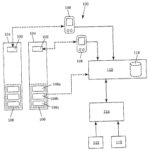
FIG. 1 is a block diagram of a system for monitoring downhole assets.
FIG. 2 is a block diagram of a computer system in which the system for
monitoring
downhole assets could be implemented.
FIG. 3 is a block diagram of a service facility.
DESCRIPTION OF EMBODIMENTS
In the following description, numerous specific details may be set forth in
order to
provide a thorough understanding of various embodiments of the invention.
However, it will be
clear to one skilled in the art when the invention may be practised without
some or all of these
specific details. In other instances, well-known features or processes may not
be described in
detail. In addition, like or identical reference numerals may be used to
identify common or
similar elements.
- 3 -
CA 02843331 2014-02-20
As used herein, the term "downhole asset" refers to an asset that may be used
in a
downhole operation, and in particular to an asset that may be included in a
drill string or other
tool string configured to perform a downhole operation. Examples of such
assets include, but are
not limited to, drill motors, jars, agitators, pipes, and the like. As used
herein, a "downhole
operation" is an operation carried out in a well or borehole, such as drilling
and the like. Each
downhole asset has a "service life," i.e., the total number of hours the
downhole asset can be
used in a downhole operation before the downhole asset starts providing
substandard
performance. At any instance, the remaining service life of the downhole asset
may be estimated
roughly as the service life reduced by the usage time of the downhole asset.
While the downhole asset is being used in a downhole operation, the downhole
asset may
be exposed to distressing factors; i.e., factors that can potentially or
effectively reduce the service
life of the downhole asset. To obtain a more accurate estimate of the
remaining service life of the
downhole asset, an equivalent usage time of the downhole asset that takes into
account the
distressing factors may be determined. The remaining service life would then
be the service life
reduced by the equivalent usage time. There may also be distressing factors
during assembly of
the downhole asset that can potentially or effectively reduce the service life
of the downhole
asset. To obtain an even more accurate estimate of the remaining service life,
the distressing
factors during assembly of the downhole asset may be factored into an estimate
of the service life
of the downhole asset.
FIG. 1 shows one illustrative embodiment of a system 100 for monitoring
downhole
assets. The system 100 includes electronic tags 102 embedded in or attached to
downhole assets
104. Each electronic tag 102 contains a unique asset identification code. The
electronic tags 102
may be radio frequency identification (RFID) tags or other type of radio tags,
e.g., long
wavelength identification (LWID) tags. A commercial example of a LWID tag is a
RuBee radio
tag using IEEE 1902.1 standard. RuBee radio tags operate at low frequencies
that are not
attenuated by water and metal, e.g., below 450 kHz and optimally at 131 kHz,
which allows
RuBee radio tags to be read more accurately in environments containing a high
amount of liquid
and metal compared to traditional RFID tags. Each downhole asset 104 may have
one or more
electronic tags 102. For example, a downhole asset 104 may have more than one
electronic tag
102 if the downhole asset 104 is built from multiple subunits and each of the
subunits has its own
- 4 -
CA 02843331 2014-02-20
electronic tag. In general, each downhole asset 104 may be uniquely identified
by a single
electronic tag 102 or a group of electronic tags 102. The electronic tags 102
make it possible to
track the location of the downhole assets 104 in a service facility and to
accurately document the
history of the downhole assets.
The system 100 may include a downhole monitoring package (DMP) 106 placed
within,
or otherwise associated with, each downhole asset 104 for recording usage time
and measuring
one or more other usage parameters while the downhole asset 104 is in a use
environment.
Typically, the other usage parameters measured will be distressing factors.
What is considered as
distressing will generally depend on the nature of the downhole asset 104.
Each DMP 106 may
include a battery module 106a, an electronics module 106b, and sensors 106c.
The electronics
module 106b may include a clock, memory, and processor and may be configured
to receive and
process signals from the sensors 106c. The sensors 106c may be selected based
on the distressing
factors to be monitored. For example, if it is determined that the service
life of the downhole
asset 104 may be sensitive to vibration of the downhole asset and the
temperature to which the
downhole asset is exposed, the distressing factors monitored may include the
vibration of the
downhole asset and the temperature in the use environment of the downhole
asset. Examples of
other distressing factors are shock, strain, torque, weight, and the like. The
sensors 106c may
also measure parameters that may not necessarily be distressing to the
downhole asset 104.
While the downhole asset 104 is in the use environment, the DMP 106 records
usage time
and monitors one or more distressing factors, or other usage parameters. The
DMP 106 may
compute equivalent usage time using the measured data and usage time. In one
or more
embodiments, the equivalent usage time may be computed as the usage time
adjusted by a
multiplier that is determined based on the portion of the measured data
attributable to distressing
factors of interest. For example, to account for the effects of temperature on
the remaining
service life of the downhole asset, a lookup table may be prepared that
associates a certain
multiplier with each predefined temperature range. For example, a low
temperature range
(e.g., < 140 F) may have a multiplier of 1, a medium temperature range (e.g.,
from 141 F to
220 F) may have a multiplier of 1.2, and a high temperature range (e.g., from
221 F to 250 F)
may have a multiplier of 1.4. If accounting for effects of vibration on the
remaining service life
of the downhole asset, the lookup table may also include multipliers for
vibration ranges.
- 5 -
CA 02843331 2014-02-20
If accounting for effects of temperature on remaining service life, the DMP
106 will
collect temperature data using the appropriate sensor(s) 106c. For each
segment of usage time,
the DMP 106 can determine the temperature range from the measured temperature
data. The
DMP 106 can select the appropriate multiplier for the temperature range from
the lookup table
and compute the equivalent usage time for that segment of usage time. For each
additional
segment of usage time, the DMP 106 can compute the additional equivalent usage
time. The
equivalent usage times can be summed up to obtain a running (or total)
equivalent usage time
over a running (or total) usage time. If accounting for effects of vibration
on remaining service
life, the DMP 106 will collect vibration data using the appropriate sensor(s)
106c, and the
appropriate vibration multiplier can be used to adjust the usage time to
obtain the equivalent
usage time in the same manner described above for temperature. A compound
multiplier made of
a temperature multiplier and vibration multiplier may be used if accounting
for the effects of
both vibration and temperature.
The system 100 may include an asset tracking module (ATM) 112 that records the
location of each downhole asset 104 relative to the service facility during
the lifetime of the
downhole asset. In one or more embodiments, the ATM 112 can be used to find
any downhole
asset and view the configuration of the downhole asset during the lifetime of
the downhole asset.
The ATM 112 communicates with readers 108 that are configured to interrogate
or scan the
electronic tags 102 on the downhole assets 104. Each reader 108 includes the
necessary circuitry
or logic to communicate with the electronic tags 102 and antennas to
communicate signals to and
from the electronic tags 102. As part of interrogating an electronic tag 102,
a reader 108 may
generate electromagnetic signals with sufficient power to energize the
electronic tag 102 and
cause the electronic tag 102 to return a uniquely coded signal. In other
cases, the electronic tags
102 may have batteries or receive power from some other source and may not
need to be
energized by the readers 108.
The readers 108 may be portable devices in some embodiments. In other
embodiments,
the readers 108 may be fixed at particular locations within a service
facility, effectively turning
those locations into scanning zones. In some embodiments, the reader data that
the reader 108
sends to the ATM 112 may include positioning information such that the ATM 112
is able to
determine the location of the downhole asset referenced in the reader data
automatically.
- 6 -
CA 02843331 2016-01-22
Alternatively, after a downhole asset is scanned into the ATM 112 by receiving
appropriate data
from a reader 108, the location of the downhole asset may be manually supplied
to the ATM 112
and recorded against the downhole asset.
The system 100 may include a service logging module (SLM) 114 for recording
and
displaying information about services performed on each downhole asset 104 at
any time during
the lifetime of the downhole asset. In one or more embodiments, the SLM 114
may allow service
reports to be generated from the recorded data. In one or more embodiments,
the SLM 114
communicates with measuring devices 115 and collects data from the measuring
devices 115. In
some embodiments, the measuring devices 115 may include devices for measuring
distressing
factors on the downhole asset that may affect the service life of the downhole
asset. The
measuring devices 115 may further include diagnostic devices, e.g., devices
that may measure
conditions such as wear of the downhole asset. In one embodiment, one of the
measuring devices
115 is a force-measuring device for measuring one or more forces applied to
the downhole assets
during assembly of the downhole assets. In a particular embodiment, the force-
measuring device
is a torque-measuring device that measures torque applied to the downhole
asset 104 while
making up connections between subunits of the downhole asset 104. The torque-
measuring
device may be a commercial device, such as a LOG MASTERTm torque logger from
National
Oilwell Varco.
When building a downhole asset, the SLM 114 may use the ATM 112 to scan the
subunits to be included in the downhole asset. The SLM 114 may further allow
an electronic
representation of the downhole asset to be constructed using the scanned tag
information from
the ATM 112. The representation may show the subunits in the downhole asset
104 as well as
the connections between the subunits. As the subunits are made up, the SLM 114
receives torque
data from the torque-measuring device and associates the torque data with the
appropriate
connection in the representation of the downhole asset. The service life of
the downhole asset
may be determined from the configuration of the downhole asset, which in one
or more
embodiments takes into account the torque or other type of force applied to
the downhole asset
while assembling the downhole asset. A complete configuration profile of the
downhole asset
may then include the subunits in the downhole asset, identified by their
electronic tags, the
- 7 -
CA 02843331 2014-02-20
connections made in the downhole asset, the torque applied to make up the
connections, and the
resulting service life.
In one or more embodiments, the ATM 112 includes, or communicates with, a
master
database 118 configured to store records of the downhole assets 104. For each
downhole asset
104, the ATM 112 may store information related to configuration of the
downhole asset,
information related to services performed on the downhole asset, information
related to location
of the downhole asset, and information related to usage of the downhole asset.
The ATM 112
may receive service and configuration data from the SLM 114. The ATM 112 may
further
receive data from the DMPs 106 within the downhole assets 104. The data stored
in the master
database 118 may be used for various purposes, such as evaluating performance
of downhole
assets, generating financial reports, billing customers, visualizing the
condition of downhole
assets, and managing inventory.
In one or more embodiments, the ATM 112 determines the remaining service life
of a
downhole asset 104 using monitoring data from the DMP 106 associated with the
downhole asset
104 and service life of the downhole asset 104 as specified in the
configuration of the downhole
asset 104 (or computed from the configuration of the downhole asset 104). The
remaining
service life may generally be determined as the service life reduced by an
amount proportional to
the usage of the downhole asset as indicated by the measurement made by the
DMP 106. More
specifically, the remaining service life may be computed as the service life
less the equivalent
usage time of the downhole asset 104. The equivalent usage time may be
provided with the
monitoring data from the DMP 106. If the DMP 106 does not provide the
equivalent usage time,
the ATM 112 may determine the equivalent usage time using the monitoring data
from the DMP
106. The remaining service life may be further adjusted if the downhole asset
is subject to a
repair service that involves disassembling and subsequently reassembling the
downhole asset;
i.e., the remaining service life may take into account forces applied to the
downhole asset during
the disassembly and reassembly.
In one or more embodiments, the ATM 112 maintains or has access to an
inventory of
parts that can be used to build the downhole assets. As the remaining service
life of the downhole
asset approaches zero, the ATM 112 can automatically initiate ordering of new
parts so that
fulfillment time for a new order for a downhole asset having the same
configuration can be
- 8 -
CA 02843331 2014-02-20
minimized. In one example, the remaining service life may be considered to
approach zero if it is
less than 25% of the original service life. In another example, the remaining
service life may be
considered to approach zero if it is less than 10% of the original service
life. In general, what is
considered as approaching zero may be based on the length of time it would
take to receive the
new order of parts.
In some embodiments, the modules of the system 100 are program instructions
executable by at least one processor. FIG. 2 shows an exemplary computer
system 200 in which
the modules may be implemented. The computer system 200 may include a
processor (or
multiple processors) 202, a memory 204, a display 206, a communications
interface (or
device(s)) 208, and an input interface (or device(s)) 210. For example, the
program instructions
of the ATM 112 and SLM 114 (and the database associated with the ATM 112) may
be stored in
the memory 204 or other data storage media 212 accessible to the computer
system 200 for
subsequent loading into the memory 204. Any of the ATM 112 and SLM 114 may
receive data
from external devices, such as the readers 108, DMPs 106, and measuring
devices 115, through
the communications interface 208, which may use wired and/or wireless
communications
protocols. Any of the ATM 112 and SLM 114 may receive user input through the
input interface
210 and may present information on the display 206.
In some embodiments, the computer system 200 may be configured as a server
computer,
and one or more client computers, which may be located in various areas of a
service facility or
outside of the service facility, may communicate with the computer system 200
over a suitable
network. In this case, the ATM 112 and SLM 114 may be accessible through any
of the client
computers. The ATM 112 and SLM 114 may be accessible through dedicated
applications or
web browsers on the client computers. Interaction with the ATM 112 and SLM 114
through any
client computer may involve storing data locally on the client computer. The
local data can be
subsequently transmitted to the server computer, e.g., to allow
synchronization of data across all
the modules. It is also possible that the ATM 112 is implemented on a server
computer while the
SLM 114 is implemented in one or more client computers. The ATM 112 and SLM
114 may
then communicate with each other over a suitable network. The client computers
may be in the
form of workstations, personal computers, tablets, smart phones, and the like.
- 9 -
CA 02843331 2014-02-20
FIG. 3 shows an example of a service facility 300 having a shipping area 302
from which
downhole assets may be shipped to customers, a receiving area 304 where
downhole assets
returned by customers may be received, a service area 306 where the downhole
assets can be
assembled, measured, and disassembled, a storage area 308 where downhole
assets ready for use
can be temporarily stored, a warehouse 310 where parts for building downhole
assets may be
stored, and a recycling area 312 where downhole assets with expired service
life may be held.
The service facility 300 may have a control area 314 where a computer system,
such as computer
system 200 of FIG. 2, may be located. Additional computer systems 316 may be
located in some
or all of the other areas of the service facility 300. The computer systems
200, 316 may
communicate via a suitable network. As suggested above, the computer system
200 may be a
server computer, and the computer systems 316 may be client computers. The
system for
monitoring downhole assets may be implemented in one or more of the computer
systems 200,
316, as explained above. However, it should be noted that FIG. 3 is not
intended to be a layout
plan for a service facility, and the areas of the service facility 300 may not
be physically
connected and arranged as shown in FIG. 3.
The following are examples of monitoring downhole assets using the
illustrative system
described with reference to FIG. 1.
EXAMPLE 1 - An order for a plurality of downhole tools, each of which has a
specific
configuration, is received at a service facility (e.g., 300 in FIG. 3). To
fulfill the order, the
subunits or parts needed to build the downhole tools are retrieved from a
warehouse (e.g., 310 in
FIG. 3) of the service facility. The subunits are assembled in a service area
(e.g., 306 in FIG. 3)
of the service facility. For each downhole tool to be built, a request is made
to the ATM 112 to
create a new downhole asset. When the ATM 112 receives the request, the ATM
112 creates a
new record in its master database 118. The electronic tags on the subunits
that are to be included
in the downhole tool are scanned using one or more of the readers 108, and the
ATM 112
associates the scan data with the record.
For each downhole tool to be built, an electronic representation of the
downhole tool is
made in the SLM 114. Then, the downhole tool is assembled from the subunits
according to the
electronic representation. As the downhole tool is assembled, the torque
applied to make
connections is measured and recorded against the connections. After the
assembly is complete,
- 10 -
CA 02843331 2014-02-20
the SLM 114 determines the expected service life of the downhole asset based
on the
configuration of the downhole asset. The configuration information of the
downhole tool is then
transmitted to the ATM 112, which records the configuration information
against the downhole
asset record created for the downhole tool. The configuration information can
include
information about the subunits included in the downhole tool, the connections
made between the
subunits, the torque applied to make the connections, and the service life of
the downhole tool as
configured. The assembly session on the downhole tool is closed, and the
downhole tool is
moved to a storage area (e.g., 308 in FIG. 3) or shipping area (e.g., 302 in
FIG. 3) of the service
facility.
A shipping ticket is created for the order using the ATM 112. The shipping
ticket
includes a list of all the downhole tools to be delivered to the customer.
After creating the
shipping ticket, the downhole tools listed in the shipping ticket are brought
from the storage area
or service area into the shipping area. In the shipping area, the electronic
tags on the downhole
tools are scanned into the ATM 112, which immediately brings up the complete
setup of each
downhole tool, obviating the need to manually check the assembly details of
the downhole tool.
When all of the downhole tools have been scanned, the ATM 112 generates or
prints the
shipping ticket. As part of generating or printing the shipping ticket, the
ATM 112 creates a
certificate of conformance for each downhole tool from the stored
configuration of the downhole
tool. The certificate of conformance certifies that the downhole tool as built
meets all
specifications. The ATM 112 further notes in its database 118 that the
downhole tools have been
shipped.
EXAMPLE 2 - A downhole tool is returned to the receiving area (e.g., 304 in
FIG. 3) of
the service facility after use by a customer. The downhole tool is scanned
into the ATM 112,
which records the return of the downhole tool. Along with recording the return
of the downhole
tool, the ATM 112 receives monitoring data from the DMP associated with the
downhole tool.
The ATM 112 updates the record of the downhole asset in its database 118 with
the received
information. If the monitoring data was not accompanied by the equivalent
usage time, the ATM
112 computes the equivalent usage time. The ATM 112 may further use the
monitoring data or
equivalent usage time to determine the usage cost of the downhole asset for
the period of use.
-11-
CA 02843331 2014-02-20
EXAMPLE 3 - The ATM 112 determines the remaining service life of a downhole
tool
returned to the service facility after a period of use. The ATM 112 uses the
equivalent usage time
of the downhole tool and the service life of the downhole tool to determine
the remaining service
life. The equivalent usage time is computed from the usage time of the
downhole tool taking into
account distressing factors of interest during use of the downhole tool, as
already explained
above. The service life may be part of the configuration information of the
downhole tool and
may have been adjusted to take into account the forces applied to the downhole
tool while
assembling the downhole tool.
EXAMPLE 4 - At the end of Example 3, the ATM 112 may find that the remaining
service life of the downhole tool is substantially greater than zero, which
means that the
downhole tool could be used in another downhole operation. If the ATM 112
finds that the
remaining service life is substantially greater than zero, the downhole tool
is moved to the
service area for diagnostics. Through the SLM 114, any number of measurements
are made on
the downhole tool, e.g., using the measuring devices 115 or manually, and
recorded.
Measurements are made to assess the condition of the downhole tool. Conditions
such as
component wear may be measured or inspected, for example.
EXAMPLE 5 - At the end of Example 4, the diagnostics may show that the
downhole
tool is in good condition based on predetermined criteria. If the diagnostics
shows that the
downhole tool is in good condition, the diagnostics session for the downhole
tool is closed in the
SLM 114. The downhole tool is assembled as ordered by the customer. Following
assembly, the
downhole tool is moved to the storage area or shipment area of the service
facility for subsequent
shipping to the customer. The ATM 112 records the new location of the downhole
tool in its
database.
EXAMPLE 6 - At the end of Example 4, the diagnostics may show that the
downhole
tool is in poor condition based on predetermined criteria. If the diagnostics
shows that the
downhole tool is in poor condition, the SLM 114 informs the ATM 112 about the
condition of
the downhole tool. The ATM 112 records the condition of the downhole tool in
the relevant
downhole asset record and may initiate an order for new parts in preparation
for building another
downhole tool or replacing some parts of the downhole tool that are in poor
condition. The
- 12 -
CA 02843331 2014-02-20
diagnostics session for the downhole tool is closed in the SLM 114. The
downhole tool remains
in the service area for possible repair.
EXAMPLE 7 - At the end of Example 3, the ATM 112 may find that the remaining
service life of the downhole is zero or near zero (e.g., less than 1% or 0.5%
of the original
service life), which means that the downhole tool should not be used in
another downhole
operation as-is. If the ATM 112 finds that the remaining service life is zero
or near zero, the
downhole tool is taken to the recycle area (e.g., 312 in FIG. 3). The ATM 112
records the new
location of the downhole tool. Meanwhile, the ATM 112 may initiate an order
for new parts in
preparation for building a new downhole tool having a similar configuration to
the one whose
remaining service life is down to zero or near zero.
While the invention has been described with respect to a limited number of
embodiments,
those skilled in the art, having benefit of this disclosure, will appreciate
that other embodiments
can be devised which do not depart from the scope of the invention as
disclosed herein.
Accordingly, the scope of the invention should be limited only by the attached
claims, and it is
to be understood that the scope of the claims should not be limited by the
preferred
embodiments described and illustrated herein, but should be given the broadest
interpretation consistent with the description as a whole.
- 13 -