Note: Descriptions are shown in the official language in which they were submitted.
, =
CA 02843351 2014-01-28
P4 tavogoa& TRADEMARKS T : POSGPAMP 6
04/06/2013 11:3B tr.11:200%
PCT/EP 2012/065 27 ¨ 4-0b¨
3
VISTRTJ1112g FOR RICSICRTING A SUPPQSITORY
Pep elite Inverstioe
The present kr:sedan relates to an instronsent fbr inserting a suppository.
Bithistelle4-Atithilludies
< MEAT PAGE At title*. >
US Patent No. 6160946, the disclosure of which is incorporated herein by
reference.
describes an iestrument for inserthig a suppository, comprising a tube with a
first end which
is adapted for receiving a suppository and a second and through which a
plunger is inserted
in the tube. The first tad defines the front or dishd and of the Instrument in
the auction of
insertion, and the second end defines the rear or proximal end. The plunger
has
corresponding first and second ends, the feu aid having a circular cross
section and two
axially spaced cheumferential flanges and the second end adapted to project
from the second
end of the tube before manual actuation of the instrimtent by the user to
eject the suppository
from the first end of the tube. The first end of the tube has an itnverdly
extending shoulder
which merges between said flanges of the plunger, this engagement having the
purpose of
bolding the plunger in the tube, with the second and projecting form the tube
as described
above, before the suppeshoty is ejected. The first end of the plunger is
divided in to a
number electors by radial slots.
Prier to ejection the suppository is held in the first end of the tube of the
prior set device by
26 opposite naiad tongues having, in walls facing each other,
r0011211.111 mating the ontec
contour of the suppository.
The user menually actuates the inurement by peeking the projecting second said
of the
piney: fully into the tube, which causes the plunger to disengage from its
position held by
the shoulder and the flanges end move forwatds in the tube to push the
suppository out of the
front end albs tribe.
Experience has shown that the prior art device hu a number of &softens:gm. For
example,
the suppository can become damaged by scraping against the tongue walls of the
tube in the
36 ejection process. Another disadvantage is that the user has no
way to know with relative
ay.,: 04.06.2013 11:3723 - 04062013 11.40:42. ibis page 11 ot AMENDED
SHEETmis 11:39:33
04064/Ott
Rt,eived at the EPO on Jun 04, 2013 11:40:42. Page 11 of 18
CA 02843351 2014-01-28
' =
,t).ftedr. teaK6413S TRADEMARKS T 0 : bt:SOPAMP 6 netrigonil lean
PCT/EP 2012/065 27 04¨* = Atil:
Page Al
WO 03101E25 Al discloses a suppository applicator consisting of a Piston
arranged to be displaced
within a tubular sleeve In a suppository applicator when an end piece of the
piston is provided
with a force being opposed by means of an equally large and oppositely
directed counter-force
being applied to a linger grip. The piston and the tubular sleeve are attached
to each other by
means of two elastic and resilient elements placed on.the outside of said
piston. When forte
applied to the end piece of the piston ceases, the piston returns to the
position that the piston
held before applying the force.
FR 2610831 Al discloses a syringe for inserting suppositories, whatever the
size, in a hygienic
mariner, and an to prevent the suppository from melting during handling, In
particular in hot
countries it consists of a cylindrical piratic tube, into which a pusher is
inserted, provided with a
rod which is used for guiding the suppository trapped by three damps fixed to
the end of the tube.
The apparatus according to the invention is in particular intended for
haspitais clinics and
individuals, in particular large persons for whom fitting suppositories
presents the greatest
difficulty.
DE 3031408 Al discloses an inserting device, In particular for suppositories,
characterized in that
the device comprises a sleeve-shaped housing, wherein the piston is movingly
guided, having an
actuating element at one end and the operating element at the opposite end of
the housing,
wherein a portion of the inner housing well has a cup-like receiving area for
a suppository and
wherein the length of said receiving area is variable by the piston
displacement
at-n: 0406.201311:37:23 -04.06.2013 11:40:42. This page 12 01AMENDED
SEIEET2o13 11:39.43 0001604.
µ41-eived at the EPO on Jun 04, 2013 11:40:42. Page 12 of 18
CA 02843351 2014-01-28
WO 2013/020922
PCT/EP2012/065270
2
certainty that the suppository has been ejected correctly ¨ for example in the
vicinity of the
cervix as far as an intravaginal applicator is concerned. The holding
cooperation between
the shoulder and the flanges, which provides the pre-actuation holding of the
plunger, is
weak and the plunger can quite easily be prematurely pushed forwards in the
tube to eject the
suppository. After actuation the plunger can freely move forwards and
backwards in the
tube and can even be returned to the held condition.
The present invention aims to at least partially overcome these problems or at
least to
provide an alternative instrument for inserting a suppository.
Brief Description of the Invention
In a first aspect the present invention provides an instrument for inserting a
suppository,
comprising:
a tube, having a first end adapted to receive the suppository and defining a
forward end of the instrument in use, and a second end defining a rearward
end of the instrument in use, and
a plunger disposed in the tube and moveable therein to eject the suppository
from the forward end of the instrument by causing an action of pushing the
suppository from behind,
wherein
the first end of the tube has an internal configuration which defines a space
for
receiving the suppository,
at least one member is provided at the first end of the tube which is moveable
between a first condition in which the suppository is thereby prevented from
exiting the tube and a second condition in which the suppository is
substantially not prevented from exiting the tube, and
the said movement of the member(s) from the first condition to the second
condition thereof is in response to movement of the plunger in the tube and
CA 02843351 2014-01-28
WO 2013/020922
PCT/EP2012/065270
3
the said movement of the member(s) takes place via contacting cooperation
between at least one part of the plunger and at least one part of the tube.
The instrument may be provided with securement means to (a) secure the plunger
in the tube
at a first position, prior to actuation of the instrument, in which the
suppository is retained in
the space defined in the first end of the tube, while allowing a user to
manually release the
securement means to move the plunger to actuate the instrument, and to (b)
secure the
plunger in the tube at a second position which is only achievable after the
plunger has been
moved to eject the suppository from the forward end of the instrument.
The contacting cooperation between at least one part of the plunger and at
least one part of
the tube may, for example, be obtained by direct contacting cooperation
between a
cooperating shoulder of the front end of the plunger and an internal tapering
face of the at
least one member.
The arrangement may, for example, be such that in use the suppository does not
contact the
at least one member to cause movement thereof
The at least one member may, for example, comprise a pair of opposed,
resiliently mutually
outwardly flexible, forwardly directed tongues of the wall of the tube at the
first end thereof
The tongues may be provided with mutually inwardly directed lips.
The parts may, for example, be arranged so that the movement between the first
and the
second condition of the member(s) starts immediately before the suppository is
pushed from
behind.
This instrument effectively solves the problem of possible damage to the
suppository by
scraping against the internal walls of the front end of the tube, as found in
the prior art. The
movement of the at least one member to allow the suppository to exit the tube
takes place via
contacting cooperation between at least one part of the plunger and at least
one part of the
tube, that is, without the need for the suppository itself to play a part in
moving the
member(s) to allow the suppository to exit the tube. Furthermore, by
preferably arranging
the moving parts so that the movement between the first and the second
condition of the
member(s) starts immediately before the suppository is pushed from behind, the
suppository
cannot fall out of the tube too early. In the present invention it is not
excluded that the
CA 02843351 2014-01-28
WO 2013/020922
PCT/EP2012/065270
4
suppository may mildly touch the at least one moveable member, or may
encounter other
mild resistance from the at least one moveable member, when ejected past it,
provided
always that the second condition of the moveable member(s) offers
substantially less
resistance to ejection than the first condition, and that the movement between
the first and
the second condition of the member(s) takes place via contacting cooperation
between at
least one part of the plunger and at least one part of the tube.
In a second aspect the present invention provides an instrument for inserting
a suppository,
which instrument comprises:
a tube, having a first end adapted to receive the suppository and defining a
forward end of the instrument in use, and a second end defining a rearward
end of the instrument in use, and
a plunger disposed in the tube and moveable therein to eject the suppository
from the forward end of the instrument by causing an action of pushing the
suppository from behind,
wherein
the first end of the tube has an internal configuration which defines a space
for
receiving the suppository,
securement means are provided to (a) secure the plunger in the tube at a first
position, prior to actuation of the instrument, in which the suppository is
retained in the space defined in the first end of the tube, while allowing a
user
to manually release the securement means to move the plunger to actuate the
instrument, and to (b) secure the plunger in the tube at a second position
which is only achievable after the plunger has been moved to eject the
suppository from the forward end of the instrument.
This instrument effectively solves the problem of the user not being certain
that the
instrument has been correctly actuated, as found in the prior art. The plunger
of the actuated
instrument is secured in a position which is only achievable after the plunger
has been
moved to eject the suppository from the forward end of the instrument.
Furthermore, by
CA 02843351 2014-01-28
WO 2013/020922
PCT/EP2012/065270
arranging the securement means so that the act of manual release requires a
specific manual
action such as pushing the plunger into the tube, and/or application of finger
or thumb
pressure on a part of the instrument, and/or by arranging for that act of
manual release to be
accompanied by a characteristic signal such as a click or other sound, the
user has complete
5 certainty during use of the instrument as to what is happening at the
front end. The
securement of the plunger in the tube at the second position may be manually
released to
allow the plunger to be drawn back out of the tube to reset the instrument.
The first and second aspects of the invention may conveniently be used
together, although
they do not have to be.
The details, examples and preferences provided below in relation to any
particular one or
more of the stated aspects of the present invention, apply equally to all
aspects of the present
invention.
Detailed Description of the Invention
The general operation of the instrument is quite similar to that of the prior
art instrument
described above.
For example, the tube and plunger may be formed in any suitable material, such
as moulded
plastics. Suitable moulding methods include, for example, blow molding,
compression
molding, extrusion molding and injection molding.
Particular points of difference from the prior art instrument are described
below.
The tube may have any internal transverse cross-sectional shape, for example
circular, oval,
polygonal, rectangular. The plunger may suitably has a corresponding external
transverse
cross-sectional shape, to be snugly retained in the tube and slidable therein.
We have found it convenient to use a tube which has an internal shape that
limits the
freedom of rotational movement of a correspondingly shaped plunger in the
tube. For
example, the tube may have a rectangular internal transverse cross-sectional
shape, having
two long sides and two short sides. A corresponding plunger can be disposed in
the tube in
only two orientations with no rotational freedom.
CA 02843351 2014-01-28
WO 2013/020922
PCT/EP2012/065270
6
As far as the first aspect of the present invention is concerned, this has the
advantage that the
member(s) provided at the first end of the tube can be one or more tongue, for
example
forwardly projecting and forming part of the wall defining the space for
receiving the
suppository, most suitably a pair of such tongues at opposite sides of the
space to overlie the
small dimension of a typical round tablet-shaped suppository.
The one or more tongue can suitably be resiliently outwardly flexible in
response to
movement of the plunger in the tube, such that in the outwardly flexed
condition the
suppository can exit the tube when pushed by the plunger from behind. The one
or more
tongue can suitably be provided with an internally directed lip to assist
retention of the
suppository behind the lip in the space defined at the first end of the tube,
before ejection,
provided that in the second condition of the one or more tongue the
suppository is
substantially free to exit the instrument.
The tube member(s) may be moved by any suitable means. Cooperating
formation(s) on
internal face(s) of the member(s) and on the exterior of the plunger may, for
example, serve
to move the member(s) outwardly in response to forward movement of the plunger
in the
tube. Suitable formations include cooperating angled or tapered shoulders and
projections
on the parts, as will be readily understood by the reader.
As far as the second aspect of the present invention is concerned, the use of
cross-sectional
configurations of the tube and plunger that restrain rotational movement of
the plunger in the
tube has the advantage that manually operable parts of the securement means
can be
provided on the external surface of the tube, for example at or towards the
second end of the
tube, and any cooperating parts on the plunger can be easily aligned with the
external parts
of the tube simply on inserting the plunger into the tube, all possible
rotational orientations
for the plunger within the tube being workable in this respect.
For example, the securement means may comprise parts provided externally of
the tube on
opposite sides of the tube. Such parts may suitably be operable by pushing the
plunger into
the tube, where this action is not prevented by any stop or the like, and/or a
squeezing action
between thumb and fingers of the user. For example, the manual release of the
securement
means in the first position may be by pushing the plunger into the tube. The
manual release
CA 02843351 2014-01-28
WO 2013/020922
PCT/EP2012/065270
7
of the securement means in the second position to reset the instrument may be
by a
squeezing action between thumb and fingers of the user.
The manually operable parts may include finger grip depressions, sprung
projections such as
buttons or levers, and others as are conventional in manually operable release
mechanisms,
including any combination thereof
The manner of use of the instrument is largely similar to the use of the prior
art instrument
mentioned above. Briefly, the suppository is manually located in the space at
the first
(forward) end of the tube, taking care not to damage the suppository. The
plunger is then
loaded into the tube from the second (rearward) end.
With the instrument according to the first aspect of the present invention,
pushing of the
plunger forwards will splay the tongue(s) or other moveable member(s) at the
front end of
the tube, allowing release of the suppository after the instrument has been
located correctly
for administration.
With the instrument according to the second aspect of the present invention,
at the correct
first position the securement means will secure the plunger in the tube and
the instrument is
ready for use. When the instrument is correctly located for administration,
the user pushes
the plunger, which action releases the securement means and allows the plunger
to go fully
into the tube. When the suppository is ejected, the securement means secures
the plunger in
the second position, typically the position which has been achieved by the
plunger at the
point of full insertion of the plunger into the tube. The user now knows that
the suppository
has been ejected and can withdraw the instrument. To reset the instrument for
reuse the
securement means can be released by manual action, to allow the plunger to be
withdrawn
from the tube.
Brief Descrintion of the Drawings
For better understanding, but without limitation, an embodiment of the
invention will be
further described with reference to the following drawings wherein;
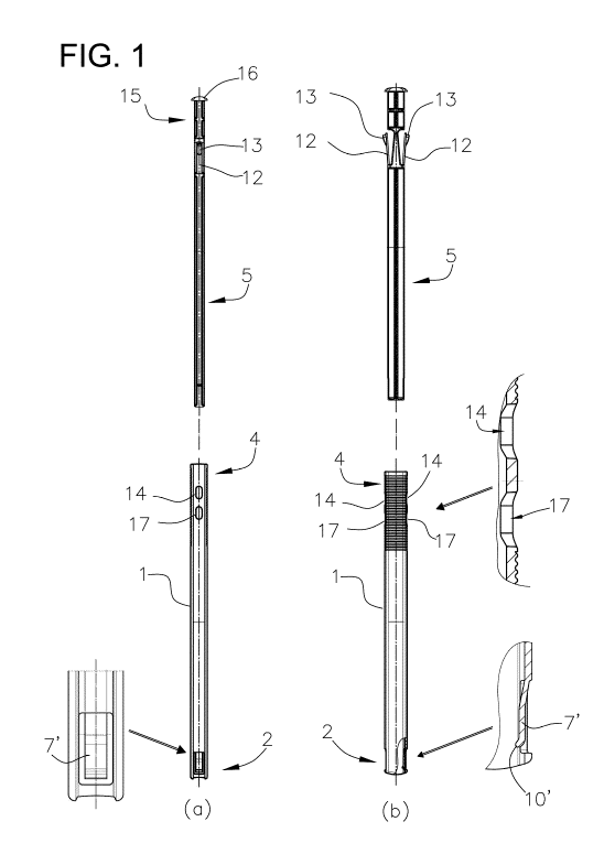
Figure 1 shows an exploded side view of an instrument for inserting a
suppository (a) from a
first side and (b) from the orthogonal side, three regions also shown
enlarged;
CA 02843351 2014-01-28
WO 2013/020922
PCT/EP2012/065270
8
Figure 2 shows a perspective view of the plunger part of the instrument of
Figure 1;
Figure 3 shows a perspective view of the front end of the tube part of the
instrument of
Figure 1;
Figure 4 shows a front view of the part shown in Figure 3, with a suppository
in place;
Figure 5 shows a longitudinal cross-section along the line 5-5 in Figure 4,
looking in the
direction of the arrows; and
Figure 6 shows in longitudinal cross-section the assembled instrument of
Figures 1 to 5 in
the three phases of operation (a) set for use, (b) part-way through pushing-in
of the plunger,
with the front end tongues beginning to splay, and (c) in the final condition
after ejection of
the suppository, in each case with the front end portion shown in enlarged
view for clarity.
Detailed Descrintion of the Drawings
Referring to the drawings, in which like parts are designated alike, there is
shown an
instrument for inserting a suppository, for example an intravaginal
suppository in round
tablet form. The illustrated embodiment embodies both aspects of the present
invention.
In general terms, the instrument comprises a tube 1, having a first end 2
adapted to receive
the suppository 3 and defining a forward end of the instrument in use, and a
second end 4
defining a rearward end of the instrument in use, and a plunger 5 disposed in
the tube 1 and
moveable therein to eject the suppository 3 from the forward end of the
instrument by
causing an action of pushing the suppository from behind. The tube 1 and the
plunger 5
have a generally rectangular transverse cross-section and the respective cross-
sectional
dimensions and shapes of the tube 1 and plunger 5 are complementary so that
the plunger 5
fits snugly and slidably in the tube 1 with no rotation.
The first end 2 of the tube 1 has an internal configuration which defines a
generally
rectangular space 6 for receiving the suppository 3.
CA 02843351 2014-01-28
WO 2013/020922
PCT/EP2012/065270
9
A pair of resiliently outwardly flexible members in the form of forwardly
directed tongues 7,
7' is provided at the first end 2 of the tube 1 and disposed to opposite sides
of the rectangular
space 6 to define the short sides of that rectangular space 6.
The pair of opposed tongues 7, 7' is resiliently moveable between a first
condition (shown in
Figures 3, 4 and 6(a)) in which the suppository 3 is prevented from exiting
the tube and a
second condition (shown in Figure 6(c)) in which the suppository 3 is
substantially not
prevented from exiting the tube. In the intermediate condition (shown in
Figures 5 and 6(b)),
a direct contacting cooperation is established between a cooperating shoulder
8 of each short
side of the front end of the rectangular plunger 5 and an internal tapering
face 9 of the
relevant one of the pair of opposed tongues 7, 7'. This direct contacting
cooperation, which
is not dependent on any action of the suppository 3 to splay the tongues 7, 7'
outwards,
continues because of the configuration of the shoulders 8 and the tapers 9 as
the plunger 5 is
pushed further into the tube 1 on actuating the instrument, that is, in going
from the
condition shown in Figure 6(b) to the condition shown in Figure 6(c).
The pair of opposed tongues 7, 7' is provided with internally directed lips
10, 10' which
assist in preventing the suppository 3 from exiting the tube until the tongues
7, 7' have been
splayed to a suitable extent.
Securement means are provided to secure the plunger 5 in the tube 1 at a first
position, prior
to actuation of the instrument, in which the suppository 3 is retained in the
space 6 defined in
the first end 2 of the tube 1, while allowing a user to manually release the
securement means
by pushing the plunger 5 to actuate the instrument. The securement means in
the illustrated
embodiment comprise a pair of mutually outwardly splayed, rearwardly directed,
and
mutually inwardly resiliently deformable, arms 12, provided on the shaft of
the plunger 5,
and each arm having at its free rearward end outwardly directed formations 13
which provide
in each case a surface that tapers inwards in the forward direction only, but
in the rearward
direction has a shoulder after the tapering surface.
These formations 13 are arranged to snap into a first pair of corresponding
apertures 14
provided in the wall of the tube 1, to cause the plunger 5 to be releasably
retained at the
desired first position prior to actuation of the instrument, as shown in
Figure 6(a).
CA 02843351 2014-01-28
WO 2013/020922
PCT/EP2012/065270
This enables the plunger to be releasably retained in the tube in the correct
position prior to
actuation, with the suppository in the position shown in Figures 4 and 6(a).
As shown in
Figure 6(a), the rearward end 15 of the plunger 5 projects from the tube 1
when the plunger 5
is in this position.
5
To actuate the instrument from this condition, the plunger 5 is pushed fully
into the tube, in
the direction of the arrow A in Figure 6(b). The tapering surfaces of the
formations 13 slide
over the rims of the apertures 14 so that the arms 12 flex inwardly offering
no or only little
resistance to the pushing of the plunger. As shown by the small arrows at the
front end of
10 the instrument illustrated in Figure 6(b), the pushing of the plunger 5
fully into the tube 1
causes the tongues 7, 7' to splay mutually outwards, in response to the
contacting
cooperation between the shoulders 8 and the tapering surfaces 9 as described
above. The
front face of the plunger 5 thus can push the suppository 3 from behind,
without substantial
resistance from the tongues 7, 7', so that the suppository is ejected from the
front end of the
tube as shown in Figure 6(c).
When the suppository 3 is ejected, that is, the plunger 5 is fully pushed into
the tube 1, a
circumferential stop flange 16 provided on the rear end of the plunger 5 abuts
the rear end of
the tube to limit the movement, as shown in Figure 6(c).
Further, at this point the formations 13 snap into a second pair of
corresponding apertures 17
provided in the wall of the tube 1, to cause the plunger to be retained at
this second, actuated,
position, as shown in Figure 6(c). The securement of the plunger at the fully
inserted
position in the tube 1 is thus indicative to the user that the suppository has
been ejected. The
fact that the plunger was consciously moved from the first position of
releasable retention to
the second position of full actuation, with corresponding snap sounds from the
arms 12 and
formations 13 engaging into the apertures 17, provides certainty that the
instrument was
properly actuated.
To reset the instrument for next use, the user may squeeze the arms 12
together and retract
the plunger 5 from the tube 1.
The foregoing broadly describes the present invention without limitation.
Variations and
modifications as will be readily apparent to those skilled in the art are
intended to be
included in the scope of the present invention as defined by the following
claims.