Note: Descriptions are shown in the official language in which they were submitted.
CA 02843716 2014-01-30
WO 2013/002893
PCT/US2012/037219
HYDROGEN GAS GENERATOR
FIELD OF THE INVENTION
[0001] This invention relates to a hydrogen gas generator, particularly a
hydrogen
generator for a fuel cell system.
BACKGROUND
[0002] Interest in fuel cell batteries as power sources for portable
electronic devices has
grown. A fuel cell is an electrochemical cell that uses materials from outside
the cell as the
active materials for the positive and negative electrode. Because a fuel cell
does not have to
contain all of the active materials used to generate electricity, the fuel
cell can be made with a
small volume relative to the amount of electrical energy produced compared to
other types of
batteries.
[0003] Fuel cells can be categorized according to the types of materials
used in the
positive electrode (cathode) and negative electrode (anode) reactions. One
category of fuel
cell is a hydrogen fuel cell using hydrogen as the negative electrode active
material and
oxygen as the positive electrode active material. When such a fuel cell is
discharged,
hydrogen is oxidized at the negative electrode to produce hydrogen ions and
electrons. The
hydrogen ions pass through an electrically nonconductive, ion permeable
separator and the
electrons pass through an external circuit to the positive electrode, where
oxygen is reduced.
[0004] In some types of hydrogen fuel cells, hydrogen is formed from a fuel
supplied to
the negative electrode side of the fuel cell. In other types of hydrogen fuel
cells, hydrogen
gas is supplied to the fuel cell from a source outside the fuel cell. A fuel
cell system can
include a fuel cell battery, including one or more fuel cells, and a hydrogen
source, such as a
fuel tank, a hydrogen tank or a hydrogen generator. In some fuel cell systems,
the hydrogen
source can be replaced after the hydrogen is depleted. Replaceable hydrogen
sources can be
rechargeable or disposable.
[0005] A hydrogen generator uses one or more reactants containing hydrogen
that can
react to produce hydrogen gas. The reaction can be initiated in various ways,
such as
hydrolysis and thermolysis. For example, two reactants can produce hydrogen
and
byproducts. An accelerator and/or a catalyst can be used to increase the rate
of reaction or
catalyze the reaction. When the reactants react, reaction products including
hydrogen gas and
byproducts are produced.
CA 02843716 2014-01-30
WO 2013/002893
PCT/US2012/037219
[0006] In order to minimize the volume of the hydrogen generator, volume
that is initially
occupied by the reactants can be used to accommodate reaction products as the
reactants are
consumed by arranging the components of the hydrogen generator in a volume
exchanging
configuration. As reactants are consumed, volume that they had occupied is
simultaneously
made available to contain reaction products.
[0007] The hydrogen gas is separated from byproducts and unreacted
reactants, and the
gas exits the hydrogen generator and is provided to the fuel cell battery.
Various means for
separating the hydrogen gas are known, including porous filters to separate
solids from the
hydrogen gas and gas permeable, liquid impermeable membranes to separate the
hydrogen
gas from liquids. Such means of separating the hydrogen gas can become filled
or blocked
by solids, thereby restricting or blocking the flow of hydrogen gas so the gas
cannot exit the
hydrogen generator.
[0008] It is desirable to provide a hydrogen generator capable of supplying
hydrogen gas
to a fuel cell stack with improved effectiveness and reliability of the
separation of hydrogen
gas from liquids and solids within the hydrogen generator. The hydrogen
generator is
advantageously less susceptible to internal restrictions or blockages that can
impede the
separation and release of the hydrogen gas. It is further desirable that the
hydrogen generator
have excellent reliability, safety, volume efficiency and a simple design that
is easily
manufactured at a low cost.
SUMMARY
[0009] The above objects are met and the above disadvantages of the prior
art are
overcome by a hydrogen generator and a fuel cell system as described below.
[0010] Accordingly, one aspect of the present invention is hydrogen
generator including a
housing; a liquid reservoir within the housing and including a liquid reactant
container, made
of a liquid impermeable material, and containing a liquid including a first
reactant; a reaction
area within the housing and including a reaction container, made of a liquid
impermeable
material, and within which the first reactant reacts to produce hydrogen gas
and byproducts; a
byproduct containment area within the housing and including a flexible
byproduct container,
made of a hydrogen permeable, liquid impermeable material through which solids
and liquids
cannot pass but through which hydrogen gas can pass; a hydrogen containment
area within
the housing and including a flexible hydrogen gas container, made of a
hydrogen
impermeable material, and configured to contain hydrogen gas from the
byproduct
2
CA 02843716 2014-01-30
WO 2013/002893
PCT/US2012/037219
containment area; and a hydrogen outlet from the hydrogen containment area
through the
housing. The byproduct containment area is in a volume exchanging relationship
with at
least one of the liquid reservoir and the reaction area.
[0011] The hydrogen generator can include one or more of the following
features:
= the byproduct container material is an elastic material, capable of
stretching and
contracting;
= the byproduct container material includes a fluoropolymer; the
fluoropolymer can include
an expanded fluoropolymer; the fluoropolymer can include a
polytetrafluoroethylene or a
polytetrafluoroethylene derivative;
= the hydrogen containment container material includes a metallized polymer
film or a
metal-polymer composite film;
= a catalyst configured to catalyze the reaction of the first reactant is
initially contained
within the reaction area;
= a second reactant is initially contained within the reaction area; the
second reactant can
include a chemical hydride, preferably a metal hydride, more preferably sodium
borohydride; the second reactant can be a solid; a solid pellet can include
the second
reactant; the solid pellet can further include a binder;
= the hydrogen generator includes an accelerant that is capable of
providing an increased
rate of reaction; the accelerant can include an acid;
= the reaction container includes an outlet through which hydrogen gas and
byproducts can
exit to the product containment area;
= the hydrogen generator further includes a pump configured to pump the
liquid from the
liquid reservoir to the reaction area; the pump can be disposed within the
hydrogen
generator; and
= a liquid dispersion device is disposed within the reaction chamber.
[0012] Another aspect of the invention is a fuel cell system including a
fuel cell stack and
a hydrogen generator as described above. The hydrogen generator can be
removable for the
rest of the fuel cell system.
[0013] These and other features, advantages and objects of the present
invention will be
further understood and appreciated by those skilled in the art by reference to
the following
specification, claims and appended drawings.
3
CA 02843716 2014-01-30
WO 2013/002893
PCT/US2012/037219
[0014] Unless otherwise specified, the following definitions and methods
are used herein:
= "effluent" means non-gaseous reaction products and unreacted reactants,
solvents and
additives;
= "expand" when used in describing a filter means for the filter material
to simultaneously
increase in volume, increase in porosity and decrease in density and pertains
only to the
material of which the filter is made;
= "initial" means the condition of a hydrogen generator in an unused or
fresh (e.g., refilled)
state, before initiating a reaction to generate hydrogen;
= "volume exchanging relationship" means a relationship between two or more
areas or
containers within a hydrogen generator such that a quantity of volume lost by
one or more
of the areas or containers is simultaneously gained by one or more of the
other areas or
containers; the volume thus exchanged is not necessarily the same physical
space, so
volume lost in one place can be gained in another place.
[0015] Unless otherwise specified herein, all disclosed characteristics and
ranges are as
determined at room temperature (20-25 C).
BRIEF DESCRIPTION OF THE DRAWINGS
[0016] In the drawings:
FIG. I is a schematic cross-sectional drawing of a hydrogen gas generator in
an initial state;
and
FIG. 2 is a schematic cross-sectional drawing of the hydrogen gas generator in
FIG. 1 in a
subsequent state.
DESCRIV1 ___________________________ ION
[0017] A hydrogen generator according to an embodiment of the present
invention
includes reactants that can react to produce hydrogen gas. One or more
reactants are
contained in a liquid stored in a reservoir within the housing. The liquid is
essentially stable
within the reservoir. The liquid is transferred to a reaction area, where the
reactants react. If
all reactants are contained in the liquid, reaction can be initiated by one or
a combination of
methods, such as contact with a catalyst, changing the pH of the liquid or
heating the liquid.
Alternatively, at least one reactant can be located elsewhere in the hydrogen
generator. For
example, if the other reactant(s) are contained in another liquid, the other
liquid can be stored
in another reservoir and be transferred to the reaction area to react with the
first liquid, or the
4
CA 02843716 2014-01-30
WO 2013/002893
PCT/US2012/037219
other liquid can be stored in the reaction area. If the other reactant(s) are
in solid form, they
can be stored within the reaction area.
[0018] When the reactants react, hydrogen gas and byproducts are produced
in the
reaction area and flow to the byproduct containment area. Some unreacted
reactants can be
carried to the byproduct containment area by the flow of hydrogen gas and
byproducts. To
minimize the amount of unreacted reactants in the byproduct containment area,
a screen or
other type of filter can be located near the exit from the reaction area to
help retain particles
of solid reactants within the reaction area, or additional liquid reactant can
be transferred to
the byproduct containment area or an intermediate area to react with unreacted
reactants
carried from the reaction area. Unreacted reactants can also continue to react
within the
byproduct containment area. A catalyst or accelerant can be included in the
byproduct
containment area to promote reaction of any unreacted reactants present.
[0019] During use of the hydrogen generator, reactants stored in reservoirs
and reaction
area are depleted so less volume is required for those areas. If the
containers for those areas
can become smaller as the contents are depleted (e.g., by collapsing or
shrinking), the volume
vacated by those areas becomes available to accommodate the increasing volume
of the
byproduct containment area, which has an expanding container. The byproduct
container is
made of a gas permeable and liquid impermeable to allow hydrogen gas but not
liquids and
solids in the byproduct containment area to pass therethrough, so that the gas
is separated
from the liquids and solids. Gas passing through the byproduct container is
collected within
the hydrogen containment area, which is contained within a container made of a
hydrogen
impermeable material until released through an outlet through the hydrogen
generator
housing.
[0020] A volume exchange between the product containment area and at least
one of the
liquid reservoir and the reaction area provides good volume efficiency, so
that the total
volume of the hydrogen generator does not have to be large enough to hold the
sum of the
volumes of the reactants plus byproducts, and the hydrogen generator can be
made as small
as possible.
[0021] Because the hydrogen containment area is essentially hermetically
sealed within
the hydrogen gas container, the hydrogen gas container can provide improved
resistance to
hydrogen gas leakage from the hydrogen generator, the housing may not have to
be made of a
hydrogen impermeable material, and the housing does not necessarily have to be
hermetically
CA 02843716 2014-01-30
WO 2013/002893
PCT/US2012/037219
sealed. This allows for the use of many different types of materials for the
housing, allows
the use of other housing sealing methods, and can simplify the hydrogen
generator
manufacturing process. Materials can be selected based on other desirable
properties such as
low cost, high strength, heat resistance, moldability, workability, and so on
without regard to
hydrogen impermeability. Examples of materials that may be considered include
plastics
(e.g., polyphenylene sulfides such as RYTON (Boedeker Plastics), polysulfones
such as
polyphenylsolfone, polysulfone and polyethersulfone, glass reinforced plastics
such as glass
fiber reinforced polyacrylamides such as DCEF (Solvay Advanced Polymers),
ceramics (e.g.,
silicon carbide, kaolinite and glass) and combinations thereof (e.g., metal
lined plastic). The
container can also be closed using fasteners, such as screws, rivets, nuts and
bolts, clips,
clamps, and so on, which may not be suitable if a hermetic seal is required,
and the use of
additional sealants, caulking, gaskets and so on may not be necessary. The
container can also
be closed using methods that may be capable of providing a hermetic seal, but
without the
process controls, etc., that may be necessary to insure the seal is hermetic.
A separate
container for the hydrogen containment area also facilitates reuse of the
hydrogen generator,
since the contents of a used hydrogen generator can be readily removed and
replaced.
[0022] Hydrogen gas can be provided by the hydrogen generator to a hydrogen
consuming apparatus such as a hydrogen fuel cell stack. The hydrogen consuming
apparatus
and the hydrogen generator can be incorporated into a system that includes
controls for
controlling the transfer of liquid from the liquid reservoir to the reaction
area of the hydrogen
generator.
[0023] The hydrogen generator can use a variety of reactants that can react
to produce
hydrogen gas. Examples include chemical hydrides, alkali metal silicides,
metal/silica gels,
water, alcohols, dilute acids and organic fuels (e.g., N-ethylcarbazole and
perhydrofluorene).
[0024] An alkali metal silicide is the product of mixing an alkali metal
with silicon in an
inert atmosphere and heating the resulting mixture to a temperature of below
about 475 C,
wherein the alkali metal silicide composition does not react with dry 02. Such
alkali metal
silicides are described in US Patent Publication 2006/0002839. While any
alkali metal,
including sodium, potassium, cesium and rubidium may be used, it is preferred
that the alkali
metal used in the alkali metal silicide composition be either sodium or
potassium. Metal
silicides including a Group 2 metal (beryllium, magnesium, calcium, strontium,
barium and
6
CA 02843716 2014-01-30
WO 2013/002893
PCT/US2012/037219
radium) may also be suitable. In an embodiment, sodium suicide can react with
water to
produce hydrogen gas and sodium silicate, which is soluble in water.
[0025] A metal/silica gel includes a Group 1 metal/silica gel composition.
The
composition has one or more Group 1 metals or alloys absorbed into the silica
gel pores. The
Group 1 metals include sodium, potassium, rubidium, cesium and alloys of two
or more
Group 1 metals. The Group 1 metal/silica gel composition does not react with
dry 02. Such
Group 1 metal/silica gel compositions are described in US Patent 7,410,567 B2
and can react
rapidly with water to produce hydrogen gas. A Group 2 metal/silica gel
composition,
including one or more of the Group 2 metals (beryllium, magnesium, calcium,
strontium,
barium and radium) may also be suitable.
[0026] As used herein, the term "chemical hydride" is broadly intended to
be any hydride
capable of reacting with a liquid to produce hydrogen. Examples of chemical
hydrides that
are suitable for use in the hydrogen generating apparatus described herein
include, but are not
limited to, hydrides of elements of Groups 1-4 (International Union of Pure
and Applied
Chemistry (IUPAC) designation) of the Periodic Table and mixtures thereof,
such as alkaline
or alkali metal hydrides, or mixtures thereof. Specific examples of chemical
hydrides include
lithium hydride, lithium aluminum hydride, lithium borohydride, sodium
hydride, sodium
borohydride, potassium hydride, potassium borohydride, magnesium hydride,
calcium
hydride, and salts and/or derivatives thereof. In an embodiment, a chemical
hydride such as
sodium borohydride can react with water to produce hydrogen gas and a
byproduct such as a
borate. This can be in the presence of a catalyst, heat, a dilute acid or a
combination thereof.
[0027] Chemical hydrides can react with water to produce hydrogen gas and
oxides,
hydroxides and/or hydrates as byproducts. The hydrolysis reaction may require
a catalyst or
some other means of initiation, such as a pH adjustment or heating. Chemical
hydrides that
are soluble in water can be included in the liquid reactant composition,
particularly at alkaline
pH to make the liquid sufficiently stable. The reaction can be initiated by
contacting the
chemical hydride solution with a catalyst, lowering the pH (e.g., with an
acid), and/or
heating. Chemical hydrides can be stored as a solid, and water can be added. A
catalyst or
acid can be included in the solid or liquid composition.
[0028] One or more catalysts can be used to catalyze the hydrogen producing
reactions.
Examples of suitable catalysts include transition metals from Groups 8 to 12
of the Periodic
Table of the Elements, as well as other transition metals including scandium,
titanium,
7
CA 02843716 2014-01-30
WO 2013/002893
PCT/US2012/037219
vanadium, chromium and manganese. Metal salts, such as chlorides, oxides,
nitrates and
acetates can also be suitable catalysts.
[0029] The rate of hydrogen generation can be controlled in a variety of
ways, such as
controlling of the rate at which liquid is transported to the reaction area,
adjusting the pH, and
making thermal adjustments. The rate of hydrogen generation can be controlled
to match the
need for hydrogen gas. A control system can be used for this purpose, and the
control system
can be within or at least partially outside the hydrogen generator.
[0030] Additives can be used for various purposes. For example, one or more
additives
can be included with a solid reactant as a binder to hold the solid material
in a desired shape
or as a lubricant to facilitate the process of forming the desired shape.
Other additives can be
included with a liquid or solid reactant composition to control pH. Such
additives include but
are not limited to acids (e.g., hydrochloric, nitric, sulfuric, citric,
carbonic, boric, carboxylic,
sulfonic, malic, phosphoric, succinic and acetic acids or combinations
thereof), or bases (e.g.,
hydroxides such as those of Group 1 elements, ammonium, and organic compounds;
metal
oxides such as those of Group 1 metals; and organic and metal amines).
Additives such as
alcohols and polyethylene glycol based compounds can be used to prevent
freezing of the
fluid. Additives such as surfactants, wetting agents and anti-foaming agents
(e.g., glycols,
polyglycols and polyols) can be used to control the liquid surface tension and
reaction
product viscosity to facilitate the flow of hydrogen gas and/or effluents.
Additives such as
porous fibers (e.g., polyvinyl alcohol and rayon fibers) can help maintain the
porosity of a
solid reactant component and facilitate even distribution of the reactant-
containing fluid
and/or the flow of hydrogen and effluents.
[0031] In one embodiment a chemical hydride such as sodium borohydride
(SBH) is one
reactant, and water is another reactant. The chemical hydride can be a
component of a liquid
such as water. The chemical hydride and water can react when they are exposed
to a catalyst,
an acid or heat in the reaction chamber. Alternatively, the chemical hydride
can be stored as
a solid in the reaction area, as essentially loose granules or powder or
formed into a desired
shape, for example. If an increased rate of reaction between the chemical
hydride and the
water is desired, a solid acid, such as malic acid, can be mixed with the
chemical hydride, or
acid can be added to the water. A chemical hydride can be formed into a mass,
such as a
block, tablet or pellet, to reduce the amount of unreacted chemical hydride
contained in the
effluent that exits the reaction area. As used below, "pellet" refers to a
mass of any suitable
8
CA 02843716 2014-01-30
WO 2013/002893
PCT/US2012/037219
shape or size into which a solid reactant and other optional ingredients are
formed. The pellet
should be shaped so that it will provide a large contact surface area between
the solid and
liquid reactants. In an example, a mixture including about 50 to 65 weight
percent SBH,
about 30 to 40 weight percent malic acid and about 1 to 5 weight percent
polyethylene glycol
can be pressed into a pellet. Optionally, up to about 3 weight percent
surfactant (anti-
foaming agent), up to about 3 weight percent silica (anti-caking agent) and/or
up to about 3
weight percent powder processing rheology aids can be included. The density of
the pellet
can be adjusted, depending in part on the desired volume of hydrogen and the
maximum rate
at which hydrogen is to be produced. A high density is desired to produce a
large amount of
hydrogen from a given volume, but high porosity enables a higher rate of
hydrogen
generation. On the other hand, if the pellet is too porous, unreacted SBH can
more easily
break away and be flushed from the reaction area as part of the effluent. One
or more pellets
of this solid reactant composition can be used in the hydrogen generator,
depending on the
desired volume of hydrogen to be produced by the hydrogen generator. The ratio
of water to
SBH in the hydrogen generator can be varied, based in part on the desired
amount of
hydrogen and the desired rate of hydrogen production. If the ratio is too low,
the SBH
utilization can be too low, and if the ratio is too high, the amount of
hydrogen produced can
be too low because there is insufficient volume available in the hydrogen
generator for the
amount of SBH that is needed.
[0032] It may be desirable to provide for cooling of the hydrogen generator
during use,
since the hydrogen generation reactions can produce heat. The housing may be
designed to
provide coolant channels. In one embodiment standoff ribs can be provided on
one or more
external surfaces of the housing and/or interfacial surfaces with the fuel
cell system or device
in or on which the hydrogen generator is installed or mounted for use. In
another
embodiment the hydrogen generator can include an external jacket around the
housing, with
coolant channels between the housing and external jacket. Any suitable coolant
can be used,
such as water or air. The coolant can flow by convection or by other means
such as pumping
or blowing. Materials can be selected and/or structures, such as fins, can be
added to the
hydrogen generator to facilitate heat transfer.
[0033] It may also be desirable to provide means for heating the hydrogen
generator,
particularly at startup and/or during operation at low temperatures.
9
CA 02843716 2014-01-30
WO 2013/002893
PCT/US2012/037219
[0034] The hydrogen generator can include other components, such as control
system
components for controlling the rate of hydrogen generation (e.g., pressure and
temperature
monitoring components, valves, timers, etc.), safety components such as
pressure relief vents,
thermal management components, electronic components, and so on. Some
components used
in the operation of the hydrogen generator can be located externally rather
than being part of
the hydrogen generator itself, making more space available within the hydrogen
generator
and reducing the cost by allowing the same components to be reused even though
the
hydrogen generator is replaced.
[0035] The hydrogen generator can be disposable or refillable. For a
refillable hydrogen
generator, reactant filling ports can be included in the housing, or fresh
reactants can be
loaded by opening the housing and replacing containers of reactants. If an
external pump is
used to pump liquid from the reservoir to the reaction area, an external
connection that
functions as a fluid reactant composition outlet to the pump can also be used
to refill the
hydrogen generator with fresh liquid. Filling ports can also be advantageous
when
assembling a new hydrogen generator, whether it is disposable or refillable.
If the hydrogen
generator is disposable, it can be advantageous to dispose components with
life expectancies
greater than that of the hydrogen generator externally, such as in a fuel cell
system or an
electric appliance, especially when those components are expensive.
[0036] The liquid reservoir, reaction area, byproduct containment area and
hydrogen
containment area can be arranged in many different ways. By arranging the
byproduct
containment area in a volume exchanging relationship with one or both of the
liquid reservoir
and the reaction area, the hydrogen generator can be more volume efficient and
provide a
greater amount of hydrogen per unit of volume of the hydrogen generator. Other
considerations in arranging the components of the hydrogen generator include
thermal
management (adequate heat for the desired reaction rate and dissipation of
heat generated by
the reactions), the desired locations of external connections (e.g., for
hydrogen gas, liquid
flow to and from an external pump), any necessary electrical connections
(e.g., for pressure
and temperature monitoring and control of fluid reactant flow rate), and ease
of assembly.
[0037] Liquid containing a reactant is initially disposed in the liquid
reservoir, which is
bounded by a container. The container is made of a liquid impermeable material
that is stable
in the environment of the hydrogen generator (e.g., nom-eactive with the
contents of the
reservoir). It can be either gas impermeable or gas permeable. A gas permeable
container
CA 02843716 2014-01-30
WO 2013/002893
PCT/US2012/037219
can allow small amounts of hydrogen that may be formed within the liquid
reservoir to
escape. While the container could be a rigid container, a flexible container
can become
smaller (e.g., by collapsing and/or contracting) as liquid is transferred out
of the reservoir, so
that space initially occupied by the reservoir can be made available to an
enlarging byproduct
containment area. Examples of types of flexible containers include containers
with walls
having accordion folds, similar to a bellows; elastic containers that can
stretch and contract in
response to changes in pressure like a balloon; and containers made of
nonelastic materials
that are not rigid but also do not stretch or contract to a great extent.
Examples of flexible,
films include polyethylene, polypropylene, polyvinylchloride, rubber, latex,
silicone, nylon,
Viton, polyurethane, neoprene, buna-N, polytetrafluoroethylene, expanded
polytetrafluoroethylene, perfluoroelastomers, and fluorosilicone. Of these,
rubber, latex,
silicone, Viton, neoprene, buna-N and perfluoroelastomers are generally
elastic, as well as
some polyvinylchloride and polyurethane films. All of these films are hydrogen
permeable to
at least some degree, and most are also generally liquid impermeable.
[0038] Liquid is transferred from the liquid reservoir to the reaction
area. This can be
done by one or more methods, including pressurizing the container and/or the
liquid within
the container, wicking the liquid to the reaction area and pumping the liquid.
Pressure can be
applied to the liquid or the liquid reactant container with a pressurized gas
within or outside
the liquid reactant container or a biasing component such as a spring,
compressed rubber or
compressed foam for example. Liquid can be wicked from one area to another by
a material
that is readily wetted by and can transport the liquid by capillary action.
The wicking
material can extend along the entire liquid transfer path from within the
liquid reservoir to
within the reaction area or along only a portion of the liquid transfer path.
A wicking
component can be made of, coated or lined with, or filled with the wicking
material. When
the liquid includes water, the wicking material can be a hydrophilic material
such as cotton,
polyester or nylon, for example. Liquid can also be pumped from the liquid
reservoir to the
reaction area using one or more pumps, which can be within or outside the
hydrogen
generator. Pumps are preferably as small as possible while being able to pump
sufficient
liquid for the hydrogen generator to supply hydrogen gas at the maximum
desired rate.
Locating pumps outside the hydrogen generator can allow more space for
reactants within the
housing and can reduce the total cost of a system with a disposable hydrogen
generator.
11
CA 02843716 2014-01-30
WO 2013/002893
PCT/US2012/037219
Examples of types of pumps that may be suitable include rotary, screw, piston,
diaphragm,
peristaltic pumps, centrifugal, radial flow, axial flow and impedance pumps.
[0039] The reaction area can be an area in which reactants come in contact
with each
other and/or with one or more reaction initiators such as catalysts, acid or
heat, and in which
the reactants react to produce hydrogen gas. As described above, all reactants
may be
included in one or more liquids, or one or more solid reactants can be
initially stored within
the reaction area. The reaction area is an area within the reaction container,
which can be a
rigid or flexible container, as described above for the liquid reactant
container. With a
flexible container the reaction area can participate in volume exchange with
the byproduct
containment area by becoming smaller as reactants initially stored within the
reaction area are
consumed. In addition, force applied to the reactants in a reaction area
within a flexible
container can facilitate good contact among reactants, reaction initiators and
additives, as
well as help to move hydrogen gas and byproducts out of the reaction area
toward the
byproduct containment area, to achieve good reactant utilization and hydrogen
generation
efficiency. In an embodiment, a solid reactant and optional additives are
formed into a solid
pellet that is initially disposed within the reaction area; a liquid including
another reactant is
transported to the reaction area, where it contacts the pellet, and a hydrogen
generating
reaction occurs. The reaction container in this embodiment can include an
elastic material
that is initially stretched and applies force against the pellet to minimize
space between the
pellet where liquid reactant and byproducts can accumulate. An elastic,
flexible or non-
elastic container can be wrapped with an elastic material (e.g., an elastic
film or band) or
biased by one or more springs or other biasing members.
[0040] A liquid disperser can be used to improve distribution of liquid
within the reaction
area. For example, the liquid disperser can include features such as one or
more nozzles
(e.g., spray nozzles), a tubular structure with one or multiple branches and
multiple liquid
outlets, a wicking member that can wick liquid over a large surface in contact
with another
reactant in the reaction area, and combinations thereof
[0041] The reaction container includes an outlet from which hydrogen gas
and
byproducts (gases, fluids and solids) can exit the reaction area. The outlet
can be just an
opening in the reaction chamber, an additional structure incorporated into the
container wall,
a screen or filter to retain large solid particles within the reaction area, a
valve or a
combination thereof
12
CA 02843716 2014-01-30
WO 2013/002893
PCT/US2012/037219
[0042] Unreacted reactants can be carried out of the reaction area by
hydrogen gas and
byproducts exiting therefrom. These reactants may continue to react after
leaving the
reaction area, e.g., in the byproduct containment area. This produces
additional hydrogen gas
and contributes to the total volume of hydrogen that the hydrogen generator
produces. In
order to maximize the possible hydrogen output, it can be advantageous to
transport some of
the liquid from the liquid reservoir to an area outside the reaction area
(e.g., to a portion of
the byproduct containment area or an intermediate area between the reaction
and byproduct
containment areas). This can be especially beneficial when unreacted reactants
include solid
particles, particularly if there is insufficient unreacted liquid reactant
present.
[0043] Hydrogen gas and byproducts from the reaction area enter the
byproduct
containment area, which has a byproduct container made of a material that is
liquid
impermeable but permeable to at least hydrogen gas. Preferably the container
is flexible so
that it initially encloses a small volume but expands to contain byproducts.
The container can
be similar to those described above for the reaction area and the liquid
reservoir, as long as it
is liquid impermeable and hydrogen permeable. Preferably the container has a
sufficient
hydrogen permeability to allow hydrogen gas to enter the hydrogen containment
area at a rate
adequate to meet the hydrogen gas demand. Because liquids and solids will not
permeate the
container, the container separates hydrogen gas from liquids and solids that
enter the
byproduct containment area. The byproduct container can have a large surface
area to both
provide a higher rate of hydrogen gas entry into the hydrogen containment
area. The large
surface area is also useful in preventing blockage of hydrogen transmission
through the
container due to accumulation of solids on the inner surface of the byproduct
container. This
is especially advantageous when byproduct and/or unreacted reactants can form
a crust that
can tend to restrict the transmission of hydrogen gas. Movement of a flexible
container can
also serve to fracture and/or strip accumulated solids as the byproduct
containment area
enlarges. It can also be advantageous for the byproduct container to be
elastic to further
contribute to breaking and removing solids from the surface of the container.
The initial size
of the byproduct containment area can be established based on factors such as
the initial
volume of liquid in the liquid reservoir, the initial volume of reactants and
additives in the
reaction area and the volume of byproducts that may be produced (the volume of
the
byproducts may be greater than the combined volume of the reactants).
13
CA 02843716 2014-01-30
WO 2013/002893
PCT/US2012/037219
[0044] To reduce the accumulation of solids on the inner surface of the
byproduct
container, one or more additional filters can be disposed in the byproduct
containment area to
remove a portion of the solids as the effluent from the reaction area passes
through the
byproduct containment area to the surface of the container. A series of
filters can be used and
arranged so the larger particles will be removed first. For example, the
general flow path
through the byproduct containment area may be through a coarser, more porous
filter first,
followed by successively finer, less porous filters, to prevent clogging of
the filters. Filters
with high stability, low reactivity with the effluent from the reaction area
are preferred.
Some types of filters can also be initially compressed and expand as the
byproduct
containment area expands, contributing to the volume efficiency of the
hydrogen generator or
being less resistant to clogging. Filters can be made of materials such as
nylon,
polytetrafiuoroethylene, polyolefins, carbon and other materials.
[0045] Hydrogen gas that passes through the byproduct container enters the
hydrogen
containment area, which is sealed within a hydrogen gas container made of a
hydrogen
impermeable material. The hydrogen gas container serves as a reservoir for
hydrogen gas
that is generated but not yet released from the hydrogen generator. This
provides a buffer
that can initially contain a small amount of hydrogen gas that can be provided
before
sufficient hydrogen has been produced during initial use and following
subsequent startups.
The hydrogen containment area can also contain hydrogen gas produced during
periods when
the release of hydrogen gas is halted, between stopping the transfer of liquid
to the reaction
area and the time at which reactants already in the reaction area (and
byproduct containment
area) are consumed and generation of hydrogen gas is halted. The size of the
hydrogen
containment area can be established based on factors such as the types of
reactants used, the
rate of hydrogen gas production, the volume of byproducts produced, the rate
at which
hydrogen gas is to be supplied and the amount of hydrogen gas desired to be
available at
startups.
[0046] The hydrogen gas container is impermeable with respect to hydrogen
gas, thereby
preventing leakage of hydrogen gas through the hydrogen generator housing,
without
requiring the walls of the housing to be impermeable with respect to hydrogen
gas and the
housing to be hermetically sealed. The internal hydrogen gas container can
provide a
redundant gas seal, adding to the safety and reliability of the hydrogen
generator. Hydrogen
impermeable materials include metalized polymeric films and metal-polymeric
composite
14
CA 02843716 2014-01-30
WO 2013/002893
PCT/US2012/037219
films such as laminates with polymeric and metal layers. Examples of suitable
polymeric
films include polyethyleneterephalate, polyvinylchloride, polyethylene,
polyearbonate,
polyimide, polypropylene and polyamide. Examples of suitable metals include
aluminum,
chromium, nickel and gold. An adhesive can be included on surfaces of the
material that are
sealed to make a sealed container. The entire inner surface can be a layer of
material that can
function as an adhesive. For example, polyethylene can be heat sealed. A
preferred type of
material is a laminate including three or more layers, with the middle layer
being a metal and
the outer layer being polymeric layers.
[0047] The hydrogen gas container encloses both the byproduct containment
area and the
reaction area. All hydrogen gas produced in the reaction area or downstream
therefrom
passes through the hydrogen gas container so the hydrogen gas is effectively
separated from
liquids and solids. The liquid reservoir can be disposed outside or within the
hydrogen gas
container. It can be advantageous for the liquid reservoir to be within the
hydrogen gas
container, especially if the liquid contains a hydrogen source that can react
during periods of
nonuse to produce small amounts of hydrogen gas, since this hydrogen gas can
also be
captured within the hydrogen gas container, thereby maximizing the hydrogen
gas output
from the hydrogen generator.
[0048] Hydrogen gas exits the hydrogen containment area through an outlet.
The
hydrogen gas container can be sealed to the outlet. The outlet can include one
or more valves
to seal the hydrogen generator when it is not providing hydrogen and to allow
hydrogen to
exit the hydrogen generator when desired.
[0049] Some reactants may contain or produce gaseous byproducts, and it may
be
desirable to remove these gases, especially if they can damage the hydrogen
consuming
apparatus being supplied with hydrogen. This may require additional filters,
etc., either
within the hydrogen generator or elsewhere in the system.
[0050] The hydrogen generator can include other features, such as a
pressure relief
mechanism to safely release excessive internal pressure due to an abnormal
condition.
[0051] The generation of hydrogen gas can be started and stopped by
starting and
stopping the transfer of liquid from the liquid reservoir to the reaction
area. This can be done
manually (e.g., with a manually operated switch) or automatically. Automatic
operation can
be accomplished with a control system, which can be disposed within or outside
the hydrogen
generator, or a combination thereof. Control can be based on the demand for
hydrogen, e.g.,
CA 02843716 2014-01-30
WO 2013/002893
PCT/US2012/037219
for a fuel cell system. In a fuel cell system, demand can be determined by
monitoring and/or
communicating with the fuel cell stack, an electric appliance being powered by
the stack, a
battery being charged by the stack, and so on.
[0052] The hydrogen generator can include thermal controls. For example,
heat can be
applied to assist in initiating the reaction, particularly at startup and when
the ambient
temperature is low. The hydrogen generator can be cooled if necessary to
remove excess heat
generated in the hydrogen generating reaction. Heating and cooling can be done
by a variety
of methods, including air convection, circulation of heating and cooling
fluids, electrical
heaters, and so on. A thermal control system can also include temperature
monitors, etc. The
thermal control system may be disposed within or outside the hydrogen
generator, or a
combination.
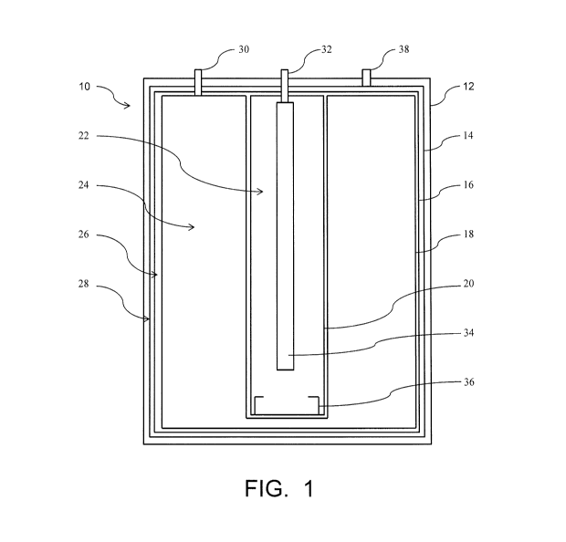
[0053] A hydrogen generator according to an embodiment is shown in FIGs. 1
and 2.
The embodiment shown can be further modified according to the above
description, to
include variations in such things as the types and initial locations of
reactants; the size, shape
and relative locations of individual components; and the incorporation of
optional features
and components into the hydrogen generator. FIG. 1 is a schematic
representation of a
hydrogen generator 10 in an initial condition, before use, and FIG. 2 is a
schematic
representation of the hydrogen generator 10 after at least partial use. The
hydrogen generator
includes a housing 12. Within the housing 12 is a reaction area 22 within a
reaction
container 20 and a liquid reservoir 24 within a liquid reactant container 20.
A liquid
containing a reactant such as water is initially contained in the liquid
reservoir 24. The liquid
can also contain another reactant, such as a chemical hydride dissolved
therein, in which case
reaction between the water and the chemical hydride is initiated within the
reaction area 22
after a quantity of the liquid is transferred from the liquid reservoir 24 to
the reaction area 22.
Alternatively, another reactant can be contained in a second liquid, initially
contained within
either the reaction area 22 or a second liquid reservoir (not shown) from
which it is
transferred to the reaction area 22; or a solid containing a reactant can be
initially contained
within the reaction area 22, in the form of one or more pellets for example.
Liquid is
transferred from the liquid reservoir 24 to the reaction area 22, where
reactants react to
produce hydrogen gas and byproducts. Liquid can be transferred from the liquid
reservoir 24
via an internal flow path (not shown) or via an external flow path from the
liquid reservoir
24, through a liquid reactant outlet 30 to a portion of the flow path outside
the hydrogen
16
CA 02843716 2014-01-30
WO 2013/002893
PCT/US2012/037219
generator 10, back into the hydrogen generator 10 through a liquid reactant
inlet 32 and into
the reaction area 22. The liquid can be dispersed within the reaction area 22
by a liquid
disperser 34. The reactants react within the reaction area 22, and hydrogen
gas and reaction
byproducts that are produced exit the reaction area 22 through a reaction area
outlet 36 and
enter a byproduct containment area 26 within a byproduct container 16. The
byproduct
container 16 is liquid impermeable and hydrogen permeable so liquids and
solids remain
within the byproduct containment area 26, while hydrogen gas passes through
the byproduct
container 16 into the hydrogen containment area 28. Hydrogen gas is released
from the
hydrogen generator 10 as needed, through a hydrogen gas outlet 38.
[0054] The byproduct containment area 26 can be in a volume exchanging
relationship
with one or both of the liquid reservoir 24 and the reaction area 22, as shown
in FIG. 2. As
the hydrogen generator 10 is used, liquid is transferred from the liquid
reservoir 24 and
hydrogen gas and byproducts exit the reaction area 22. Flexible containers 20
and 18 can
allow these areas to become smaller in volume, with a concurrent increase in
the volume of
the byproduct containment area 26. Initially the byproduct containment area 26
can be very
small, or it can be larger to accommodate a larger anticipated volume of
byproducts. The
byproduct containment area 26 can be in a volume exchanging relationship with
the hydrogen
containment area 28, if, for example, the byproduct container 16 is flexible
and able to move
in response to changes in the relative pressures applied by the contents of
the byproduct
containment area 26 and the hydrogen containment area 28.
[0055] All references cited herein are expressly incorporated herein by
reference in their
entireties. To the extent publications and patents or patent applications
incorporated by
reference contradict the disclosure contained in the present specification,
the present
specification is intended to supersede and/or take precedence over any such
contradictory
material.
[0056] It will be understood by those who practice the invention and those
skilled in the
art that various modifications and improvements may be made to the invention
without
departing from the spirit of the disclosed concept. The scope of protection
afforded is to be
determined by the claims and by the breadth of interpretation allowed by law.
17