Note: Descriptions are shown in the official language in which they were submitted.
CA 02843749 2014-01-30
WO 2013/028647
PCMJS2012/051645
SUSPENSION LINER WITH SEAL COMPONENT
[1] FIELD OF THE DISCLOSURE
[2] This disclosure relates to a suspension liner for prosthetic devices,
and
more particularly to a suspension liner for enveloping a residual limb and
having a
seal component for engaging a prosthetic socket.
[3] BACKGROUND
[4] Suspension liner systems are widely used in prosthetic systems for
residual
limbs in order to stabilize soft tissue, minimize pistoning or stretching,
assist
circulation of the residual limb and add comfort.
[5] Various solutions arc found in the prior art, including those described
in
U.S. patent no. 7,025,793, granted on April 11, 2006, and U.S. patent no.
8,034,120, granted on October 11,2011. According to these publications, a
liner
includes a liner body and a seal component located at the distal end area of
the
liner body. The seal component is flexible so it can conform to the shape of
the
residual limb and the internal wall of the prosthetic socket, thereby
providing an
airtight seal. The seal component minimizes movement of the limb within the
socket, so as to prevent pistoning and rotation. In operation, the residual
limb is
stepped into the socket and expels air through a distal valve on the socket so
as to
create hypobaric suction below the seal component.
[6] Some users find that known liners having sealing means fail to
sufficiently
tolerate volume fluctuations, and may leave pressure marks on the residual
limb
after periods of sustained use. Additional improvements may be required for
some users in that known liners do not adequately conform to the user's
anatomy,
and therefore fail to provide necessary comfort and skin protection. Moreover,
as
with all suspension liners having sealing means, it is necessary that the
liner
provides reliable suspension after an initial phase of volume and shape
conditioning after the liner is donned on the user's residual limb.
[7] SUMMARY
[8] A suspension liner with a seal component is described herein and
provides
a connection and interface between a prosthetic socket and residual limb. The
connection is made by using a suspension liner with a seal so as to create a
CA 02843749 2014-01-30
WO 2013/028647
PCMJS2012/051645
vacuum to suspend the residual limb to the socket. The suspension liner
removes
the need for distal pin that is commonly employed in suspension liners and is
used
to couple to a hard, prosthetic socket and other prosthetic leg components.
Moreover, because the seal is formed by the suspension liner itself, a sleeve
of an
exemplary type discussed in U.S. patent no. 6,592,539, granted July 15, 2003,
is
not required to seal the liner to the socket.
[9] The suspension liner with a seal component has at least the benefits of
mitigating distal pistoning from a distal pin. There is no restriction over
the knee
of the wearer to any sleeve. Therefore, the suspension liner with a seal
component
provides a reliable suspension without distal attachments or suspension
sleeves.
[10] Due to the particular liner and seal component embodiments discussed,
herein the suspension liner provides a secure connection over varying residual
limb volumes between the socket and the residual limb. Also, the liner and
seal
component embodiments provide a comfortable connection between the socket
and the limb by reducing noticeable pressure marks.
[11] According to an embodiment, the suspension liner includes an elongate,
generally conical liner body formed from at least one material segment that is
at
least radially elastically extensible from a relaxed non-extended condition
and
including proximal and distal end areas, and a seal component connected to the
liner body. The seal component has at least one exterior configuration for
engaging a prosthetic socket and at least one interior configuration for
movably
engaging the liner body.
[12] The exterior configuration may be arranged to have at least one seal that
protrudes radially outwardly from an exterior surface of the seal component
relative to a longitudinal axis of the liner body.
[13] The interior configuration may be arranged to protrude inwardly toward
the liner body, and may be yet further arranged to extend at an oblique angle
relative to the longitudinal axis of the liner body. In a variation, the
interior
configuration defines at least one blade extending obliquely toward the liner
body.
The blade may taper toward its distal and proximal ends along a segment of the
length of the liner body, such as tapering in thickness from an interior wall
of the
seal component toward the liner body exterior surface.
-2-
CA 02843749 2014-01-30
WO 2013/028647
PCMJS2012/051645
[14] A portion of the seal component carrying the interior configuration
extends
freely and movable relative to the liner body
[15] In a variation of the interior configuration of the seal component, the
seal
component defines an inwardly pitched portion at the proximal end thereof and
directed toward the liner body exterior surface.
[16] In another variation, the interior configuration defines at least one
blade
extending toward the liner body with the blade being bounded by an outwardly
pitched portion of the interior configuration located near a distal end of the
seal
component and an inwardly pitched portion at the proximal end of the seal
component and directed toward the liner body exterior surface.
[17] The seal component may define a base portion circumferentially secured to
an exterior surface of the liner body. The base portion may have an attachment
portion entirely secured to the exterior surface of the liner body, with the
remainder of the seal component outside and proximally located relative to the
attachment portion extending generally freely from the liner body.
[18] The seal component may define a lip arranged against the liner body; the
interior configuration may be located proximal relative to the lip. A
clearance
may be formed between the lip and an outwardly pitched portion of the interior
configuration extending from a base portion located at a distal end of the
seal
component.
[19] In another embodiment, the suspension liner includes an elongate,
generally conical liner body formed from at least one material segment that is
at
least radially elastically extensible from a relaxed non-extended condition
and
including proximal and distal end areas, and a seal component connected to the
liner body and having an exterior surface for engaging a prosthetic socket and
at
least one interior seal located along an interior surface of the seal
component and
arranged for engaging the liner body. A portion of the seal component carrying
the interior seal extends freely and movable relative to the liner body.
[20] The exterior seal may protrude from the exterior surface and extend
radially outwardly from the seal component relative to a longitudinal axis of
the
liner body and opposite to the interior seal. The at least one interior seal
can
define at least one blade extending obliquely toward the liner body. The seal
-3-
CA 02843749 2014-01-30
WO 2013/028647
PCT/1JS2012/051645
component may define a lip arranged against the liner body and the interior
seal is
located proximal relative to the lip.
[21] In yet another embodiment, the suspension liner has an elongate,
generally
conical liner body formed from at least one material segment that is at least
radially elastically extensible from a relaxed non-extended condition and
including proximal and distal end areas, and a seal component connected to the
liner body and having an exterior surface defining at least one exterior seal
protruding from the exterior surface and extending radially outwardly from the
seal component relative to a longitudinal axis of the liner body. The at least
one
interior seal is located along an interior surface of the seal component and
defines
at least one blade extending obliquely toward the liner body. A portion of the
seal
component carrying the interior seal extends freely and movable relative to
the
liner body.
[22] According to any of the suspension liner embodiments having a seal
embodiment, the seal component may be located at various locations along the
exterior surface of the liner body relative to the proximal and distal ends.
For
example, a "high profile" suspension liner may have a seal component which is
located 3-6 cm more proximally than a convention suspension liner with a seal
component. This particular configuration may be employed for those users that
require a more proximal seal, particularly trans-tibial amputees. By locating
the
seal component more proximally relative to the liner body, a larger vacuum
chamber is created distally of the seal component than in conventional
suspension
liners having a seal component. Moreover, the seal component may be located
proximal from a sensitive distal end of the residual limb.
[23] Any of the liner body embodiments described herein may define a
circumferential recess arranged to receive a length of the seal component. The
seal component may be fixedly secure to the liner without permitting
adjustment
of the location of the seal component relative to the liner body, or
alternatively the
seal component may be securable over any desirable location of the liner body
by
a clinician.
[24] The liner body may have a variable thickness. In an exemplary
embodiment, the liner body may have a significantly greater thickness at the
distal
-4-
CA 02843749 2014-01-30
WO 2013/028647
PCMJS2012/051645
end, and gradually taper toward the proximal end. In doing so, a
circumferential
recess of the liner body may define a reduced thickness region compared to
regions adjacently outside the circumferential recess.
[25] BRIEF DESCRIPTION OF THE DRAWINGS
[26] The numerous other advantages, features and functions of embodiments of
a suspension liner will become readily apparent and better understood in view
of
the following description and accompanying drawings. The following description
is not intended to limit the scope of the suspension liner, but instead merely
provides exemplary embodiments for ease of understanding.
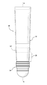
[27] Fig. 1 is an elevational view of an embodiment of a suspension liner
having
a seal component.
[28] Fig. 2 is an elevational view of the suspension liner without the seal
component.
[29] Fig. 3 is a cross-section view of the suspension liner according to
Fig. 2.
[30] Fig. 4 is a schematic view showing the seal component according to Fig.
1.
[31] Fig. 5 is a cross-section view of the seal component of Fig. 4 taken
along
line V-V.
[32] Fig. 6 is a sectional view corresponding to detail VI in Fig. 5.
[33] Figs. 7A-7E are schematic views showing the donning and doffing of the
suspension liner with a prosthetic socket.
[34] Fig. 8 is a schematic view showing minimization of the movement of the
residual limb in a socket.
[35] It should be noted that the drawing figures are not necessarily drawn to
scale, but instead are drawn to provide a better understanding of the
components
thereof, and are not intended to be limiting in scope, but rather to provide
exemplary illustrations. It should further be noted that the figures
illustrate
exemplary configurations of a liner, and in no way limit the structures or
configurations of a liner thereof according to the present disclosure.
-5-
CA 02843749 2014-01-30
WO 2013/028647
PCMJS2012/051645
[36] DETAILED DESCRIPTION OF VARIOUS EMBODIMENTS
[37] A better understanding of different embodiments of the invention may be
had from the following description read in conjunction with the accompanying
drawings in which like reference characters refer to like elements.
[38] A. Overview of Suspension Liner Embodiments
[39] In each of the embodiments discussed herein, the suspension liner is
intended for use between a residual limb and a prosthesis, such as a hard
socket,
and to be air-tight when donned over a residual stump. The internal surface of
the
liner may be formed of a layer of silicone elastomer, therefore serving as a
skin
interface. Silicone is advantageous in that it allows for different levels and
softness and strength to be incorporated into the liners of the present
application.
Moreover, silicone permits the addition of selected supplements, such as
petroleum jelly and aloe vera, which improve skin care and comfort.
[40] An elasticity controlling matrix material may be provided on the exterior
of the liner, the matrix material preferably being relatively compliant in a
radial
direction and substantially rigid or inelastic in an axial direction. The
matrix
material may extend over the distal or external side of the prosthesis, and is
advantageous in that it prevents movement of the liner when a prosthesis is
worn
thereover.
[41] A liner in accordance with this disclosure may be fabricated in a
sufficient
number of sizes to accommodate various sizes of residual limbs. In use, a
liner of
the type described herein is rolled up from the proximal to the distal end,
placed
over the distal end of the residual stump and rolled back up or "donned" over
the
stump like a stocking. This procedure and the benefits achieved thereby are
described in detail in U.S. patent no. 4,923,474, granted May 8, 1990. In
addition,
any of the liners and sleeves mentioned herein may be constructed in the
manner
prescribed by U.S. patent no. 4,923,474.
[42] The embodiments of the suspension liner of the present application may be
constructed according to the molding methods described in U.S. patent no.
6,485,776, granted November 26, 2002.
-6-
[43] B. Specific Embodiments of the Suspension Liner with a Seal
component
[44] Fig. 1 illustrates an embodiment of a suspension liner 10 in
accordance
with the invention. The liner 10 includes a liner body 12, and a seal
component
14 connected to the liner body 12.
[45] The liner body 12 preferably has an elongate, generally conical shape.
The liner body 12 defines a longitudinal axis A-A, and includes proximal and
distal end portions. The liner body 12 may be formed from at least one
material
segment that is at least radially elastically extensible from a relaxed non-
extended
condition.
[46] As depicted in Fig. 2, the liner body 12 is preferably formed with a
circumferential recess 16 for receiving the seal component. Particularly, the
recess 16 compensates for the thickness of the seal component in such a manner
that the seal component does not extend or substantially extend in excess or
at all
beyond an exterior surface ES of the liner body 12 located outside of regions
of
the recess 16. The seal component 14 may be secured against the exterior
surface
EE of the liner body located within the recess 16. Moreover, another exterior
surface EE located within the recess 16 is arranged for received a portion of
the
seal component, the base portion 20 described in Figs. 3 and 4, defines an
attachment portion that is adhered or otherwise fastened to the liner body 12.
[47] The liner body 12 forms a proximal beveled circumferential edge 17 at a
proximal end portion of the recess, a distal beveled edge 21 at a distal end
portion
of the recess, and a middle beveled circumferential edge 19 located between
the
proximal and distal end portions of the recess. The beveled edges receive
portions
of the seal component and minimize sharp or harsh edges that may cause
discomfort when the residual limb is in a socket with the liner donned.
[48] Fig. 1 generally shows the seal component 14 in a "conventional"
location,
however as also shown in Fig. 1, the seal component 14' can be located more
proximal relative to the liner body. For example, the seal component 14' may
be
located 3 to 6 cm more proximal than in the conventional location. This
particular
configuration may be employed for those users, particularly trans-tibial
amputees
that require a more proximal seal. By locating the seal component more
proximal
-7-
CA 2843749 2018-09-26
CA 02843749 2014-01-30
WO 2013/028647
PCT/1JS2012/051645
relative to the liner body, a larger vacuum chamber is created distally of the
seal
component than in conventional suspension liners having a seal component.
Moreover, the seal component may be located proximal from a sensitive distal
end
of the residual limb.
[49] The entire liner body 12 may be configured, including the recess 16 for
the
proximal seal component 14'
[50] Fig. 3 shows how the liner body may include a tapered thickness from the
distal end to the proximal end. For example, the distal end may have a
thickness
25 of 12-15 mm and taper in thickness 27 of 6-8 mm distally adjacent the
recess
16. The thickness 29 proximally adjacent the recess 16 may be 4-6 mm with the
thickness tapering to the proximal end to a thickness around 2.0-3.0 mm. The
thickness of the liner provides additional cushioning at the distal end, and
easy
roll-on/off at the proximal end when the liner is donned of doffed. Additional
thickness is about the recess to accommodate the seal component.
[51] In an exemplary embodiment, Figs. 4 and 5 show a seal component 14
having both exterior and interior configurations 18, 32. The exterior
configuration
18 is arranged for engaging against a prosthetic socket wall, whereas the
interior
configuration is arranged for engaging the exterior surface ES of the liner
body
12.
[52] The seal component 14 includes a base portion 20 located at the distal
portion of the seal component, and secures to the exterior surface EE of the
recess
16. An interior surface 36 of the base portion 20 is preferably anchored
circumferentially to the exterior surface EE to a pivot line 38. A seal wall
22 is
located above the pivot line 38, and flexibly and movably extends relative to
the
liner body 12 and the base portion 20.
[53] The seal component 14 defines a lip 40 which extends above the base
portion 20 and parallel to the exterior surface EE of the liner body 12. The
lip 40 is
adhered to the liner exterior surface EE, and provides additional retention of
the
seal component to the liner body. The lip may be tapered so as to provide a
gradual transition along the liner body.
[54] A gap 42 is formed between the lip 40 and a surface 44 of a distal
outwardly pitched portion 22 of the seal wall 24. The gap 42 enables the seal
wall
-8-
24 to flexibly and movably extend relative to the liner body. The distal
outwardly
pitched portion 22 effectively forms a taper for the seal component in order
to
facilitate donning of the suspension liner in a prosthetic socket.
[55] The seal wall 24 has exterior and interior surfaces 54, 56,
corresponding
respectively to the exterior and interior configurations 18, 32. The exterior
surface
54 carries a plurality of individual exterior radially extending seal rings
26, 28.
These seal rings 26, 28 are arranged to engage the interior socket wall, and
expel
air through a valve on the socket as the residual limb carrying the liner is
stepped
into the socket. The seal rings form an airtight connection between the liner
and
the socket, and ensure secure suspension.
[56] While two seal rings are shown in Fig. 4, the seal component may have
either one or any number of seal rings as considered necessary to form an
airtight
connection with a socket.
[57] According to Fig. 6, each of the seal rings 26, 28 includes a distal
pitched
section 50, a proximal pitched section 52, and a peak 48 located therebetween.
It
will be understood that the seal rings may take any number of configurations,
and
are not limited to the variation depicted in Fig. 5. Indeed, the seal rings
may be
construed in the manner of any one of the seal rings depicted and discussed in
U.S.
patent no. 8,034,120. For example, the pitched sections may have either a
linear,
cross-sectional profile, or a curved, cross-sectional profile. Further yet,
the seal
rings may take a variety of other cross-section profiles such as in the form
of a
square or with rounded edges.
[58] According to Fig. 5, the interior configuration 32 is formed along the
interior surface 56 of the seal wall 24, and is bounded by the distal
outwardly
pitched portion 22 and a proximal inwardly pitched portion 30 located at the
uppermost end of the seal component 14. As with the outwardly pitched portion
22, the inwardly pitched portion 30 acts as a transition to facilitate donning
and
doffing of the liner in a socket.
[59] A plurality of blades 34 are located along the interior surface 56 of
the seal
wall 24, and the plurality of blades 34 extend circumferentially about the
seal wall
24. The blades compensate for volume changes in the residual limb, by
expanding
-9-
CA 2843749 2018-09-26
CA 02843749 2014-01-30
WO 2013/028647
PCT/1JS2012/051645
and exerting pressure against an interior surface of the socket so as to
improve
suspension of the liner over known suspension liners with seals.
[60] In the depicted embodiment of Fig. 5, the blade has a smallest width
(direction of interior surface of seal wall toward the liner body) at a distal
portion
60, and gradually increases across a central portion 58 to a proximal portion
62.
The taper allows for a smooth transition of the interior seal to the distal
and
proximal end portions, thereby avoiding any sharp edges and avoiding any
pressure
points that may cause discomfort to the residual limb.
[61] The arrangement of the blade width may include other variations such as
the width of each of the blades tapering from a central portion 58 to a distal
portion
60, and likewise from the central portion 58 to a proximal portion 62. In
another
variation, the blade width may be substantially uniform from distal to
proximal
portions.
[62] Each blade has a greatest thickness closest to the interior surface 56 of
the
seal wall with a tapered thickness 46 as the blade extends toward the liner
body.
This configuration strengthens the blade at its interface with the seal wall
as well as
reduces any possible pressure points.
[63] In the variation shown in Fig. 5, each of the blades is arranged at an
oblique
angle relative to the longitudinal axis A-A of the liner. This arrangement
permits
the blades to expand outwardly as the liner is donned onto the residual limb
and
fold down toward the seal wall with some overlap over each of the blades as
the
liner is doffed. The blades are also arranged at an angle so as to ensure that
each
blade folds in a proper predetermined direction so as to avoid the creation of
any
pressure points.
[64] According to one variation, the blades extend at an angle approximately
at
27 degrees relative to the longitudinal axis of the liner body. This angle,
among
other angles as well, allows for the blades to be pressed inwards relative to
the liner
body when the liner is donned, and obtains a proper balance of force required
to
draw the blades outwardly when the liner is withdrawn from the socket. Because
the angle of the blades is arranged relative to the vertical axis of the liner
and is
combined with the orientation of the ends of the blades which press against
the
liner body, when a force is exerted to pull the liner out of a socket, the
blades
-10-
CA 02843749 2014-01-30
WO 2013/028647
PCMJS2012/051645
expand outwardly, which in turn creates extra pressure of the seal wall
against the
socket wall, thereby making it more difficult to lose suspension of the liner.
[65] It will be noted that the blades are not limited to an obliquely
extending
configuration, as explained in connection with Fig. 4, but the blades may be
arranged in any number of configurations such as being either generally
parallel or
perpendicular relative to the longitudinal axis A-A of the liner.
[66] The seal component is preferably formed as a separate element from the
liner body, and is securely attached thereto by appropriate bonding techniques
that
may include adhesive, heat seal, etc. The seal component may be constructed
from
a variety of materials, such as polymers, rubbers, coated textiles or any
other
suitable material. According to the embodiments, the seal component is
constructed from a silicone composition.
[67] While the seal component is described and depicted at the distal end
portion
of the liner, the seal component may be placed at any particular location
along the
exterior surface ES of the liner body.
[68] Turning to Figs. 7A-7E, the liner 10 carrying the seal component 14 is
shown worn on a residual limb RL and stepped into a prosthetic socket 100. As
the
residual limb RL is placed into the socket 100, the seal component 14 forms an
airtight seal with an interior surface of the socket 100 and urges air out of
the distal
end of the socket through a distally positioned expulsion valve 102. When it
is
desired to release the connection between the liner and the socket, the valve
is
released, and the residual limb can be removed from the socket.
[69] As shown in Fig. 8, the pressure is inversely proportional to the
suspension
force needed, so as to ensure stability and rotational control. The seal
component
14 forms a hypobaric sealing membrane that conforms to the shape of the
internal
socket wall, providing an airtight seal between the suspension liner and the
socket.
The recess in the liner body allows for there to be even pressure around the
seal in
the connection between the socket and liner. There is firm suspension, through
the
usage of the fins, to accommodate volume fluctuations of the residual limb.
[70] Of course, it should be understood that not necessarily all objects or
advantages may be achieved in accordance with any particular embodiment of the
invention. Thus, for example, those skilled in the art will recognize that the
-11-
CA 02843749 2014-01-30
WO 2013/028647
PCT/1JS2012/051645
invention may be embodied or carried out in a manner that achieves or
optimizes
one advantage or group of advantages as taught herein without necessarily
achieving other objects or advantages as may be taught or suggested herein.
[71] The skilled artisan will recognize the interchangeability of various
disclosed features. In addition to the variations described herein, other
known
equivalents for each feature can be mixed and matched by one of ordinary skill
in
this art to construct suspension liner in accordance with principles of the
present
invention.
[72] Although this invention has been disclosed in the context of certain
exemplary embodiments and variations thereof, it therefore will be understood
by
those skilled in the art that the present invention extends beyond the
specifically
disclosed embodiments to other alternative embodiments and/or uses of the
invention and obvious modifications and equivalents thereof. Thus, it is
intended
that the scope of the present invention herein disclosed should not be limited
by the
particular disclosed embodiments described above.
-12-