Note: Descriptions are shown in the official language in which they were submitted.
CA 02844074 2014-02-28
CA Application
Slakes Ref: 71858/00018
1 ASSEMBLY FOR TRANSFERRING FLUIDS BETWEEN A VESSEL AND A TURRET
2 STRUCTURE MOUNTED IN SAID VESSEL
3
4 FIELD OF THE INVENTION
The invention relates to an assembly for transferring fluids between a vessel
and a turret
6 structure mounted in said vessel for a rotation around a substantially
vertical turret axis, wherein
7 said turret structure comprises a swivel having at least one fluid path
and wherein the fluid path
8 is connected with one end of a fluid piping of which the second end is
connected to the vessel.
9
BACKGROUND OF THE INVENTION
11 It is noted that the indication "vessel" also may refer to parts or to a
structure fixed to the
12 vessel.
13 It is known in the offshore industry (and especially the production of
fluids such as oil or
14 gas) to use vessels comprising a turret structure mounted in a moon pool
for a rotation around a
substantially vertical turret axis. The turret structure (or a disconnectable
buoy connected to a
16 lower part thereof) may be moored to the seabed by mooring lines and
connects risers through
17 which the fluid is delivered to a fluid inlet in the geostationary part
of the swivel, which typically
18 is mounted on top of the turret structure or on top of a so-called
turntable which is based on and
19 forms part of the turret structure. The fluid is transferred from the
rotating part of the swivel to
appropriate equipment on board of the vessel through fluid piping connecting
the swivel fluid
21 outlet with the vessel (for example a so-called turret access structure,
TAS). It is noted that the
22 fluids can be transferred in two directions, both from the risers to the
vessel and vice versa. For
23 clarity only the direction towards the vessel is mentioned here, but it
should be realised that the
24 indications "inlet" and "outlet" are interchangeable.
The turret structure, including its turntable, the swivel as well as the
vessel (for example
26 the TAS) often are subject to considerable loads tending to deform said
components. The loads
27 can originate from, among others, gravity, motions, accelerations,
vessel deformations,
28 temperature differences, pressure, mooring forces, riser forces, waves,
current and wind.
29 Because these components generally have a different stiffness and will
be subjected to different
loads, their deformations will be different causing relative displacements
between these
31 components.
1
22515513.1
CA 0 2 8 4 4 0 7 4 2 0 14-0 2-2 8
CA Application
Slakes Ref: 71858/00018
The relative deformations between the rotating part of the swivel and the
vessel (or TAS)
2 deform the fluid piping between them, which causes stresses on the swivel
and its outlets.
3 These stresses can be low when the piping is flexible and it thus easily
conforms to the relative
4 deformations, but can also be very high when the piping is substantially
rigid, for example for
high pressure piping with a large diameter. These stresses can interfere with
the operation of
6 the swivel, for example by damaging it or causing its seals to leak.
7 Known practice for reducing the mentioned stresses is to increase the
flexibility of the
8 fluid piping (for example by allowing multiple bends in the fluid piping
with long piping sections
9 between successive bends), together with anchor points for the fluid
piping sufficiently far away
from the swivel. However, adding such fluid piping lengths is expensive and
increases the
11 overall weight acting on top of the vessel or TAS, further increasing
the detrimental deformation
12 thereof with resulting increase of the relative deformation between the
vessel (or TAS) and the
13 swivel.
14 Another known practice for reducing these stresses is to increase the
stiffness of the
components (such as the turret structure and the TAS) in order to reduce their
(relative)
16 deformations. This, however, involves the use of extra material (such as
steel) with an
17 associated increase of cost and weight.
18 The effectiveness of the above known stress reduction methods decreases
when the
19 structures (TAS, vessel, turret, swivel etc) increase in size. Larger
structures will undergo larger
relative deformations, while more steel is required to stiffen them and/or
more piping bends and
21 lengths are needed to accommodate the relative deformations. This
becomes prohibitive in
22 terms of the required amount of constructive material (steel, piping),
mass and cost,
23 In view of the above it is an object of the present invention to provide
an improved
24 assembly of the type referred to above.
26 SUMMARY OF THE INVENTION
27 Thus, in accordance with the present invention the assembly further
comprises a flexible
28 bridge member connecting a part of the turret structure with the vessel,
wherein a rotation of
29 said part of the turret structure around the turret axis is
substantially locked to the rotation of the
vessel while a relative displacement between said part of the turret structure
and the vessel is
2
22515513,1
CA 0 2 8 4 4 0 7 4 2 014-0 2-2 8
CA Application
Blakes Ref: 71858/00018
1 allowed, and wherein said bridge member supports the fluid piping to
substantially take away
2 the loads from the fluid piping on the said swivel and its outlets,
3 The part of the turret structure connected to the vessel by the bridge
member for
4 example may be the rotating parts of the swivel. The bridge member may
support the fluid
piping in a manner allowing a relative displacement between the bridge member
and the fluid
6 piping.
7 It is noted that "locked to the rotation of the vessel" does not exclude
the possibility of a
8 (moderate) limited relative rotation between said part of the turret
structure and the vessel (the
9 allowable magnitude of which may depend from, among others, the
flexibility of the fluid piping).
As a result of the provision of such a bridge member a substantially fixed
anchor point is
11 provided on the bridge member for the flexible fluid path between the
swivel and the vessel
12 (such as a TAS) which can take the piping loads from the relative
deformations between
13 components without the need for increasing the stiffness of such
components and without
14 adding extra lengths of fluid piping or extra bends, such that a minimal
functional piping layout is
sufficient.
16 In a preferred embodiment of the assembly the bridge member is provided
with at least
17 one hinge member for allowing said relative displacement between said
part of the turret
18 structure and the vessel or the structure fixed to the vessel. For
example, such a hinge member
19 may be positioned at an end of the bridge member connecting to said part
of the turret structure
or connecting to the vessel or the structure fixed to the vessel, or the at
least one hinge member
21 may be positioned intermediate two opposite ends of the bridge member.
The use of such a
22 hinge member provides the required flexibility of the bridge member
which otherwise may be
23 constructed as a rigid part, while the bridge member nevertheless
maintains its ability for an
24 effective support of the fluid piping to take away the loads from the
fluid piping on the said
swivel and its outlets.
26 It is possible that the hinge member is defined by a classic hinge (for
example
27 comprising two parts connected by a hinge axis) or by a weakened part of
the bridge simulating
28 a hinge (for example specially oriented plating allowing a relative
movement between parts
29 connected thereto),
In another embodiment the bridge member is sufficiently long for achieving its
flexibility
31 for allowing said relative displacement between said part of the turret
structure and the vessel or
3
22515513.1
CA 0 2 8 4 4 0 7 4 2 014-0 2-2 8
CA Application
Blakes Ref. 71858/00018
1 the structure fixed to the vessel without the need for hinge members. Of
course, such an
2 embodiment also may be combined with the use of hinge members, if
required.
3 In another embodiment of the assembly according to the present
invention, said part of
4 the turret structure (to which the bridge member is connected) is a
swivel tower mounted around
the swivel and engaging the remainder of the turret structure by means of a
swivel tower
6 bearing, such that the swivel tower does not follow a rotation of the
remainder of the turret
7 structure around the turret axis. In this embodiment the swivel tower
also could be seen as a
8 part of the bridge member. The swivel tower bearing supports the swivel
tower in all directions
9 but the swivel tower maintains its orientation with respect to the
vessel. Because, now, both the
swivel tower and swivel are mounted on the turret structure, relative
deformations between the
11 swivel fluid outlet and the swivel tower are minimised (and therefore
also relative deformations
12 between the swivel and the bridge member which is connected to the
swivel tower).
13 This swivel tower also serves to provide access to the swivel for
maintenance,
14 inspection etc.
In one embodiment the bridge member engages the swivel tower in such a manner
that
16 a rotation of the swivel tower around the turret axis is locked to the
rotation of the vessel.
17 As an alternative or additionally, the swivel tower is connected to the
vessel by a torsion
18 lock mechanism which substantially ensures that the swivel tower and the
vessel rotate in
19 unison. Thus, such a torsion lock mechanism may prohibit a rotation of
the swivel tower around
the turret axis relative to the vessel. Said torsion lock mechanism may be
passive or active.
21 Because, as explained above, the relative deformations between the
swivel fluid outlet
22 and the swivel tower are minimised, it is possible that the fluid piping
is attached to the swivel
23 tower in a stationary (substantially rigid) manner without causing
substantial piping loads on the
24 said swivel and its outlets. For example fluid piping support points may
be placed on the swivel
tower to relieve deformation loads (acting in the fluid piping and caused by
the relative
26 displacements between components, as elucidated before) on the swivel.
27 In case the relative deformations between the swivel fluid outlet and
the swivel tower are
28 still significant, for example when their axes of rotations are slightly
misaligned, a pipe loop can
29 be placed in or around the swivel tower. This loop has sufficient
flexibility to accommodate their
relative deformations without introducing unacceptable stresses on the swivel.
4
22515513.1
CA 0 2 8 4 4 0 7 4 2 0 14-0 2-2 8
CA Application
Blakes Ref: 71858/00018
1 The swivel tower bearing may be located above, below or substantially at
the level of a
2 fluid inlet of the swivel. Such a fluid inlet also is referred to as an
inlet collector.
3 In yet another embodiment of the assembly using a swivel tower, the
bridge member or
4 part thereof is capable of a rotation around a vertical axis. In such an
embodiment the rotation of
the swivel tower is substantially locked to the rotation of the vessel, albeit
to a lesser degree
6 than in the other embodiments. This allows the use of a bridge member
with improved
7 characteristics and simplified constructive layout.
8 For example, the bridge member may be connected to said structure fixed
to the vessel
9 through a universal joint, such as for example a ball joint, allowing
rotations but preventing
translations of the bridge member relative to said structure fixed to the
vessel. The bridge
11 member then may be rather stiff providing a good support for the fluid
piping whilst the said
12 structure can be constructed as a less complicated frame which is not
loaded by torsion forces.
13 As an alternative the bridge member itself may comprise such a universal
joint between two
14 adjacent bridge member parts, of which a first one is directly connected
to the vessel and the
second one is connected to the respective part of the turret structure (for
example the swivel
16 tower).
17 In an embodiment the swivel tower bearing is positioned on a swivel base
part, which
18 may be enlarged. Thus there may be provided a swivel base part with a
diameter which is larger
19 than the diameter of the remainder of the swivel, wherein the swivel
tower bearing is positioned
on said swivel base part. This increases the stability of the swivel tower
(with respect to the
21 swivel) and further reduces deformations between the swivel and the
swivel tower.
22 It is also possible to conceive embodiments in which no swivel tower is
present, but in
23 which said part of the turret structure (to which the bridge member is
connected) is defined by
24 the rotating part(s) of the swivel.
Again, in such an embodiment it is conceivable that the bridge member engages
the
26 rotating parts of the swivel in such a manner that their rotation around
the turret axis is
27 substantially locked to the rotation of the vessel (and thus they rotate
in unison with the vessel),
28 or (additionally or not) that the rotating parts of the swivel are
connected to the vessel by a
29 torsion lock mechanism.
5
22515513.1
CA 0 2 8 4 4 0 7 4 2 014-0 2-2 8
CA Application
Blokes Ref: 71858/00018
1 BRIEF DESCRIPTION OF THE FIGURES
2 Hereinafter the invention will be elucidated while referring to the
drawing, in which:
3 Figure 1 schematically shows a state of the art assembly;
4 Figure 2 schematically shows a first embodiment of the assembly
according to the
present invention;
6 Figure 3 shows a cross-section according to A-A in figure 2;
7 Figure 4 schematically shows a second embodiment of the assembly
according to the
8 present invention;
9 Figure 5 schematically shows a third embodiment of the assembly
according to the
present invention;
11 Figure 6 shows a cross-section according to B-B in figure 5;
12 Figure 7 schematically shows a fourth embodiment of the assembly
according to the
13 present invention;
14 Figure 8 shows a cross-section according to C-C in figure 7;
Figure 9 schematically shows a fifth embodiment of the assembly according to
the
16 present invention;
17 Figure 10 shows a cross-section according to D-D in figure 9, and
18 Figure 11 shows a cross-section according to E-E in figure 9.
19
DESCRIPTION OF THE PREFERRED EMBODIMENTS
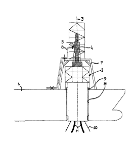
21 Firstly referring to figure 1, a state of the art assembly is
illustrated for transferring fluids
22 between a vessel 1 and a turret structure 2 mounted in said vessel for a
rotation around a
23 substantially vertical turret axis 3. In its upper part the turret
structure 2 comprises a swivel 4
24 having at least one fluid outlet 5 which is connected to one end of a
fluid piping 6 of which the
second end is connected to the vessel 1 or to a structure 7 (for example a so-
called turret
26 access structure TAB) fixed to the vessel.
27 The turret structure 2 is mounted in a moonpool 8 by means of a turret
bearing 9 and is
28 moored to the seabed by mooring lines 10. Risers 11 extend from the
seabed through the turret
6
22515513.1
CA 0 2 8 4 4 0 7 4 2 0 14-0 2-2 8
CA Application
Slakes Ref: 71858/00018
1 structure and are connected to a lower part (swivel fluid inlet, not
shown in detail) of the swivel
2 4, whether or not through a process manifold.
3 The turret structure 2 allows the vessel to weathervane around the
turret structure, as is
4 generally known. The lower part of the turret structure 2 may be embodied
as a disconnectable
buoy part, as is generally known.
6 As will appear from the following description of embodiments of the
assembly according
7 to the invention while referring to figures 2-11, such an assembly
further comprises a flexible
8 bridge member 12 connecting a part of the turret structure 2 with the
vessel 1 or a structure 7
9 fixed to the vessel. The assembly is constructed in such a way that a
rotation of said part of the
turret structure 2 around the turret axis 3 is substantially locked to the
rotation of the vessel
11 while a relative displacement between said part of the turret structure
and the vessel or the
12 structure fixed to the vessel is allowed, and wherein said bridge member
12 supports the fluid
13 piping 6 in a manner allowing a relative displacement between the bridge
member and the fluid
14 piping.
Firstly referring to figure 2, a bridge member 12 is shown comprising a
vertical part 13
16 mounted to the vessel 1 through a hinge member 14 for allowing said
relative displacement
17 between said part of the turret structure 2 (a swivel tower 17 as will
appear later) and the vessel
18 1. The bridge member further comprises a horizontal part 15 which
connects the vertical part 13
19 with said part of the turret structure. As seen in figure 3, the
horizontal part 15 may be
constructed from a number of interconnected bars 15', of which (in the
illustrated embodiment) a
21 central bar supports the fluid piping 6, preferably in a manner (guide
21) allowing a relative
22 displacement between said bar 15' and the fluid piping 6. Likewise the
vertical part 13 will
23 support the fluid piping 6 in a corresponding manner (guide 22).
24 Although not shown, the hinge member 14 also may be positioned
intermediate the
vertical and horizontal parts 13, 15, respectively, of the bridge member 12 or
at the opposite end
26 thereof connecting to the turret structure 2. Multiple hinge members may
be provided too at
27 different locations. Each hinge member 14 may be defined by a classic
hinge (as illustrated) or
28 by a weakened part (of the bridge member or a component connected
therewith) simulating a
29 hinge (for example a deformable plate 16 between the vertical and
horizontal bridge member
parts 13 and 15).
7
22515513.1
CA 0 2 8 4 4 0 7 4 2 014-0 2-2 8
CA Application
Slakes Ref. 71858/00018
1 As illustrated in figure 2, said part of the turret structure 2 to which
the bridge member 12
2 connects, is a swivel tower 17 mounted around the swivel 4 and engaging
the remainder of the
3 turret structure 2 by means of a swivel tower bearing 18. The swivel 4
may comprises a swivel
4 base part 34 with a diameter which is larger than the diameter of the
remainder of the swivel,
wherein the swivel tower bearing 18 is positioned on said swivel base part.
The swivel tower
6 bearing typically may be a roller type or sliding type bearing.
7 The bridge member 12, in one embodiment, engages the swivel tower 17 in
such a
8 manner that rotation of the swivel tower around the turret axis 3 is
substantially locked to the
9 rotation of the vessel. As a result the swivel tower 17 does not (or only
in a very limited sense)
follow a rotation of the remainder of the turret structure 2 around the turret
axis 3.
11 In the illustrated embodiment the fluid piping 6 is attached to the
swivel tower 17 in a
12 stationary manner, as illustrated by at least one support member 19. The
position of such a
13 support member, however, may vary and for example may be located on the
bridge member 12.
14 Further, such a support member also may provide a support allowing a
moderate movement of
the fluid piping 6. Correspondingly, the fluid piping may be attached to the
vessel 1 (support
16 member 20).
17 Figure 3 further illustrates swivel driver arms 35 connecting part of
the swivel to the
18 swivel tower,
19 Figure 4 illustrates a second embodiment. The bridge member 12 now is
supported by a
structure 23 fixed to the vessel (for example a module), but otherwise closely
resembles the
21 bridge member of the previous embodiment. However, in this embodiment
the swivel tower 17
22 is connected to the vessel 1 (or an auxiliary structure 1' thereof) by a
torsion lock mechanism 33
23 (active or passive) for prohibiting a rotation of the swivel tower 17
around the turret axis 3. Thus.
24 in this embodiment the bridge member 12 is not required to provide such
a prevention of a
rotation of the swivel tower 17 (but may or may not carry out such a
function).
26 Figures 5 and 6 show an embodiment of the assembly in which the bridge
member 12
27 has a different layout. It comprises a horizontal part 24 (in this
embodiment comprising bars 24')
28 connecting with its one end to the swivel tower 17 and provided at its
other end with a hinge
29 mechanism 25 through which it is connected to a structure 27.
8
22515513.1
CA 0 2 8 4 4 0 7 4 2 014-0 2-2 8
CA Application
Blakes Ref: 71855100018
1 It is noted that in this embodiment it is also possible to say that the
bridge member 12
2 comprises said horizontal part 24 and a vertical part 27 fixed to the
vessel, with the hinge
3 mechanism 25 in between said parts. This is merely a matter of
definition.
4 Figures 7 and 8 illustrate an embodiment in which there is no swivel
tower, but in which
the rotating parts of swivel 4 defines said part of the turret structure 2 to
which the bridge
6 member 12 is connected. In this embodiment the bridge member 12 engages
the rotating parts
7 of the swivel 4 in such a manner that their rotation is substantially
locked to the rotation of the
8 vessel. There actually are two bridge members 12 illustrated one above
the other, each
9 connected to the swivel 4 and comprising a structure 28, in a manner
substantially
corresponding to the previous embodiment and thus not elucidated here. It is
noted, however,
11 that such multiple bridge members 12 (of which there also may be
provided only one or more
12 than two, depending on the amount of fluid piping 6) may support a
multitude of fluid piping 6
13 and may be separated (as shown) or combined (for example stacked one on
top of the other),
14 The fluid piping 6 may be connected to the bridge member 12 using
support members 29,
whereas guides 30 allow a relative movement between the structure 28 (which is
considered to
16 be a part of the bridge member 12) and the piping 6.
17 Figures 9-11, finally, illustrate an embodiment of the assembly
according to the present
18 invention, wherein a bridge member 12 is capable of a rotation around a
vertical axis 26 defined
19 by a structure 30 which is fixed to the vessel 1. The rotation may occur
through a universal joint,
such as for example a ball joint, allowing more rotations than only around a
vertical axis 26 but
21 preventing translations of the bridge member 12 relative to said
structure 30 which is fixed to the
22 vessel 1. As a result the bridge member 12 may be carried out relatively
stiff, whereas the
23 structure 30 will be free from swivel tower induced torsion loads and
thus may be constructed
24 less heavy.
it is noted that the bridge member in this embodiment also may be considered
26 comprising the illustrated horizontal part 12 and the structure 30, with
interposed universal joint.
27 In this embodiment it is also possible to omit the swivel tower 17, or
to connect the
28 swivel tower 17 to the vessel by a torsion lock mechanism 33 (see figure
4) in order to lock the
29 rotation of the rotating parts of the swivel 4 to the rotation of the
vessel 1 around the turret axis
3.
9
22515513.1
CA 0 2 8 4 4 0 7 4 2 0 14-0 2-2 8
CA Application
Blokes Ref: 71858/00018
1 The invention is not limited to the embodiments described above which
may be varied
2 widely within the scope of the invention as defined by the appending
claims.
22515513.1