Note: Descriptions are shown in the official language in which they were submitted.
WO 2013/028717 CA 02844113 2014-02-03
PCT/US2012/051789
METHOD OF AND APPARATUS FOR DETECTING DEFECTS
CROSS-REFERENCE TO RELATED APPLICATIONS
[0001] This application claims the benefit of co-pending application
Serial No.
61/526,094, filed on August 22, 2011, entitled ULTRASONIC INSPECTION SYSTEM.
FIELD
[0002] The present invention generally relates to a method of and
apparatus for
detecting defects in a structure and, more particularly, to a method of
perfouning
nondestructive-type testing in situ using ultrasonic transducers to detect
flaws and defects
in a railway rail.
BACKGROUND
[0003] The United States Federal Railroad Administration has published
statistics which indicate that train accidents caused by track failures
including rail, joint
bar and anchoring resulted in approximately 1,300 derailments from 2001 to
2011. The
primary cause of these track failures was defects and fissures in the rail
head.
[0004] During their normal use and as would be expected, the rail
portions of
most track structures will be subjected to severe, and uncontrollable
environmental
conditions. These severe environmental conditions, over a relatively long
period of time,
may ultimately result in such rail developing certain detrimental flaws.
[0005] In addition, in today's modem railroad industry, the rail portion
of such
track structures will quite often be required to support rather heavy loads
being carried by
modern freight cars. Furthermore, these heavy loads are travelling at
relatively high
speeds. It would not be uncommon for these freight cars, when they are fully
loaded with
cargo, to weigh up to generally about 125 tons. Such relatively heavy loads
and high
speeds can, also, result in undesirable damage to such rail portions of the
track structure.
Such damage, for example, may include stress fractures.
[0006] It would be expected, therefore, that if these detrimental
defects were
not timely detected and, likewise, if they are left unrepaired such defects
could lead to
some rather catastrophic disasters, such as, a train derailment.
W02013!028717 CA 02844113 2014-02-03
PCT/US2012/051789
-2-
[0007] As is equally well known, such train derailments are not only
costly to
the railroad industry from the standpoint of the damage that will likely be
incurred to both
the cargo being transported and to the railway equipment itself, but, even
more
importantly, such train derailments may also involve some rather serious
injuries, or even
worse death, to railway personnel and/or other persons who may be in the
vicinity of a
train derailment.
[0008] It is further well known that a relatively large number of these
train
derailments have resulted in the undesirable and often costly evacuation of
nearby homes
and businesses. Such evacuation may be required, for example, when the cargo
being
transported involves certain highly hazardous chemical products. These
hazardous
chemical products will generally include both certain types of liquids, such
as corrosive
acids, and certain types of toxic gases, such as chlorine.
[0009] To detect such flaws and defects, ultrasonic testing has been
employed.
Vehicles have been built which travel along the track and continuously perform
ultrasonic
testing of the track. These vehicles carry test units which apply ultrasonic
signals to the
rails, receive ultrasonic signals back from the rails, and provide indications
of flaws and
defects.
[0010] Some of these systems employ small, thin-walled tires which roll
along
the rails. They are pressed down against the rail so as to have a flat area in
contact with
the rail. These tires contain acoustic transducers and are filled with a
liquid, usually a
water-glycol solution. The transducers are arranged at various angles to
produce acoustic
beams which travel through the mounting substrate and liquid and are directed
toward the
rail surface. The angles are predetermined based on the known geometry of a
new rail.
The high frequency electrical transducers are pulsed with energy and the
generated beams
pass through the material of the liquid and tire into the rail. The angle of
incident of the
beam with respect to the rail surface is predetermined based on the desired
angle of
refraction in a known material, assuming a horizontal head shape according to
Snell's
law.
[0011] Only a few transducers can be mounted to the substrate due to
spatial
considerations. Also, the angles of the acoustic beams produced by the
transducers are
dictated by their fixed mounting angle. The rail head may be worn or deformed
by the
massive loads and stresses to which it is subjected. The shape of the rail
head may
WO 2013/028717 CA 02844113 2014-02-03
PCT/US2012/051789
-3-
change over time whereby the running surface of the rail head is no longer
substantially
horizontal. Because many of the inspection systems employ ultrasonic
transducers
mounted in a fixed position at a fixed angle relative to a presumed horizontal
inspection
surface, the resulting beam inspection angles may not be optimal and may fail
to detect
defects in the rail.
W02013/028717 CA 02844113 2014-02-03
PCT/US2012/051789
-4-
SUMMARY
100121 The present invention provides an apparatus for detecting defects
in a
railway rail. The apparatus includes a search unit and preferably a roller
search unit
("RSU") mounted on a test vehicle and in rolling contact with the running
surface of the
rails to inspect each rail. The RSU includes a tire filled with a liquid and a
transducer
assembly mounted within the tire. The transducer assembly includes one or more
arrays
of ultrasonic transducers directed toward the running surface of the rail. The
liquid
provides a coupling between the transducers through the tire wall and into the
rail.
Beams transmitted by the one or more arrays of ultrasonic transducers may be
dynamically adjusted to compensate for the varying profile of the rail head
and running
surface. A laser profiler mounted on the test vehicle in combination with a
linear encoder
provide profile data which is communicated to a system controller to
dynamically adjust
the focal laws for the one or more arrays of transducers to steer the
transmitted beams to
produce the ideal inspection beam sets while the test vehicle is in motion.
100131 The ultrasonic phased array transducers including one or more
transducer assemblies with 8 to 256 individual elements that are individually
controlled
may be used to effectively steer the inspection beam. The elements may be
arranged in a
strip (linear array), a square matrix (2-D array), a ring (annular array), a
circular matrix
(circular array), or other more complex shapes.
[0014] An ultrasonic phased array transducer system varies the time
between
the pulsing of individual elements of the array in such a way that the
individual waves
from each individual element combine in predictable ways to steer or shape the
beam
emitted from the array. This is accomplished by pulsing the individual
elements at
calculated times. Based on the focal law of the array, the properties of the
transducer
assembly, the transmission medium and the geometry and acoustical properties
of the test
material, the beam can be dynamically steered through various angles and focal
distances.
Beam steering is accomplished in a fraction of a second allowing the beam to
be steered
to the optimal angle based on the orientation of the test material, such as a
rail head, to
scan from multiple angles, sweep over a range of angles, or scan at multiple
focal depths.
The ultrasonic phased array transducer can spatially sort a returning wave
front according
to the arrival time and amplitude at each element to be processed and
displayed.
WO 2013/028717 CA 02844113 2014-02-03
PCT/US2012/051789
-5-
10015] The output from profiling sensors such as one or more laser
transceivers
or cameras are combined to determine the geometric profile of the rail, which
is used by
the system to determine the focal laws for the desired target of the
ultrasonic beams
generated by the ultrasonic phased array transducers.
W02013/028717 CA 02844113 2014-02-03
PCT/US2012/051789
-6-
DESCRIPTION
[0016] As required, detailed embodiments of the present invention are
disclosed
herein. However, it is to be understood that the disclosed embodiments are
merely
exemplary of the invention that may be embodied in various and alternative
forms. The
figures are not necessarily to scale; some features may be exaggerated or
minimized to
show details of particular components. Therefore, specific structural and
functional
details disclosed herein are not to be interpreted as limiting, but merely as
a representative
basis for the claims and/or as a representative basis for teaching one skilled
in the art to
variously employ the present invention.
[0017] Moreover, except where otherwise expressly indicated, all
numerical
quantities in this description and in the claims are to be understood as
modified by the
word -about" in describing the broader scope of this invention. Practice
within the
numerical limits stated is generally preferred. Also, unless expressly stated
to the
contrary, the description of a group or class of materials as suitable or
preferred for a
given purpose in connection with the invention implies that mixtures or
combinations of
any two or more members of the group or class may be equally suitable or
preferred.
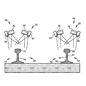
[0018] Referring initially to Figs. 1 and 2, a rail inspection apparatus
unit is
generally indicated by reference numeral 20. The rail inspection apparatus
includes a
carriage 22 for supporting test assemblies 24 mounted behind a test vehicle
26, a profiler
system 28 mounted under the test vehicle 26, and an encoder 30, all of which
are coupled
to a system controller 32 mounted inside the test vehicle 26.
100191 The test vehicle 26 includes front 34 and rear 36 rubber tires
and flanged
rail wheels 38 and 40. The flanged rail wheels 38 and 40 engage rails 42, 44
when the
test vehicle 26 is in a hi-rail configuration. In the hi-rail configuration
the front tires 34
are not in contact with the ground or rails 42 and 44, and the front of the
test vehicle 26 is
supported on the front flanged rail wheels 38. The rear tires 36 are in
contact with the
rails 42 and 44 to drive the test vehicle 26 along the rails 42 and 44. The
encoder 30 is
coupled to the front flanged rail wheels 38.
100201 The encoder 30 outputs information to the test assemblies 24 and
profiler system 28, which is used to determine position. The encoder 30 is
preferably a
linear encoder that outputs a digital signal corresponding to the rotation of
the flanged rail
WO 2013/028717 CA 02844113 2014-02-03
PCT/US2012/051789
-7-
wheel 38. The encoder 30 outputs a signal which corresponds to the rotation of
the rail
wheel 38, which in turn is used to calculate the position of the test vehicle
26.
[00211 Referring to Figs. 1 and 2, the profiler system 28 includes two
pairs of
laser transceivers 46 and 48, and may also include two pairs of line scan
cameras 50 and
52, each of which is directed at rails 42 and 44, respectively. The laser pair
46 includes a
gauge side laser transceiver 54 and a field side laser transceiver 56 directed
at rail 42.
Gauge side laser transceiver 54 scans the gauge side 58 of the rail 42,
including the web
and base, across the rail head 60. The field side laser transceiver 56 scans
the field side
62 of the rail 42, including the web and base, across the rail head 60.
Likewise, laser
transceiver pair 48 includes a gauge side laser transceiver 64 and a field
side laser
transceiver 66 directed at rail 44. Gauge side laser transceiver 64 scans the
gauge side 68
of the rail 44, including the web and base, across the rail head 70. The field
side laser
transceiver 66 scans the field side 72 of the rail 44, including the web and
base, across the
rail head 70. Each laser transceiver may scan at a fixed rate or frequency or
may be
triggered by the encoder 30 output. A laser profiling system such as a LMI
Gocator 2050
available from LMI Technologies may be used.
[0022] Line scan camera system 50 includes a gauge side line scan camera
76
and a field side line scan camera 78 directed at rail 42. The gauge side line
scan camera
76 captures a line or column of data of the gauge side 58 of the rail 42. The
field side line
scan camera 78 captures a line or column of data of the field side 62 of the
rail 42.
Likewise, the line scan camera system 52 include a gauge side line scan camera
80 and a
field side line scan camera 82 directed at rail 44. The gauge side line scan
camera 80
captures a line or column of data of the gauge side 68 of the rail 44 while
the field side
line scan camera 82 captures a line or column of the field side 72 of the rail
44. Line scan
cameras such as a Basler Runner series available from Basler Vision
Technologies may
be used.
[0023] Each of the line scan cameras 76, 78, 80 and 82 may be triggered
by the
encoder 30 output or scan at a set frequency such as 27,000 Hz, depending on
the
hardware selected and the storage capacity of the system. It should be
understood that
other frequencies and resolutions may be used for the line scan cameras and
laser
transceivers. Additionally, other image systems may be used such as a high
definition
video system, for example.
WO 2013/028717 CA 02844113 2014-02-03
PCT/US2012/051789
-8-
[0024] The pair of laser transceivers 46 and line scan cameras 50 may be
surrounded by a housing 84. Laser transceivers 48 and line scan cameras 52 may
be
surrounded by a housing 86. Each housing 84 and 86 encloses the laser
transceivers and
line scan cameras on the four vertical sides and top to protect the lasers and
cameras from
the environment, to improve the performance of the lasers and cameras in all
ambient
lighting conditions and to protect the eyes of any individuals working or
located around
the test vehicle 26.
[0025] Referring to Figs. 6-9, the carriage assembly 22 includes right
100 and
left 102 carriages. The right 100 and left carriages 102 are connected
together by a cross
member 104, which includes a pneumatic or hydraulic cylinder 106 to adjust the
width of
the carriage 22 as necessary to engage the rails 42 and 44. The left carriage
102 is a
mirror image of the right carriage 100 so only the right carriage will be
described in
detail, it being understood that the same detailed description applies to the
left carriage
102.
100261 The right carriage 100 includes a pair of flanged rail wheels
107, which
support the carriage 100 on the rail 42. The flanged rail wheels 107 are
mounted to a
frame 109, to which a first roller search unit (-RSU") assembly 108 and a
second RSU
assembly 110 is mounted. Nylon, Teflon or other high density polymer blocks
112 are
mounted between the flanged rail wheels 107 and the RSUs 108 and 110. Spray
nozzles
114 are mounted in the polymer blocks 112 and directed toward the running
surface of
the rail head 60 and the adjacent RSU 108 or 110. The polymer blocks 112
provide
protection for the RSUs 108 and 110. The spray nozzles 114 spray a liquid such
as water
or a water/ethylene glycol mixture on the running surface of the rail head 60
to remove
debris and to improve the contact of the RSUs 108 and 110 with the running
surface 69 of
the rail 42.
100271 RSU assembly 108 includes a tire 120 mounted on a wheel 122,
which
rotates with the tire 120 about an axle 124. The tire is clamped to the wheel
122 at its
bead 121 and includes a circumferential contact surface or tread 123, which
makes
contact with the running surface 69 of the rail head 60. The axle 124 is
mounted to the
frame 109. The tire 120 contains a coupling liquid 126 such as a
water/ethylene glycol
mixture. A transducer assembly 128 may be positioned within the tire 120 and
coupled to
the axle 124. The transducer assembly 128 includes a lower planar surface 129,
which is
WO 2013/028717 CA 02844113 2014-02-03
PCT/US2012/051789
-9-
mounted facing the circumferential contact surface 123 of the tire 120, and is
maintained
in a plane generally parallel to the running surface 69 of the rail head 60 at
a fixed
distance.
[0028] RSU assembly 110 includes a tire 130 mounted on a wheel 132,
which
rotates with the tire 130 about an axle 134. The axle 134 is mounted to the
frame 109.
The tire is clamped to the wheel 132 at its bead 131 and includes a
circumferential contact
surface or tread 133, which makes contact with the running surface 69 of the
rail head 60.
The tire 130 contains a coupling liquid 136 such as a water/ethylene glycol
mixture. A
transducer assembly 138 may be positioned within the tire 130 and coupled to
the axle
134. The transducer assembly 138 includes a lower planar surface 139, which is
mounted
facing the circumferential contact surface 133 of the tire 130, and is
maintained in a plane
generally parallel to the running surface 69 of the rail head 60 at a fixed
distance.
[0029] Referring to Figs. 9-13, the transducer assembly 128 includes a
transducer mount 140, which may be formed from a high strength plastic, epoxy,
resin,
Norylt resin blend of polyphenylene oxide and polystyrene ("PPO"),
polyphenylene
ether (-PPE") resin, or a PPE/olefin resin blend, for example.
[0030] Conventional ultrasonic transducers typically consist of a single
transducer that generates and receives ultrasonic sound waves, or a pair of
transducers,
one generating sound waves and the other receiving the echo returns. Phased
array
transducers typically include a transducer assembly with 8 to 256 individual
elements that
are individually controlled. The elements may be arranged in a strip (linear
array), a
square matrix (2-D array), a ring (annular array), a circular matrix (circular
array), or
other more complex shapes. The transducers typically operate at frequencies
from I MHz
to 10 MHz, for example.
100311 The ultrasonic phased array transducer system varies the time
between
the pulsing of individual elements of the array in such a way that the
individual waves
from each individual element combine in predictable ways to steer or shape the
beam
from the array. This is accomplished by selectively energizing or pulsing the
individual
elements at independent times. These respective delays are referred to as
delay laws
and/or focal laws. Based on the focal law of the array, the properties of the
transducer
assembly mount, the transmission medium and the geometry and acoustical
properties of
the test material, the beam can be dynamically steered through various angles
and focal
WO 2013/028717 CA 02844113 2014-02-03
PCT/US2012/051789
-10-
distances. Beam steering is accomplished in a fraction of a second allowing
the beam to
be steered to the optimal angle based on the orientation of the test material,
such as a rail
head, to scan from multiple angles, sweep over a range of angles, or scan at
multiple focal
depths. The ultrasonic phased array transducer can spatially sort a returning
wave front
according to the arrival time and amplitude at each element to be processed
and
displayed.
[0032] The transducer assembly 128 includes four ultrasonic phased array
transducers 142, 144, 146 and 148 secured to the mount 140 for generating
ultrasonic
acoustic beams forward and backward longitudinally generally parallel to a
longitudinal
axis X of the rail 42 and acoustic beams across the rail 42 at an angle
relative to the
longitudinal axis X from both the gauge side 58 and the field side 62 to
detect under shell
defects. The transducer assembly 128 also includes two ultrasonic phased array
transducers 150 and 152, secured to the mount 140, directed laterally or
transversely
relative to a lateral axis Y across the rail head 60 from both the gauge side
58 and field
side 62, to detect vertical split head (-VSH") defects.
[0033] The forward facing ultrasonic phased array transducers 142 and
146 are
mounted on the transducer mount 140 on a compound symmetric wedge shape
wherein
surface 154 is formed or cut at two different angles, for example, a wedge
angle 156 and
a roof angle 158. Wedge angle 156 may be between zero and 30 degrees and roof
angle
158 may be between 10 and 55 degrees, for example. The backward facing
ultrasonic
phased array transducers 144 and 148 are symmetrically secured to the
transducer mount
140 at the same angles as the corresponding forward facing ultrasonic phased
array
transducers 142 and 146. The laterally facing ultrasonic phased array
transducers 150 and
152 are secured to the transducer mount 140 at a roof angle of between about
10 and 55
degrees and a wedge angle of between about zero and 30 degrees, for example.
For
clarity, the ranges stated herein are stated as positive ranges, but it should
be understood
that a range includes a corresponding negative range or +/- a range.
[0034] In the exemplary embodiment, ultrasonic phased array transducers
142
and 146 are secured to transducer mount 140 such that beams 160 and 162, when
viewed
from above, are emitted parallel to rail 42 and when viewed in elevation view
are emitted
at an angle to produce a resultant beam in the rail 42 of about 60 to 80
degrees from
vertical. Likewise, ultrasonic phased array transducers 144 and 148 emit beams
164 and
WO 2013/028717 CA 02844113 2014-02-03
PCT/US2012/051789
-11-
166 parallel to rail 42 in the opposite direction from beams 160 and 162 when
viewed
from above, and at an angle to produce a resultant beam in the rail 42 of
about 60 to 80
degrees from a vertical axis Z when viewed in elevation.
[0035] Ultrasonic phased array transducers 142 and 146 also emit
ultrasonic
beams 168 and 170 directed generally parallel to rail 42 when viewed from
above, each
crossing the rail 42 in opposite directions at an angle to produce a resultant
beam in the
rail 42 of about 10 to 30 degrees. When viewed in elevation view, beams 168
and 170
descend into rail 42 at an angle to produce a resultant beam in the rail 42 of
about 60 to
80 degrees from vertical. Likewise, ultrasonic phased array transducers 144
and 148 also
emit beams 172 and 174 directed generally parallel to rail 42 when viewed from
above,
each crossing the rail 42 in opposite directions at an angle to produce a
resultant beam in
the rail 42 of about 10 to 30 degrees. When viewed in elevation view, beams
172 and 174
descend into rail 42 at an angle to produce a resultant beam in the rail 42 of
about 60 to
80 degrees from vertical. Ultrasonic beams 168, 170, 172 and 174 provides a
view of
under shell defects in the rail head 60 from both the gauge side 58 and the
field side 62.
[0036] Ultrasonic phased array transducers 150 and 152 emit ultrasonic
beams
176 and 178 which are directed downward at an angle to produce a resultant
beam in the
rail 42 of approximately 30 to 80 degrees to vertical when viewed in a
transverse
elevation view. Ultrasonic phased array transducers 150 and 152 may be
longitudinally
offset to avoid interference between the generated beams 176 and 178. Beam 176
enters
rail head 60 on the gauge side 58 and travels across head 60 to the field side
62. Beam
178 enters rail head 60 on the field side 62 and travels across head 60 to the
gauge side
58. Beams 176 and 178 detect vertical split head defects. Additionally,
ultrasonic phased
array transducers 150 and 152 may induce a shear beam, compression beam, or
both in
the head 60 depending on the rail head shape constraints.
[0037] Referring to Figs. 8 and 14-16, the transducer assembly 138
includes a
transducer mount 200 formed from a Noryl resin blend or other resin. The
transducer
assembly 138 may include individual ultrasonic transducers or one or more
ultrasonic
phased array transducers, directed at the rail 42. Preferably, transducer
assembly 138
includes a bank of forward-directed ultrasonic transducers 202 and rearward-
directed
ultrasonic transducers 204 mounted at an angle to produce a beam in the rail
of
approximately 30 to 60 degrees to vertical in opposite directions. As
illustrated, banks
WO 2013/028717 CA 02844113 2014-02-03
PCT/US2012/051789
-12-
202 and 204 each include four ultrasonic transducers 206, 208, 210, 212, 214,
216, 218,
220, although fewer or more ultrasonic transducers may be used. Each of the
ultrasonic
transducers 206-220 may be energized independently to emit a forward-directed
beam
222 and a rearward-directed beam 224. Beams 222 and 224 penetrate through the
web 61
of the rail 42 to the foot 63 to detect defects, such as web and bolt hole
cracks, weld
defects and centrally located transverse defects. The transducers selected to
fire are
determined by the rail geometry and known mount alignment, which applies to
each bank
of ultrasonic transducers.
[0038] The transducer assembly 138 may also include conventional
transducers
226 and 228, which may be mounted along a longitudinal centerline of
transducer mount
200 to produce a refracted sheer wave of about 55 to 85 degrees. The
transducers 226
and 228 may be energized to produce ultrasonic beams 230 and 232 at an angle
to
produce a resultant beam in the rail 42 of approximately 60 to 80 degrees
relative to
vertical axis Z in opposite directions generally parallel to longitudinal axis
X. Beams 230
and 232 detect transverse defects along the transverse axis Y of the rail head
60.
[0039] Transducer assembly 138 may include an additional ultrasonic
transducer bank 234 mounted at an angle of zero degrees to emit beam 236
substantially
vertically through the web 61 to the foot 63. Beam 236 detects defects such as
bolt-hole
cracks, centrally located defects as well as rail head 60 horizontal and
angled defects.
The ultrasonic transducers in bank 234 typically operate in pairs of adjacent
ultrasonic
transducers with one ultrasonic transducer emitting the beam 236 and the other
ultrasonic
transducer receiving the beam reflection. This pitch/catch combination reduces
false
returns from internal reflections within the RSU and reflections from the
surface of the
rail.
[0040] The pair of ultrasonic transducers in bank 234 is tightly spaced
and may
be transversely arranged as illustrated in Fig. 14 or may be longitudinally
arranged in a
stepped pattern as illustrated in Fig. 16.
[0041] To calculate the focal law for each ultrasonic phased array
transducer,
raw cross section points are determined by the laser transceivers 46 and 48.
For
simplicity and clarity, the process for one of the transverse pair 46 will be
discussed,
which will also apply to the other transceiver pair 48.
WO 2013/028717 CA 02844113 2014-02-03
PCT/US2012/051789
-13-
[0042] Referring to Figs. 2-5, data is received by each of the laser
transceivers
54 and 56, which are directed at rail 42. The data points are sent to the
system controller
32 along with the encoder data from encoder 30. Each set of data points from
the laser
transceivers represents a slice of the rail 42 at a given encoder count. The
system
controller 32 takes the raw data points from each laser transducers 54 and 56
for a given
encoder count and processes the points to produce a two-dimensional slice of
the rail 42
(see Fig. 4). From the two-dimensional slice, the system controller may
determine rail
features such as the head 60, web 61, foot 63, gauge surface of the head 65,
the field
surface of the head 67, the running surface 69, the gauge corner 71, the field
corner 73,
the gauge side web surface 75 and the field side web surface 77, for example,
as well as
the feature position and gauge of the rail. Additionally, extraneous material
layers such
as track structures (i.e. spikes, joint bars, etc.) and other layers such as
weeds, and debris
are identified and filtered out. Surface normals are calculated and smoothed
through
interpolation, averaging and plane segment reduction.
[0043] Based on the transducer assembly 128 and orientation of each
individual
ultrasonic transducer array, a range of steering angles is iteratively
calculated using ray
tracing techniques for each transducer array for each slice 74 of the rail 42,
or at a
predetermined interval based on time or travel.
[0044] For example, for a given ultrasonic transducer array, a trial
steering
angle is selected for an element within the array. The acoustic interface
collisions (time
and position) are calculated. Using Snell's law, the refraction or reflection
angles are
calculated at the interface for a known material, such as steel. The surface
normal and
acoustic velocities in the material are used to calculate the refraction
angle. This
calculation is repeated for all interfaces. Next, a target collision is
calculated and given a
score based on the target proximity and orientation. This process may be
repeated for all
angles and all elements of the transducer array. The target score determines
the selected
ray for a given element. Algorithms such as binary ray search may be used to
improve
processing time or improving the acoustic beam.
[0045] For each element of a given array, a total time travel to a
common target
point is calculated. The travel time for each element is compared to compute
the relative
delay in firing or energizing each element and receive digitizing delay to
steer the
resultant beam to the target point. For each profile slice of the rail, or at
a fixed time
WO 2013/028717 CA 02844113 2014-02-03
PCT/US2012/051789
-14-
interval, the focal laws are recalculated and compared to the focal laws for
the previous
profile slice of the rail. If the new focal laws are different than the
current applicable
focal law, the new focal law may be applied. The difference may be determined
on a
profile slice-by-profile slice basis, or for calculations falling outside a
tolerance or range
for the current applicable focal law. In this manner, the beam generated by
the ultrasonic
transducer array compensates for variations in the running surface 69 of the
rail and the
resultant effect on the angle of refraction.
[0046] For the transducer assembly 138, profile information is used to
determine which transducers to fire for any given profile slice. For example,
considering
transducer bank 202, the beam 222 generated by any of the transducers 206-212,
is
oriented to penetrate the web 61 of the rail 42 and travel to the foot 63. If
no return signal
is received, then no defect has been detected. However, in order for the beam
222 to
penetrate through the web 61 to the foot 63, the angle of incidence of the
beam 222
relative to the surface 69 of the rail head 60 generally should be in a
longitudinal plane
(Y-Z axes) perpendicular to the plane (X-Z axes) of the running surface 69 and
along the
centerline 81 of the web 61. If the running surface 69 is not in a horizontal
plane or the
web 61 is not oriented along the theoretical centerline of a new rail, the
beam 222 may
"miss" the web 61 and not penetrate to the foot 63.
[0047] To compensate for rail wear and variations prevalent in the field
with a
worn or damaged rail, profile data is used to determine which of the
transducers 206-212
will be fired for any given profile slice. Typically, transducers 208 or 210
will likely be
fired.
100481 Determination of which of the transducer pairs in the transducer
bank
204 and 234 is also based on profile information and calculation of the
incident angle
which will penetrate the web 61.
[0049] Referring to the Figs. 1-3, and 17-21, as the test vehicle 26
travels along
the rails 42 and 44, the laser profiling system 28 scans the rails 42 and 44
and the data is
output to the system controller 32. A 2-D profile 74 is generated for each
output from the
encoder 30 or at a predetermined frequency, and the geometry of each slice 74
is
determined. The geometry information is used by the system controller 32 to
dynamically calculate the optimal incident angle of a particular ultrasonic
beam with
respect to the rail head surface and steer the beam based on Huygen's
principle and the
W02013/028717 CA 02844113 2014-02-03
PCT/US2012/051789
-15-
focal laws. A steering angle for each transducer array may be calculated for
each slice 74
or periodically. The calculated steering angle may be dynamically applied for
each
profile or may be applied when a profile, which is out of range or tolerance
for a
particular steering angle, persists for two or more calculated profiles.
[0050] A focal law table is maintained by the system controller 32 and
stored
by encoder count. As the test vehicle travels down the rails which corresponds
to the
longitudinal or X-axis, the ultrasonic transducer system monitors the encoder
count and
selects the proper focal laws for each cycle. The ultrasonic transducer system
delays
firing of individual ultrasonic transducer elements within an array a given
amount based
on the applied focal law table, and delays receiving and sampling by the given
amount for
each element. The ultrasonic transducer system sums all element responses at
appropriate
time intervals and constructs an ASCAN per element group. The ASCAN is sent to
the
system controller 32 along with the encoder data.
[0051] The ASCAN data from the ultrasonic transducer system is placed in
3-D
by applying time along with the ray tracing calculated in the focal law
calculations. The
amplitude from the ASCAN may be represented in a number of ways such as color,
transparency, and/or disc size, for example. The ASCAN data based on the
encoder
location data is then represented along with the data from the profiler and
the image
constructed from the line scan cameras to optionally present a 3-D image of
the rail with
the location of a defect detected within the rail. Additionally, the 3-D image
may be
viewed by the operator from any angle, rotating the image as desired, and
overlaying
camera data to provide additional information to the operator.
[0052] When a relevant indication (defect) is detected, the area of the
defect
may be thoroughly inspected by taking advantage of the phased array's
capability to
sweep through a range of angles. This can be done in a single arc for a linear
arrangement of phased array elements or in multiple dimensions for a matrix or
other
arrangement of phased array elements. The system controller 32 calculates
focal laws to
do a targeted sweep of an area at a higher resolution to verify, size and
classify the defect.
Further, two or more arrays of transducers may be focused on a defect to scan
the defect
from various angles to provide additional information to better characterize
and display
the defect.
W020131028717 CA 02844113 2014-02-03
PCT/US2012/051789
-16-
[0053j The rail cross sections illustrated in Figs. 4 and 5 show a rail
profile for
an unworn rail 42 with orientation axes X (longitudinal), Y (transverse) and Z
(vertical).
The rail cross section illustrated in Fig. 18 shows a rail profile for an
unworn rail 400.
The rail cross sections illustrated in Figs. 17 and 19-21 show a rail profile
for a worn rail
402. Referring to Fig. 18, for the unworn rail 400, the incident angles of
beams 160 and
162 are dynamically adjusted by transducer arrays 142 and 146 respectively, to
produce
resultant beams 161 and 163.
[0054] Referring to Fig. 17, for the worn rail 402, the incident angle
of beam
160 is dynamically adjusted by transducer array 142 to produce resultant beam
161. The
incident angle of beam 162 is dynamically adjusted by transducer array 146 to
produce
resultant beam 163.
100551 Referring to Fig. 19, for the worn rail 402, the incident angle
of beam
168 is dynamically adjusted by transducer array 142 to produce resultant beam
169. The
incident angle of beam 170 is dynamically adjusted by transducer array 146 to
produce
resultant beam 171. Because of the worn rail head 406 on the gauge side 408 of
the rail
head 406 the angle of incident (the primary steering angle) is adjusted by
steering the
beam to achieve the desired angle of refraction in the rail head 406.
100561 If a defect 410 or 412 for example, is detected, information such
as the
characteristics of the defect, location, image information at the location of
defect, and
geometry of the defect may be stored. Additionally, the system controller 32
may direct
one or more phased array transducers in the second or additional trailing RSUs
to scan or
sweep the area of a defect detected by the first RSU 108 to obtain additional
information
regarding the defect. The defect location in the head, or anywhere a defect is
located,
may be displayed graphically along with the profile and line scan camera data
to provide
the operator with a 3-D image that may be manipulated, rotated and viewed from
any
orientation or angle. The defect may be viewed from any vantage point outside
the rail or
may be viewed from within the rail. The size of the defect 410 or 412, for
example, may
be represented by concentric rings around the defect or by colors to provide
additional
information to the operator.
[0057] It is to be understood that while certain now preferred forms of
this
invention have been illustrated and described, it is not limited thereto
except insofar as such
limitations are included in the following claims.