Note: Descriptions are shown in the official language in which they were submitted.
CA 02844287 2014-02-05
WO 2012/021667 PCT/US2011/047342
KINETIC ENERGY MANAGEMENT SYSTEM
CROSS-REFERENCE TO RELATED APPLICATIONS
[0001] This application is related to and claims priority to U.S.
Provisional Patent
Application Serial Number 61/372,766 filed on August 11, 2010, bearing the
title "Kinetic
Energy Management System". All disclosures in this prior application are
incorporated by
reference herein.
TECHNICAL FIELD
[0002] This disclosure is related generally to energy management systems
capable of
managing kinetic energy in the form of vibrating mechanical input. In
particular, this
disclosure is directed to energy management systems for absorbing transverse
shock or
vibration experienced by a moving vehicle.
BRIEF SUMMARY
[0003] A kinetic energy management system is disclosed for managing
vibration
experienced by a moving vehicle, where the vibration occurs in a direction
generally
transverse to the direction of movement of the vehicle.
[0004] One exemplary kinetic energy management system includes an
electromechanical shock absorber device comprising a first main body movably
attached to a
second main body for reciprocal movement therebetween, the first main body
having a
winding or coil movable therewith and the second main body having a magnet
movable
therewith. The magnet may be movable relative to the winding by the reciprocal
relative
movement of the first and second main bodies such as to generate a current in
the winding.
One of the first or second main bodies is adapted for engagement with a
vehicular component
that experiences the irregularities of a surface on which the vehicle travels
and the other of
the main bodies is adapted for engagement with a load bearing portion of the
vehicle for
which isolation from the vibrations due to irregularities of the surface is
desired. The
interaction of the magnet and the winding may be used to translate between
reciprocating
kinetic energy associated with the motion of the vehicle over the surface
irregularities and
electrical energy associated with current through the winding. The vehicle may
be a car or
1
CA 02844287 2014-02-05
WO 2012/021667 PCT/US2011/047342
truck and the surface may be a road. Alternatively, the vehicle may be a boat
and the surface
may be the surface of a body of water.
[0005] Another exemplary kinetic energy management system includes an
electromagnetic shock absorber having at least two nested magnetic components,
such as
toroidal magnetic components, one active component creating a magnetic field
and one
passive component from which the energy of the field is converted to
mechanical energy, or
visa versa, through relative movement between the active and passive
component. The
passive component may be a magnetic piston and the active component may be a
coiled
electrical winding. For conversion of kinetic energy into electrical energy,
external forces,
originating from surface irregularities as a vehicle travels in a forward
direction, cause
relative movement between the magnetic components resulting in current flowing
through the
active component.
[0006] In another electromechanical shock absorber, a winding or coil
defines a
longitudinal axis. Two fixed magnets, one disposed at each end of the
longitudinal axis, act
on a magnetic piston movably disposed relative to the winding and displaceable
along the
longitudinal axis. The relative motion between the piston and the winding may
be horizontal
or vertical or at any angle therebetween.
[0007] In still another exemplary system, the electromechanical shock
absorber has
an elongated channel defined by a radial magnetic source, a winding disposed
coaxial with
the radial magnetic source, two oppositely disposed axial magnets in fixed
locations at
opposing ends of the elongated channel and a piston disposed therebetween. The
radial axial
magnets may be rare earth magnets such as neodymium magnets.
[0008] The energy management system may be used to passively absorb a
portion of
the transverse vibration by surface irregularities as well as to provide
electrical energy for
later use by passively converting the kinetic energy to electricity.
Alternatively, the energy
management system may be used to actively manage the amplitude or the
frequency of the
transverse vibrations experienced by the load-bearing portion of the vehicle
by selective
application of a current to the windings. The energy management system may
therefore
include an electronic control system to control the application of current to
the winding as
well as to regulate the use of current generated in the winding by the
movement of the
magnet.
2
CA 02844287 2014-02-05
WO 2012/021667 PCT/US2011/047342
[0009] The first and second main bodies of the electromagnetic shock
absorber may
create an enclosure or housing for the magnet, the winding, electronic
controls, shock-
absorbing components, and a spring. The main body may be constructed to have a
similar
shape and mounting function as a conventional mechanical shock absorber or may
have
alternate shapes and features for special applications.
[0010] The magnet may be a disc shaped compound complex radial magnetic
piston
manufactured or selected to effectively present axial poles of opposing
polarity on its
respective faces as well as to effectively present a radial pole of a single
polarity.
[0011] In still another exemplary device, the piston may be a complex
magnet having
an axial magnetic component responsive to the oppositely disposed axial
magnets, and a
radial magnetic component responsive to the radial magnetic source to
generally maintain the
piston in a floating position within an elongated channel defined by the
winding or coil. The
opposing magnetic fields of the oppositely disposed axial magnets confine the
floating piston
within the channel and increase the number and speed of the oscillations. A
cylinder may be
provided defining the channel and may be wrapped tightly with a toroidal
copper winding
defining the winding. As the piston passes through the winding, its movement
creates a
moving magnetic field that is converted into electrical current flowing
through the winding.
[0012] Additional magnets may be configured around the cylinder allowing
the piston
to float freely, reducing friction between the piston and the walls of the
cylinder.
[0013] The energy management system may be used in parallel or in series
with a
mechanical energy managing system such as a mechanical shock absorber or a
mechanical
spring. Alternatively, a mechanical energy managing system may be integrated
into a shock-
absorbing device of the type disclosed herein.
[0014] In one exemplary energy management system disclosed, the vehicle
using an
electromagnetic shock absorber is a car or truck and the surface is a road.
The
electromagnetic shock absorber is installed in parallel with a conventional
mechanical shock
absorber or spring. Alternatively, the electromechanical shock absorber
incorporates
mechanical shock absorbing components and is substituted for a conventional
mechanical
shock absorber. Alternatively, the electromechanical shock absorber
incorporates a spring
and is substituted for a conventional mechanical spring.
3
CA 02844287 2014-02-05
WO 2012/021667 PCT/US2011/047342
[0015] In another exemplary embodiment, the vehicle is a boat and the
surface is the
surface of a body of water. An electromechanical shock absorber may be
installed between
the hull of the boat and a pontoon floating on the surface of the water
adjacent the hull. A
plurality of electromechanical shock absorbers may be provided adjacent each
side of the
boat coupled to one or more pontoons on each side of the boat. The action of
waves will
displace the magnet relative to the windings of the electromechanical shock
absorbers to
induce current in the windings to generate electrical power or to provide a
damping effect on
the motion of the boat in response to the waves. The windings of the
electromechanical
shock absorbers may also be selectively powered to raise the pontoons above
the water
surface when desired.
BRIEF DESCRIPTION OF THE DRAWINGS
[0016] Some configurations of the energy management system will now be
described,
by way of example only and without disclaimer of other configurations, with
reference to the
accompanying drawings, in which:
[0017] Figure 1 is a schematic view of a prior art automotive shock
absorbing system
including conventional mechanical shock absorbers;
[0018] Figure 2 is a schematic view of a conventional mechanical shock
absorber
illustrating the operation thereof, with its internal components in an
extended operational
configuration;
[0019] Figure 3 is a schematic view of the shock absorber of Figure 3
with its
internal components in an compressed operational configuration;
[0020] Figure 4 is a schematic perspective view of a conventional shock
absorber
mounted in parallel with an exemplary electromagnetic shock absorber;
[0021] Figure 5 is a schematic perspective view of a conventional shock
absorber
mounted in parallel with an alternative exemplary electromagnetic shock
absorber;
[0022] Figure 6 is a schematic perspective view of another alternative
exemplary
electromechanical shock absorber which may be substituted for a conventional
mechanical
shock absorber;
4
CA 02844287 2014-02-05
WO 2012/021667 PCT/US2011/047342
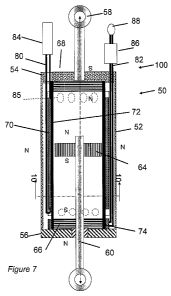
[0023] Figure 7 is a sectional view of the electromagnetic shock absorber
of Figure 4
taken along line 7-7 thereof;
[0024] Figure 8 is a partial sectional view of the electromagnetic shock
absorber of
Figures 4 and 7 taken along line 8-8 of Figure 7;
[0025] Figure 9 is an exploded schematic view of certain internal
components of the
electromagnetic shock absorber of Figures 57 and 9;
[0026] Figure 10 is an exploded schematic view similar to Figure 9 but
illustrating an
alternative exemplary electromagnetic shock absorber;
[0027] Figure 11 is a sectional view similar to Figure 7, but
illustrating another
alternative exemplary electromagnetic shock absorber with control components
incorporated
into its housing;
[0028] Figure 12 is a sectional view similar to Figure 7, but
illustrating still another
alternative exemplary electromagnetic shock absorber with damping components
incorporated into its housing;
[0029] Figure 13 is a sectional view similar to Figure 7, but
illustrating yet another
alternative exemplary electromagnetic shock absorber with damping components
and a spring
incorporated into its housing;
[0030] Figure 14 is a perspective view of an exemplary linear kinetic
energy
management system including an electromechanical shock absorber for use in
association
with a boat;
[0031] Figure 15 is a perspective view of an alternate exemplary kinetic
energy
management system including a plurality of electromechanical shock absorbers
for use in
association with a boat;
[0032] Figure 16 is a side elevational view of the kinetic energy
management system
of Figure 15;
[0033] Figure 17 is a top plan view of the kinetic energy management
system of
Figures 15 and 16;
CA 02844287 2014-02-05
WO 2012/021667 PCT/US2011/047342
[0034] Figure 18 is a front elevational view of the kinetic energy
management system
of Figures 15-17, illustrating the kinetic energy management system mounted to
the side of a
boat; and
[0035] Figure 19 is a sectional view through yet another kinetic energy
management
system having an electromagnetic shock absorber incorporated into a float.
DETAILED DESCRIPTION OF THE DISCLOSURE
[0036] Referring now to the drawings, exemplary energy management systems
are
shown in detail. Although the drawings represent alternative configurations of
energy
management systems, the drawings are not necessarily to scale and certain
features may be
exaggerated to provide a better illustration and explanation of a
configuration. The
configurations set forth herein are not intended to be exhaustive or to
otherwise limit the
device to the precise forms disclosed in the following detailed description.
[0037] Referring now to the drawings, Figure 1 schematically illustrates
an example
of a prior art automotive energy management system 12 using conventional
mechanical shock
absorbers 10 to isolate the load bearing portion of a vehicle, such as a
passenger
compartment, from the vibrations of the wheel and axle system experienced as
the vehicle
moves in a forward direction over an uneven road surface. As shown in Figure
1, prior art
energy management systems 12 may include a spring 14, such as a coil spring or
a leaf
spring, to further manage the vibration between suspension components 16 and
18.
[0038] Figures 2 and 3 schematically illustrate a conventional mechanical
shock
absorber 10 with its internal components in an extended and compressed
configuration,
respectively. As illustrated, a conventional mechanical shock absorber 10
typically has a rod
11 having a piston 13 on its extreme end reciprocally mounted in a cylinder 15
such that
piston 13 sealingly engages an inner wall of cylinder 15. A seal 17 is also
provided between
the free end of rod 11 and an end 25 of cylinder 15 receiving rod 11. A
floating piston 19
divides cylinder 15 into an oil reservoir 21, in which piston 13 is free to
oscillate along the
longitudinal axis of cylinder 15, and an air chamber 23 disposed remote from
piston 13. As
seen by comparing Figure 2 and Figure 3, the oil in oil reservoir 21 resists
the motion of
piston 15 in response to vibration input to shock absorber 10, thereby
absorbing some of the
6
CA 02844287 2014-02-05
WO 2012/021667 PCT/US2011/047342
kinetic energy in the vibration. Floating piston 19 is free to move in
response to the
compression of oil in oil reservoir 21 as piston 13 is moved by rod 11.
[0039] Referring to Figure 4, an electromagnetic shock absorber 50 may be
placed in
mechanical parallel with conventional mechanical shock absorber 10 to convert
a portion of
the kinetic energy of vibrations experienced by the shock absorbers 10 and 50
into electrical
energy. As shown in Figure 4, electromagnetic shock absorber 50 may be
configured to be of
the same length and diameter as conventional mechanical shock absorber 10 and
may be
extended between the same components as conventional mechanical shock absorber
10 in
adjacent mounting locations. Alternatively, as shown in Figure 5,
electromagnetic shock
absorber 50' may be configured differently than conventional mechanical shock
absorber 10
and may be extended between different components of a suspension system or at
mounting
points experiencing a different amount of displacement than conventional
mechanical shock
absorber 10. For some applications in particular, it may be desirable to
intentionally use a
leveraging system so that electromagnetic shock absorber 50' and conventional
mechanical
shock absorber 10 experience different force levels in response to vibration
to optimize their
load absorbing or electrical energy generating characteristics.
[0040] Alternatively, as shown in Figure 6 an electromagnetic shock
absorber 50"
may be manufactured to the same dimensions as a conventional mechanical shock
absorber
and have shock absorbing components incorporated therein, as described in
detail later
herein. Electromechanical shock absorber 50" may therefore be substituted for
a
conventional mechanical shock absorber in a suspension system since it offers
the
functionality of both types of shock absorbers.
[0041] Referring now generally to Figures 7-13 various exemplary
electromagnetic
shock absorbers 50, 50', 50" and 50a are illustrated and the general
arrangement of the
mechanical, magnetic and electromagnetic components of energy management
system 100
will be described.
[0042] Referring generally to Figures 7-9, schematically illustrating a
generalized
electromechanical shock absorber 50, and more particularly to Figure 7,
illustrating a section
through shock absorber 50, the arrangement of the magnetic and electromagnetic
components
will be described. In particular, electromechanical shock absorber 50 includes
a cylinder 52
having an upper end wall 54 and a lower end wall 56. A first rod 58 is fixed
to the upper end
7
CA 02844287 2014-02-05
WO 2012/021667 PCT/US2011/047342
54 connectable to a first suitable mounting point on a suspension system. A
second rod 60,
connectable to second suitable mounting point of a suspension system, is
inserted through an
aperture in the lower end wall 56 and is reciprocal relative to cylinder 52.
[0043] A magnetic piston 64 is mounted to rod 60 within cylinder 52 and
is
constrained to oscillate within cylinder 52 in response to relative movement
between the first
and second mounting points of the suspension system. Magnetic piston 64 may be
press
fitted to rod 60 or secured thereto by other means, such as clips. Magnetic
piston 64 may be
a complex magnet having an axial magnetic component and a radial magnetic
component, as
illustrated and described in related US patent application serial number
61/171,641 and PCT
patent application serial number PCT/US10/32,037 described above and
incorporated by
reference herein.
[0044] An optional pair of axial magnets 66 and 68 may be disposed within
cylinder
52 adjacent walls 54 and 56. Magnets 66 and 68 and magnetic piston 64 are
oriented to
present faces to each other of opposite polarity. Magnets 68 and 66 may be
used to assist in
the orientation of magnet piston 64 and to manage the oscillatory motion of
magnet piston 64.
[0045] A winding, such as a toroidal winding 70, is provided within
cylinder 52,
which may be protected from magnetic piston 70 by a cylindrical wall 72.
Magnetic piston
64 extends nearly to wall 72. For some applications, it may be desirable for
magnetic piston
64 to form a sliding seal with wall 72. It will be appreciated that
oscillatory motion of
magnetic piston 64 within cylinder 52 will cause a current to flow in toroidal
winding 70,
thus permitting the winding to convert the kinetic energy of vibrations in the
suspension
system to electrical energy which may be used by the vehicle. Conversely,
driving a current
through toroidal winding 70 will impart a force on a magnetic piston 64,
causing relative
motion between rods 58 and 60, which may in turn deliver a force to the
components of the
suspension system to manage the oscillatory motion there between.
[0046] Electromechanical shock absorber 50 optionally includes another
toroidal
winding 74 disposed adjacent axial magnet 66. Toroidal winding 74 may also be
selectively
energized to temporarily exert a force on magnetic piston 64 to initiate or
assist the
oscillation of magnetic piston 64. Wires 80 and 82 connected respectively to
toroidal
winding 70 and 74 extend from cylinder 52 to an external load 84 for the use
of the current
8
CA 02844287 2014-02-05
WO 2012/021667 PCT/US2011/047342
generated in winding 70 and connect toroidal windings 72 and 74 to an external
source of
power 86 and controller 88 for selectively powering the windings.
[0047] Cylinder 52 may be provided with apertures 85 for admission of air
to cool the
internal components and to regulate the buildup of air pressure on opposing
sides of magnetic
piston 64.
[0048] Electromechanical shock absorber 50 may be configured to provide
either
alternating current or direct current output. Electrical load 84 may be one or
more electrical
devices capable of consuming the power, one or more storage devices used to
store power for
later use, or a power distribution system. Exemplary storage devices for
electrical load 84
may include the vehicle main battery or a local battery for use by controller
88 and may
therefore be the same component as power source 86.
[0049] While power source 86, controller 88, and electrical load 84 are
schematically
illustrated as independent of electromechanical shock absorber 50, either or
both may be
integrated with an electromechanical shock absorber 50a of Figures 6 and 11,
as best shown
in Figure 11 and described below. In particular, one or both may alternatively
be affixed to a
cover 90 mounted over one end of cylinder 52.
[0050] Figure 10 schematically illustrates an alternative
electromechanical shock
absorber 50b, in which the arrangement of the magnetic and electromagnetic
components is
similar to those described above, except that piston 64a and axial magnets 66a
and 68a are
ring- shaped. In this arrangement, piston 64a is disposed outside of the
toroidal winding 70a.
Magnetic piston 64a interacts with axial magnets 68a and 66a and toroidal
winding 70a
according to the same principles as the similarly numbered components of the
electromechanical shock absorber 50 of Figures 7 and 8 described above.
[0051] Still other configurations are possible. For example, Figure 12
schematically
illustrates an alternative electromechanical shock absorber 50', in which a
mechanical
vibration absorbing system has been included. In particular, a fluid
compartment 90
surrounded by wall 72' resiliently flexes and absorbs some vibration in
response to the
pressure caused by the movement of piston 64'. Figure 13 schematically
illustrates another
alternative electromechanical shock absorber 50", in which a mechanical
vibration absorbing
system and a spring 94 has been included. In particular, a floating piston 92
engages wall
9
CA 02844287 2014-02-05
WO 2012/021667 PCT/US2011/047342
72" and is displaceable in response to the pressure caused by the movement of
piston 64" to
absorb some vibration between rods 58" and 60". A spring 94 wound around the
outside of
cylinder 52" and connected to rods 58" and 60" is provided in mechanical
parallel
arrangement with shock absorber 50".
[0052] It
should be noted that a plurality of toroidal windings may be provided. One
or more passive toroidal windings may be provided to create an output current
as a function
of the motion of piston 64, 64' or 64a. One or more active toroidal windings
may also be
provided to create a magnetic field opposing the magnetic field of piston 64,
64' or 64" for
selectively driving the piston when active oscillation management is desired.
The passive
toroidal winding may be significantly larger than the active toroidal winding.
As described
above, the energy created by piston 64, 64' or 64a interacting with a passive
toroidal winding
may be transferred to and stored in an electrical storage device 84, such as a
battery or
capacitor. An active toroidal winding may use the electrical energy previously
created by the
moving piston magnets interacting with the passive toroidal winding and
subsequently stored
in electrical storage device 84. The toroidal windings may be wound about and
supported by
wall 72 or by a tube formed of a suitable non-conductive material such as
plastic.
[0053] It
will be appreciated that electromechanical shock absorbers 50, 50' and 50"
may be used in other applications, such as non-vehicular applications, as a
generator, a motor,
a pump, a compressor, an engine, or an electrical power transformer. When used
as a
transformer, electrical power may be input to passive toroidal windings and
electrical power
may be output from active toroidal windings. When used as a generator,
mechanical power
may be input by reciprocally moving the rods relative to each other and
electrical power may
be output from a passive toroidal winding. The output of the energy conversion
device can
be configured to be direct or alternating current. The mechanical motion may
be provided,
for example, by any source that is capable of oscillating the shock absorber
along its
longitudinal axis. Alternatively, mechanical motion may be imparted to the
magnetic piston
by application of a current to an active winding. The mechanical motion may be
used to
drive a compressor or a pump. Alternatively, a compressor or pump may be
incorporated
into the shock absorber. For example, the magnetic piston may sealingly engage
the sides of
the cylindrical wall and the two ends of the housing may have openings, to
allow the
movement of air or a fluid pumped by the movement of the piston.
CA 02844287 2014-02-05
WO 2012/021667 PCT/US2011/047342
[0054] An electromechanical shock absorber may be configured as a single
stage
having a single set of axial magnets, a single set of toroidal windings, and a
single piston as
described above. Alternatively, a device may have multiple stages, each with
at least its own
piston, which may operate in series, in parallel, or independently. When
constructed with
multiple stages, the individual stages may share components, such as outer or
inner housings.
Alternatively, multiple energy conversion devices may be connected
electrically or
mechanically in parallel or in series.
[0055] For active implementation, a control algorithm may be provided
capable of
analyzing the vibration characteristics of the surface and applying a current
to the winding to
provide piston deceleration and acceleration to tune the response of the shock
absorber 50 to
the terrain. The system may be designed to self-adjust to changing road
conditions.
[0056] Referring now generally to Figures 14-19 various exemplary marine
versions
of a kinetic energy management system 100 similar one of the kinetic energy
management
systems described above are illustrated and the general arrangement of the
mechanical,
magnetic and electromagnetic components of kinetic energy management system
100 will be
described.
[0057] Referring to Figure 14, an exemplary kinetic energy management
system 100
using a single electromagnetic shock absorber 50 is illustrated for attachment
to a boat.
Shock absorber 50 may be any of the exemplary shock absorbers described above.
Kinetic
energy management System 100 includes a frame structure including a shaft 102
having two
or more wheels 104 for rolling engagement with the side of a boat, not shown
in Figure 14.
A frame member 106 is secured parallel to shaft 102 by two or more cross
members 108
extending between shaft 102 and frame member 106. Frame member 106 is attached
to a top
of a float, such as a pontoon 110. An electromagnetic shock absorber 50 is
connected at one
end to Frame member 106 and extends upwardly there from for interconnection
with the side
of a boat, not shown in Figure 14.
[0058] Referring to Figures 15-18, an exemplary kinetic energy management
system
100a using a multiple electromagnetic shock absorbers 50 is illustrated for
attachment to a
boat 112 (see Figures 17 and 18). Kinetic energy management systems 100 may be
attached
to a boat 112 in a manner similar to that described for kinetic energy
management systems
100a. The components of kinetic energy management system 100a include shaft
102, wheels
11
CA 02844287 2014-02-05
WO 2012/021667 PCT/US2011/047342
104, frame member 106, cross members 108 and pontoon 110, similar in form and
function to
those described above for kinetic energy management system 100, except that a
plurality of
electromagnetic shock absorbers 50 are each connected at one end to frame
member 106 and
extends upwardly there from for interconnection with the side of boat 112.
[0059] The upper end of each shock absorber 50 may be connected to the
side of boat
110 by a spherical rod joint 116, as shown in Figure 18, or an equivalent
structure. Shaft 102
may be similarly attached to the side of boat 112 by a spherical rod joint or
an equivalent
structure. An elastomeric travel limiter or jounce stop 114 may be provided at
the upper end
of each shock absorber 50, as shown in Figure 18, and designed to maintain
torques within
limits to avoid bending of components. Cross members 108 may be pivotally
attached to
frame member 106 so that shaft 102 and cross members 108 form a pivoting
control arm for
controlling the placement of pontoon 110 relative to side of boat 112. If
desired, a third
frame portion disposed at an angle above the pivoting control arm may be
provided for
additional securement to boat 112. Cross members 108 may be adjustable in
length to
accommodate differently shaped boats. Exemplary kinetic energy management
system 100a
may be installed so that shock absorbers 50 are generally perpendicular to the
water, with the
spherical rod joint assisting in fore-aft compliance.
[0060] Boat 112 may be provided with one or more kinetic energy
management
systems 100 or 100a on each side of the boat. It will be appreciated that the
kinetic energy
management systems 100 or 100a on each side of the boat may generate
electricity from
wave action whether boat 112 is in motion or is resting at anchor or at a
dock. Kinetic energy
management systems 100 and 100a also limit fore-aft motion of boat 112 (pitch)
and side-to-
side motion (roll) to provide stability to boat 112 due to the shape of
pontoon 110. In
particular, long properly designed pontoons function as outriggers while
minimizing drag.
One or more windings in shock absorbers 50 may be selectively powered to
contract the
shock absorbers and thereby raise the pontoon 110 from the water when desired.
[0061] Figure 19 illustrates yet another configuration for a kinetic
energy
management system wherein a cylinder 52b of a shock absorber 50b is fitted
into a cavity 118
in a float 110and affixed therein.
[0062] The above disclosure therefore provides a kinetic energy
management system,
the kinetic energy management system having a magnetic piston displaceable
along a first
12
CA 02844287 2014-02-05
WO 2012/021667 PCT/US2011/047342
longitudinal axis and a winding disposed about the first longitudinal axis to
cyclically interact
with the magnetic piston to induce an electrical current and voltage in the
winding, thereby
creating electrical energy. The system may have a plurality of said windings
and plurality of
magnetic pistons, each of said magnetic pistons cyclically imparting a
magnetic field across
one of said windings to contribute to the generation of electrical energy. The
kinetic energy
management system may have one of said magnet or said winding interconnected
with a
floatation component adapted for floating on the surface of a body of water
and the other of
and said magnet or winding interconnected with a boat whereby said kinetic
energy
management system may be used to manage the transverse vibration of the boat
as it moves
across the surface of the body of water. The flotation component may be a
pontoon.
Multiple shock absorbers may be mounted between the side of a boat and a
pontoon. One or
more kinetic management systems including a pontoon and a plurality of shock
absorbers
may be mounted on each side of a boat. The pontoons may be selectively raised
from the
water depending on conditions.
[0063]
Features shown or described in association with one configuration may be added
to or used alternatively in another configuration, including configurations
described or
illustrated in the provisional patent applications and the patent cooperation
treaty patent
application referred to in the above cross-reference to related applications.
The scope of the
device should be determined, not with reference to the above description, but
should instead
be determined with reference to the appended claims, along with the full scope
of equivalents
to which such claims are entitled. It is anticipated and intended that future
developments will
occur in the arts discussed herein, and that the disclosed systems and methods
will be
incorporated into such future configurations. In sum, it should be understood
that the device
is capable of modification and variation and is limited only by the following
claims.
[0064] All
terms are intended to be given their broadest reasonable constructions and
their ordinary meanings as understood by those skilled in the art unless an
explicit indication
to the contrary in made herein. In particular, use of the singular articles
such as "a" and
"the," should be read to recite one or more of the indicated elements unless a
claim recites an
explicit limitation to the contrary.
[0065] In
one exemplary embodiment, a kinetic energy management system includes
a shock absorber device comprising a first main body movably attached to a
second main
13
CA 02844287 2014-02-05
WO 2012/021667 PCT/US2011/047342
body for reciprocal movement there between, the first main body having a coil
depending
therefrom and the second main body having a magnet depending therefrom. The
magnet may
be movable relative to the coil by the reciprocal relative movement of the
first and second
main bodies such as to generate a current in the coil. One of the first or
second main bodies
is adapted for engaging with a vehicular component that experiences the
irregularities of the
surface on which the vehicle travels and the other of the main bodies is
adapted for engaging
a load-bearing portion of the vehicle for which isolation from the
irregularities of the surface
is desired. The interaction of the magnet and the coil may be used to
translate between
reciprocating kinetic energy associated with the motion of the vehicle over
the surface
irregularities and electrical energy associated with current through the coil.
14