Note: Descriptions are shown in the official language in which they were submitted.
CA 02844971 2014-03-06
FIBER OPTIC CABLE STRENGTH MEMBER BRACKET
TECHNICAL FIELD
The present invention generally relates to optical communications equipment,
and particularly
relates to techniques for terminating fiber optic cables at a subscriber
termination point.
BACKGROUND
Today's communication networks provide transport of voice, video and data to
both residential
and commercial customers, with more and more of those customers being
connected by fiber
optic cables. In these communication networks, information is transmitted from
one location to
another by sending pulses of light through the fiber optic cables. Fiber optic
transmission
provides several advantages over electrical transmission techniques, such as
increased bandwidth
and lower losses.
Fiber optic cables typically include a number of individual optical fibers
surrounded by a cable
jacket. The individual optical fibers act as a light waveguide between two
ends of the cable. The
individual optical fibers are susceptible to damage. Cable jackets provide a
durable exterior
around the optical fibers. Environmental conditions, such as changes in
temperature, may cause
expansion and contraction of cable polymers within the cable jacket. Cable
jackets alone do not
necessarily provide adequate protection of the optical fibers from forces that
pull or push on the
cable polymers.
1 of 24
CA 02844971 2014-03-06
Some modern fiber optic cables additionally include one or more strength
members located
inside the cable jacket. A strength member is non-data transmitting component
of a fiber optic
cable that provides desired structural characteristics to the fiber optic
cable. For instance,
strength members prevent optical fibers from being damaged due to tensile and
compressive
forces exerted on the fiber optic cable. In addition, strength members may
provide desired
separation between the optical fibers.
Fiber optic cables are connected to a desired location at a termination point.
To make a working
connection, the installer must first expose bare optical fibers by removing
the cable jacket,
optical fibers and other elements of the cable. The fibers are then spliced to
terminal equipment.
If a fiber optic cable that includes a strength member or strength members is
used, the ends of the
strength member must be exposed from the cable jacket. Exposed ends of
strength members are
problematic during an installation because the ends of the strength member may
cause damage to
the optical fibers.
SUMMARY
Embodiments disclosed herein relate to a strength member used for securing one
or more
exposed ends of strength members to a termination point where a splice of
fiber optic cables may
be effectuated. Advantageously, the strength member bracket helps reduce cable
expansion and
contraction at cut ends of a cable jacket by coupling the cable jacket and
strength member(s) to a
termination point. Additionally, the strength member bracket secures the end
of strength
member(s) away from exposed optical fibers and protects the exposed optical
fibers from the
strength member(s).
2 of 24
CA 02844971 2014-03-06
In one embodiment, a bracket for securing an end of a fiber optic cable,
having at least one
strength member, to a termination point is provided. The bracket includes a
base portion at a
first end of the bracket, a retention feature at a second end of the bracket
opposite to the first end
that is adapted to receive and at least partially surround an exposed end of
the at least one
strength member, and an elongated portion extending from the base portion to
the retention
feature. The bracket further includes a first flat surface, on the base
portion or the elongated
portion, having at least one opening adapted to receive a fastener for
mounting the strength
member bracket to a first mounting surface on the termination point. The
bracket further includes
a first flange, disposed along the elongated portion that is adapted to
receive a tether for securing
a jacketed portion of the fiber optic cable to the bracket.
In another embodiment, an assembly for securing an end of a fiber optic cable
to a termination
point is provided. The assembly includes a fiber optic cable having at least
one strength member,
optical fibers, and a cable jacket, wherein an end of the at least one
strength member and ends of
the optical fibers are exposed from the cable jacket. The assembly further
includes a tether and a
strength member bracket. The strength member bracket includes a retention
feature at a first end
of the bracket receiving and at least partially surrounding the exposed end of
the at least one
strength member, a base portion at a second end of the bracket that is
opposite to the first end,
and an elongated portion extending from the base portion to the retention
feature. The strength
member bracket further includes a first flat surface, on the base portion or
the elongated portion,
having at least one opening adapted to receive a fastener for mounting the
strength member
bracket to a first mounting surface on the termination point. The strength
member bracket further
3 of 24
CA 02844971 2014-03-06
includes a first flange receiving the tether, wherein the tether secures a
jacketed portion of the
fiber optic cable against the first flange, thus securing the fiber optic
cable to the strength
member bracket.
Of course, the present invention is not limited to the above features and
advantages. Indeed,
those skilled in the art will recognize additional features and advantages
upon reading the
following detailed description, and upon viewing the accompanying drawings.
BRIEF DESCRIPTION OF THE DRAWINGS
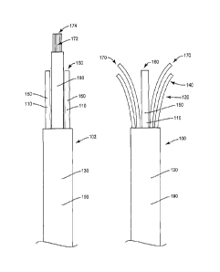
Fig. 1 illustrates the exposed ends of exemplary fiber optic cables having at
least one strength
member.
Fig. 2 illustrates an exemplary termination point for a fiber optic cable.
Fig. 3 illustrates a front perspective of an exemplary strength member bracket
and components
used to affix a fiber optic cable having a strength member to the strength
member bracket.
Fig. 4 illustrates a rear perspective of an exemplary strength member bracket.
Fig. 5 illustrates an exemplary assembly for securing an end of a fiber optic
cable having one
strength member to a termination point.
Fig. 6 illustrates an exemplary assembly for securing an end of a fiber optic
cable having two
strength members to a termination point.
Fig. 7 illustrates a cross-sectional view a fiber optic cable having one
strength member secured to
a strength member bracket by a tether.
4 of 24
CA 02844971 2014-03-06
DETAILED DESCRIPTION
Figure 1 depicts two exemplary fiber optic cables 100, 102 that are commonly
used in a
communication network. Fiber optic cable 100 is an exemplary an LBT (Loose
Buffer Tube)
cable. Fiber optic cable 100 includes a strength member 110, loose buffer
tubes 120 and a cable
jacket 130. The cable jacket 130 is pared back so exposed portions 140 of the
loose buffer tubes
120 are accessible and so that an exposed portion 150 of the strength member
150 is accessible.
The exposed portion 150 includes an
The exposed portions 140, 150 of the loose buffer tubes 120 and strength
member 110 include an
exposed strength member end 160 and exposed buffer tube ends 170. Fiber optic
cable 100
additionally includes jacketed portion 190. The jacketed portion 190 protects
the internal
components of the fiber optic cable 100 along a transmission path.
The fiber optic cable 102 is an exemplary ribbon fiber optic cable. Fiber
optic cable 102
includes two strength members 110, ribbon fiber 172 and ribbon tube 180. The
cable jacket 130
is pared back so that exposed portions 150 of the strength members 110 are
exposed and so that
ribbon tube 180 and ribbon fiber 172 are exposed. The exposed portions 140 of
the strength
member 110 include exposed strength member ends 160. The ribbon fiber 172
includes exposed
ribbon fiber end 174.
The fiber optic cables 100, 102 have been prepared for termination. As shown,
the exposed
buffer tubes ends 170 and exposed ribbon fiber ends 174 may be spliced to a
termination point,
thus providing telecommunication service at a desired location. A jacketed
portion 190 of the
5 of 24
CA 02844971 2014-03-06
fiber optic cables 100, 100 protects the internal components of the fiber
optic cable 100 along a
transmission path.
The strength member or members 110 of the fiber optic cables 100, 102 are
typically made from
a material that is resistant to compressive and tensile forces such as glass
reinforced plastic or
equivalent. The loose buffer tubes 120 and ribbon fiber 172 include optical
fibers that are
typically made from a material that optimally transmits light, such as glass
or plastic. Optical
fibers are not ideally suited to withstand external tensile and compressive
forces. Therefore, fiber
optic cables 100, 102 should be mounted in such a manner to distribute
external forces applied to
the fiber optic cables 100, 102 between the jacketed portion190 that includes
strength members
110 and the mounting structure. In other words, fiber optic cable 100, 102
should be mounted in
a manner that alleviates compressive and tensile forces from being applied to
optical fibers
contain in the loose buffer tubes 170 or the ribbon segment 172. Additionally,
the exposed
portion 150 of strength members 110 should be confined and/or secured so that
exposed strength
member ends 160 do not damage exposed portions 140 of loose buffer tubes 120
(in the case of
fiber optic cable 100) or ribbon fiber 172 (in the case of fiber optic cable
102). Finally, strength
member 110 should be coupled to the jacketed portion 190 to prevent the
jacketed portion 190
from expanding and contracting in varying temperatures and thus causing
undesired friction with
the optical fibers of the fiber optic cables 100, 102.
Figure 2 illustrates termination point 200. Termination point 200 is an
exemplary fiber optic
termination box that may be used to terminate fiber optic cables 100, 102.
Termination point 200
includes a mounting surface 210, tab opening 220, fastener opening 230 and
optical fiber
6 of 24
CA 02844971 2014-03-06
connection port 240. Depending on the application and/or network, a wide
variety of structures
may be suitable for terminating fiber optic cables 100, 102. Accordingly, the
features of the
termination point 200 may vary, depending on the particular components used to
terminate the
fiber optic cable 100, 102.
Figures 3 and 4 illustrate an embodiment of a strength member bracket 300 from
different
perspectives. For the sake of simplicity, the features of the strength member
bracket 300 shown
in Figures 3 and 4 will be discussed with reference to their compatibility
with fiber optic cable
100. However, one of ordinary skill will appreciate that the features of the
strength member
bracket 300 may provide similar advantages with respect to a variety of fiber
optic cables, such
as fiber optic cable 102.
Strength member bracket 300 includes a base portion 302, a retention feature
304, an elongated
portion 306, a first flat surface 308 and a first flange 310. Base portion 302
is located at a first
end 350 of the strength member bracket 300. Retention feature 304 is located
at a second end
352 of the strength member bracket 300 that is opposite to the first end 350.
Elongated portion
306 extends from the base portion 302 to the second end 352. First flange 310
is disposed on the
elongated portion 306. First flat surface 308 is located on the base portion
302 or may optionally
be located on the elongated portion 306. First flat surface 308 includes at
least one opening 314.
Retention feature 304 is adapted to receive and at least partially surround
the exposed portion of
at least one strength member 110. Exposed strength member end 160 of strength
member 110 is
inserted into retention feature 304. When the exposed strength member end 160
of strength
7 of 24
CA 02844971 2014-03-06
member 110 is received by retention feature 304, the strength member 110 is
confined by the
retention feature 304 and prevented from moving laterally in relation to the
strength member
bracket 300. This in turn protects the optical fibers of the fiber optic
cables 100, 102 from
damage by the exposed strength member end 160.
Optional tip portion 312 extends over the exposed strength member end 160 when
at least one
strength member 110 is received by the retention feature 304. Tip portion 312
further protects the
optical fibers of the fiber optic cable 100 from damage by an exposed strength
member end 160.
In addition, tip portion 312 limits longitudinal movement of strength member
110 by preventing
strength member 110 from moving past the second end 352 of strength member
bracket 300.
Thus, tip portion 312 distributes compressive forces exerted on the fiber
optic cable 100 between
strength member 110 and the strength member bracket 300. This configuration is
advantageous
since strength member 110 is ideally suited to receive compressive forces
exerted on the fiber
optic cable 100 in comparison to other components of the fiber optic cable
100.
Figure 3 additionally depicts tether 360. As depicted in Figure 3, tether 360
is a hose clamp.
However, tether 360 may be any device suitable for securing jacketed portion
190 of fiber optic
cable 100 to strength member bracket 300, such as a cable or tie. The tether
360 depicted in
Figure 3 includes circular portion 362 that wraps around the jacketed portion
190 of fiber optic
cables 100, 102 and the exterior of strength member bracket 300. Tether 360
additionally
includes tightening structure 364 that tightly secures fiber optic cable 100
to strength member
bracket 300 when rotated. Circular portion 362 of tether 360 should optimally
have a
8 of 24
CA 02844971 2014-03-06
circumference that easily fits around the jacketed portion 190 and strength
member jacket 100
and can be securely tightened thereafter.
First flange 310 is adapted to receive the tether 360 for securing the
jacketed portion 190 of the
fiber optic cable 100 to the strength member bracket 300. According to an
embodiment, the first
flange 310 is adapted to receive a hose clamp. As previously explained, tether
360 may be
another structure, such as a cable or tie. Accordingly, the first flange 310
may be adapted in any
manner to receive a suitable device for securing jacketed portion 190 of fiber
optic cable 100.
First flange 310 provides a relatively strong portion of strength member
bracket 300 from which
to secure fiber optic cable 100 to the strength member bracket 300. As
depicted in Figure 3, the
first flange 310 has more surface area than the rest of elongated portion 306
and thus provides a
better surface for distributing the forces applied by the fiber optic cable
100 and the tether 360.
First flange 310 additionally provides a larger surface area from which to
secure the fiber optic
cable 100 against the strength member bracket 300.
According to an embodiment, the first flange 310 includes a recessed area 324.
The recessed area
324 is ideally dimensioned slightly larger than the circular portion 362 of
the tether 360,
allowing the tether 360 to fit securely inside the recessed area 324. As
previously explained,
tether 360 may vary in type, shape or size. Correspondingly, the recessed area
324 is ideally
dimensioned slightly larger than the width of the desired tether 360. When the
tether 360 is
tightened in the recessed area 324, the tether 360 is prevented from moving
towards either end
350, 352 of the strength member bracket 300. Thus, the recessed area 324 of
the first flange 310
9 of 24
CA 02844971 2014-03-06
further ensures a secure connection between the fiber optic cable 100, the
strength member
bracket 300 and the tether 360.
According to an embodiment, the first flange 310 includes openings 328 having
edges 332. As
depicted in Figure 3, the openings 328 are circular in shape. However, the
openings 328 may be
any shape, such as square or triangular. As shown in Figure 3, openings 328
provide edges 332.
Optionally, edges 332 may be formed in the first flange 310 without
perforation of the flange, i.e.
without openings 328. Edges 332 slightly entrench into the jacketed portion
190 of the fiber
optic cables 100, 102 when the jacketed portion 190 is pressed against the
first flange 310. Thus,
the edges 332 provide a gripping mechanism to maintain the position of the
fiber optic cables
100, 102 when the tether 360 is being tightened and prohibit movement of the
fiber optic cable
100 thereafter.
The embodiment depicted in Figure 3 includes an optional second flange 330.
Second flange 330
extends out from the elongated portion 306 substantially perpendicular to the
first flange 310.
This embodiment allows for better structural integrity and ease of tethering
in contrast to a one
flange configuration. Second flange 330 is dimensioned similar to first flange
310 and includes
recessed area 326. Second flange 330 provides an additional relatively strong
portion of strength
member bracket 300 from which to secure jacketed portion 190 of fiber optic
cables 100, 102 to
the strength member bracket 300. Recessed area 326 of second flange 330 allows
for an
additional surface to tightly secure circular portion 362 of tether 360 and
prevented tether 360
from moving towards either end of the strength member bracket 300. Second
flange 330
optionally includes opening 334 having edges 336 that are dimensioned similar
to opening 328
10 of 24
CA 02844971 2014-03-06
and edges 332 of first flange 310. The edges 336 further provide for a secure
connection between
the fiber optic cable 100, the strength member bracket 300 and the tether 360.
Figure 3 additionally depicts fastener 370. As shown in Figure 3, fastener 370
is a screw.
However, fastener 370 may be any device suitable for mounting strength member
bracket 300 to
a mounting surface 210, such as a bolt, pin or brace.
First flat surface 308 includes at least one opening 314 adapted to receive
the fastener 370 for
mounting the strength member bracket 300 to the mounting surface 210.
According to an
embodiment, the opening 314 of the first flat surface 308 is adapted to
receive a screw. As
previously explained, fastener 370 may be any kind of fastening device, such
as a bolt, pin or
brace. Likewise, the opening 314 of the first flat surface 308 may be adapted
to receive any
desired fastening device. Strength member bracket 300 is mounted to the
mounting surface 210
by tightly securing the fastener 370 in the at least one opening 314 of first
flat surface 314 and
the fastener opening 230 of the mounting surface 210. When the strength member
bracket 300 is
mounted to the first mounting surface 210, the first flat surface 308 is flush
against the first
mounting surface 210.
According to an embodiment, strength member bracket 300 includes a second flat
surface 320.
Second flat surface 320 includes at least one opening 322 adapted to receive
an additional
fastener 370 for mounting the strength member bracket 300 to the mounting
surface 210 on the
termination point 200. Similar to opening 314, opening 320 may be adapted to
receive any
desired fastening device, such as a bolt, pin or brace.
11 of 24
CA 02844971 2014-03-06
Second flat surface 320 provides an additional surface, aside from first flat
surface 308, to mount
strength member bracket 300 to the first mounting surface 210. Second flat
surface 320 is
substantially perpendicular to the first flat surface 308. The substantially
perpendicular angle
between first flat surface 308 and second flat surface 320 allows for more
configurations to
possibly mount strength member bracket 300 at a more desirable angle. Ideally,
strength member
bracket is installed at an orientation that aligns the fiber optic cable 100
with minimal twisting
forces. Thus, the second flat surface 320 provides an alternative position to
optimally align the
fiber optic cable 100 while providing an accessible opening 314, 322 to insert
fastener 370.
Additionally, the substantially perpendicular surfaces allow for mounting
against more than one
surface of a terminal structure, with at least one fastener 370 in each of the
at least one openings
314, 322 of first and second flat surfaces 308, 320. This mounting
configuration is advantageous
over the aforementioned single flat surface mounting configuration because
external forces are
distributed across more than one location of the strength member bracket 300.
Figure 4 depicts a rear perspective of the strength member bracket 300.
According to an
embodiment, strength member bracket 300 includes optional tabs 338, 340. Tabs
338, 340
extend away from the fiber optic cable 100 when the fiber optic cable 100 is
received by the base
portion 308 of strength member bracket 300. Tabs 338, 340 are adapted to fit
in the tab opening
220 in mounting surface 218 of termination point 200. Tabs 338, 340 provide
additional
structural support between strength member bracket 300 and mounting surface
218.
Additionally, tabs 338, 340 limit rotation of the strength member bracket 300
when the fiber
12 of 24
CA 02844971 2014-03-06
optic cable 100 is pushed or pulled. According to an embodiment, tabs 338, 340
are aligned with
an axis of the fiber optic cable 100.
As shown in Figure 4, tabs 338, 340 are essentially flat and become narrower
toward the ends.
Tabs 338, 340 can be square, or circular or any shape suitable to be received
by the tab opening
220. The number of tabs 338, 340 can likewise vary, depending on the mounting
receptacle.
Figure 5 illustrates an assembly of strength member bracket 300, fiber optic
cable 100 and tether
360. The exemplary assembly of Figure 5 may be used to secure an end the fiber
optic cable 100
to termination point 200. As can be seen, the exposed strength member end 160
of strength
member 110 is received by and partially surrounded by the retention feature
304. Loose buffer
tubes 120 are released from the strength member bracket 300 so that loose
buffer tubes ends 170
may be terminated at optical fiber connection port 240 of termination point
200.
Tether 360 secures the jacketed portion 190 of the fiber optic cable 100 to
the first flange 310,
thus securing the fiber optic cable 100 to the strength member bracket 300.
Tether 360 is
received by the first and second flanges 310, 330 of the strength member
bracket 300. First and
second flanges 310, 330 provide a relatively strong portion of strength member
bracket 300 from
which to secure fiber optic cable 100 to the strength member bracket 300. As
shown in Figure 4,
tether 360 is tightened in recessed areas 324, 326.
Figure 6 illustrates an assembly of strength member bracket 300, fiber optic
cable 102 and tether
360. In a similar manner as discussed above with reference to Figure 5, the
exemplary assembly
13 of 24
CA 02844971 2014-03-06
of Figure 6 may be used to secure an end the fiber optic cable 102 to
termination point 200. As
shown, two exposed strength member ends 110 are received by and partially
surrounded by the
retention feature 304. Ribbon fiber 172 is released from the strength member
bracket 300 so
exposed ribbon fiber end 174 may be terminated at optical fiber connection
port 240 of
termination point 200. In a similar manner as discussed above with reference
to Figure 5, the
tether 360 is used to secure the jacketed portion 190 of the fiber optic cable
102 to the flanges
310, 330 of the strength member bracket 300.
Figure 7 depicts a cross-sectional view of fiber optic cable 100 cable secured
to strength member
bracket 300 with tether 360. As can be seen, the substantially perpendicular
angle between the
first and second flat surfaces 308, 320, as well as between the first and
second flanges 310, 330
provides a region to receive jacketed portion 190 of fiber optic cable 100.
The substantially
perpendicular angle allows jacketed portion 190 of fiber optic cable 100 to
fit securely in
strength member bracket 300. The angle between the first and second flat
surfaces 308, 320, as
well as the first and second flanges 310, 330 does not have to be at precisely
90 degrees. Rather,
any angle which provides a relatively suitable receptacle for jacketed portion
190 of the fiber
optic cable 100 and tether 360 is possible.
The fiber optic cables 100, 102 are exemplary fiber optic cables and many
different
configurations are alternatively used in a fiber optic network. For instance,
the number of
strength members 110, buffer tubes 120 or ribbon fibers 172 may vary, and the
size and shape of
these components may vary as well. Features that are not depicted, such as
plastic coatings, may
14 of 24
CA 02844971 2014-03-06
also be included in fiber optic cables 100, 102. The strength member bracket
disclosed may be
used to secure any of these cables of varying type to a termination point.
In general, strength member bracket 300 is dimensioned to be compatible with
the other
exemplary components discussed herein, such as fiber optic cables 100, 102 the
tether 360, the
fastener 370 and the mounting surface 210. For instance, the first and second
flanges 310, 330
provide a surface to securely tighten a fiber optic cable to a termination
point. Accordingly, first
and second flanges 310, 330 should be optimally sized to provide significant
surface area to form
a secure connection with a fiber optic cable. In other words, thicker fiber
optic cables ideally
require larger sized flanges 310, 330 to accommodate the fiber optic cable.
According to an embodiment, the entire length of strength member bracket 300
(i.e. the distance
from the first end 350 to the second end 352) is between 90 and 120
millimeters. According to an
embodiment, the entire length of strength member bracket 300 is approximately
108.5
millimeters.
According to an embodiment, the first flange 310 has a length (i.e. the
distance from an end of
first flange 310 closest to the first end 350 of strength member bracket 300
to an end of first
flange 310 furthest from the first end 350 of strength member bracket 300) of
between 10 and 20
millimeters. According to an embodiment, the first flange 310 has a length of
approximately 14
millimeters. According to an embodiment, the first flange 310 has a width
(i.e. the distance
between an inner intersection of first flange 310 and second flange 330 and an
end of the first
15 of 24
CA 02844971 2014-03-06
flange 310 furthest away from the inner intersection) of between 10 and 14
millimeters.
According to an embodiment, the first flange 310 has a width of approximately
11.7 millimeters.
First and second flat surfaces 308, 320 ideally have a sufficient surface area
to distribute the
mounting forces applied by the fastener 370 and the mounting surface 210 to
the strength
member bracket 300 in order to maintain the structural integrity of the
strength member bracket
300. According to an embodiment, the first flat surface 308 has a width (i.e.
the distance from an
inner intersection of the first flat surface 308 and the second flat surface
320 to an end of the first
flat surface 308 furthest away from the inner intersection) of between 25 and
30 millimeters.
According to an embodiment, the first flat surface 308 has a width of
approximately 27.9
millimeters. According to an embodiment, the first flat surface 308 has a
length (i.e. the distance
from an end of first flat surface nearest to the first end 350 to an end of
first flat surface 308
furthest away from the first end 350) of between 10 and 20 millimeters.
According to an
embodiment, the first flat surface 308 has a length of approximately 15.5
millimeters.
The elongated portion 306 should ideally be long enough to allow for the
exposed portions of a
fiber optic cable to be easily manipulated. In addition, the elongated portion
306 should ideally
be long enough to allow for enough room to easily insert at least one strength
member strength
member 110 into retention feature 304. According to an embodiment, the
elongated portion 306
is between 70 and 90 millimeters. According to an embodiment, the elongated
portion 306 is
approximately 79.5 millimeters.
16 of 24
CA 02844971 2014-03-06
Retention feature 304 is dimensioned to retain and at least partially surround
the exposed
strength member ends 160 of at least one strength member 110. According to an
embodiment,
retention feature 304 is dimensioned to retain and at least partially surround
the exposed strength
member ends 160 of two strength members 110. According to an embodiment, the
length of
retention feature 304 (i.e. the distance between an end of retention feature
304 closest to the first
end 350 and an end of retention feature 304 furthest away from the first end
350) is between 5
and 10 millimeters. According to an embodiment, the length of retention
feature 304 is
approximately 7.0 millimeters.
First flat surface 308 and first flange 310 are thick enough to sustain the
mounting forces applied
by fastener 370 and tether 360. According to an embodiment, the thickness of
the First flat
surface 308 and first flange 310 are selected to be substantially similar to
the wall material
thickness of the termination point 200. This configuration provides parity
between the resistance
to mounting forces between the strength member bracket 300 and the termination
point 200.
Stronger materials, such as aluminum, may allow for reduced thicknesses of
first flat surface 308
and first flange 310. Likewise, weaker materials may require increased
thicknesses of first flat
surface 308 and first flange 310. Other considerations, such as weight and
cost may factor into
the desired thickness. In the embodiments depicted, the features of the
strength member bracket
300 are substantially uniform of thickness. This reduces cost and allows for
the strength member
bracket 300 to be made from a single sheet of substantially uniform thickness
material. However,
the individual features do not necessarily require the same thickness.
According to an
embodiment, the first surfaces 308 and the first flanges 310 are between 1.5
and 2.5 millimeters
17 of 24
CA 02844971 2014-03-06
thick. According to an embodiment, the first surfaces 308 and the first
flanges 310 are
approximately 2.0 millimeters thick.
Strength member bracket 300 may be made from any material suitable for forming
the features
discussed herein, such as steel, aluminum or any other formable material. The
material of
strength member bracket 300 ideally has sufficient strength to resist the
forces exerted by the
fiber optic cable 100. According to an embodiment, strength member bracket 300
is
manufactured to resist forces of 100 pounds, exerted either by the jacketed
portion 190 and the
strength member 110 or by forcers exerted on fiber optic cable 100, as
required per Telecordia
Specification GR-771. Strength member bracket 300 may be made formed from a
flat pattern.
The shape and contours of strength member bracket 300 may be punched and then
bent into
shape by either hand or break.
Notably, modifications and other embodiments of the disclosed invention(s)
will come to mind
to one skilled in the art having the benefit of the teachings presented in the
foregoing
descriptions and the associated drawings. Therefore, it is to be understood
that the invention(s)
is/are not to be limited to the specific embodiments disclosed and that
modifications and other
embodiments are intended to be included within the scope of this disclosure.
Although specific
terms may be employed herein, they are used in a generic and descriptive sense
only and not for
purposes of limitation.
18 of 24