Note: Descriptions are shown in the official language in which they were submitted.
CA 02845115 2014-02-28
. .
SYSTEM AND METHOD OF OUTDOOR GEOLOCATION THAT USES
DISTRIBUTED SHORT-RANGE COMMUNICATION SUBSYSTEM IN THE
CONTEXT OF SNOW REMOVAL OPERATION
BACKGROUND OF THE INVENTION
Field of the Invention
This invention relates to a system and method for providing navigation
instructions to
a snow removal machinery operator in any weather condition, and also to find
and
identify points of interest.
Description of the Related Art
Global position systems (GPS) are useful for helping a driver to navigate and
guide
himself to specific destination following a given route. The GPS receives
navigation
signals from three or more satellites in geosynchronous orbit around the
earth. Using
the navigation signals, the GPS calculates its position and its speed. The GPS
may
also calculate a direction of travel.
The GPS may display the driver's current location and/or destination. The
driver can
use the information provided by the GPS to navigate to its destination.
Unfortunately, the GPS operation might be disrupted caused by the loss of
satellite
signals. Bad weather conditions, such as heavy fog, snow storm, or heavy rain
can
be the cause of signal loss. When satellite signals are lost, the GPS gets
inoperative
to provide navigation instruction to the driver. For example a snow removal
machinery operator would not be able to know where to go next to remove snow
in a
residential or commercial area based solely on GPS guidance. Any route follow-
up
or zone of interest information update would then be impossible. Also, the GPS
may
have a variable accuracy that might lead to errors in targeting the area for
snow
removal, particularly in dense residential neighbourhood.
1
CA 02845115 2014-02-28
SUMMARY OF THE INVENTION
Following the prior discussion, there is a need for a system and method to
geolocate
outdoor positions using distributed short-range communication subsystem, in
conjunction with the GPS, for residential and commercial snow removal
operation.
Beneficially, such an apparatus, system and method would provide navigation
instruction to the machinery operator at all time, even when GPS satellites
signals
are lost.
The present invention has been developed in response to the present state of
the
art, and in particular, in response to the problems and needs in the art that
have not
yet been fully solved by currently available snow removal management tools
using
solely the GPS technology. Accordingly, the present invention has been
developed
to provide a system, and a method for providing navigation instructions that
overcome the above-discussed shortcomings in the art. The combination of the
use
of distributed short-range communication system (tags) and Inertial Navigation
System (INS) allows navigation aid when GPS signals are not available for the
use
of conventional navigation aid based solely on GPS.
According to a still further broad aspect of the present invention, there is
provided a
system for outdoor geolocation of predetermined outdoor stationary points of
interest. The system comprises a centralized database, a mobile controller
mounted
in a mobile vehicle, and a plurality of outdoor identity devices associated
with a
respective one of stationary points of interest. The mobile controller has a
user
interface computer and a navigation software for guidance to the identity
devices and
an identification means to identify the identity devices. The centralized
database has
a communication link with the mobile controller for the transmission of
instructions
thereto.
More specifically as described in the previous paragraph, the outdoor
stationary
points of interest are ground areas at specific locations where there is a
need for the
removal of snow therefrom. The mobile vehicle is a snow clearing vehicle.
According to a still further broad aspect of the present invention, there is
provided a
method for outdoor geolocation of predetermined outdoor stationary points of
interest. The method comprises the steps of providing a centralized database.
The
2
CA 02845115 2014-02-28
method further provides a mobile vehicle with a controller mounted therein and
having a communication link with the centralized database. The method still
further
comprises mounting an outdoor identity device at each of the outdoor
stationary
points of interest, the said identity devices having stored therein
proprietary
information. The mobile vehicle is then guided by means of a navigation
software
stored in a computer of the controller to the outdoor stationary points of
interest. The
computer is further provided with a screen. The proprietary information is
extracted
by the communication device mounted in the mobile vehicle. A job function is
then
effected by the mobile vehicle at the outdoor stationary points of interest
located.
DESCRIPTION OF THE DRAWINGS
In order that the advantages of the invention will be readily understood, a
more
detailed description of the invention briefly described above will be rendered
by
reference to components structure that are illustrated in the appended
drawings.
Understanding that these drawings depict only typical content of the
components of
the invention and are not therefore to be considered to be limiting of its
scope, the
invention will be described and explained with additional specificity and
detail
through the use of the accompanying drawings, in which:
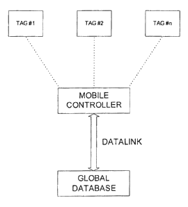
Figure 1 is a block diagram of the main component parts of the system of the
present
invention;
Figure 2 is a functional block diagram of the system and provides more
details; and
Figure 3 is a partly schematic and partly block diagram of an example of a
snow
removal operation using intelligent tags and the system and method of the
present
invention.
BRIEF DESCRIPTION OF THE PREFERRED EMBODIMENT
Briefly, the system is composed, but not limited to, of the following main
components: a Global Database, some or many Intelligent Tags, a Datalink, and
a
Mobile Controller.
The Global Database component is a centralized database containing but not
exclusively the following items. It contains POI (Points of Interests)
application
3
CA 02845115 2014-02-28
information and the ID of the intelligent tags. It also contains Mobile
Controllers
positions and intelligent tags readings (current and past). There is an
outdoor map
sized to have all POls and Mobile Controllers routes within it. And finally it
comprises
the normal route for mobile controller as well as assignations.
The Intelligent Tag component is made from a passive UHF RFID inlay, a polymer
plastic weather-resistant pouch and a custom label. Each tag has a unique RFID
inlay with unique ID. Also the RFID inlay comprises a specific field to each
snow
removal company. Currently, the frequency of operation of this inlay is with
the band
of 902-928 MHz, with a frequency hopping scheme. This band might also be 865-
868 Mhz for European market, or any other allowed frequency for such an
apparatus
depending of the tag technology.
The Datalink component is accomplished with the use of existing cellular link
Internet
network, as GPRS, 3G, 4G LTE or the equivalent. This Datalink securely
connects
each Mobile Controller and a central computer, on which the Global Database is
stored and maintained. Before and during each snow removal run, the Global
Database is transferred to each Mobile Controller (which is named Local
Database)
in order to update routes, assignments, customers and specific notes to all
operators.
The Mobile Controller component is installed in the cab of the machinery, with
the
operator. The Mobile Controller is equipped with classic geolocating
capabilities,
such as GPS. It is also equipped with proximity short range tags reader to
read and
detect Intelligent Tags. There is also apparatus to support communication to
Internet
network through Datalink, such as cellular, GPRS, 3G, 4G LTE or the
equivalent.
The Mobile Controller is also equipped with user interface computer, such as a
tablet, laptop, touch screen, or the equivalent. And finally there is data
storage to
save a delayed copy of the Global Database, which is named Local Database.
Reference numeral 100, the POI, is a point of interest in the snow removal
operation
context. It can identify a drive-way or a delimiting coordinate (example a
parking lot
corner) of a large commercial area that is under snow removal contract.
4
CA 02845115 2014-02-28
Reference numeral 101, the Intelligent Tags, is the technological support of
communicating an unique ID only in short range distance to the Mobile
Controller,
thus providing a mean of identify the current location.
Reference numeral 102, the Mobile Controller, is the sum of technological
means for
positioning the utility vehicle and to provide relevant information to the
operator. It
integrates many currently available possible means of positioning (like GPS,
RF
TAGS and Inertial Navigation System) and returns to the operator the most
accurate
position depending on the best data available from these.
Reference numeral 103, the Proximity RF Tag Reader, is one or many devices
incorporating antenna(s) and the related embedded electronic hardware that
handles
and initiates the communication with the INTELLIGENT TAGS when in the
immediate vicinity of the operator.
Reference numeral 104, the Accelerometer, Gyroscope and Compass, are the
devices that provide and return time varying information of measured
acceleration on
X, Y and Z axis, measured rotation moment as well as the angle relative to the
magnetic north of earth to INS (105).
Reference numeral 105, the Inertial Position & Bearing Integrator (INS), is
the
software function of time integrating the information provided by (104) to
compute
the current position and bearing offset to update (109).
Reference numeral 106, the Touch Screen Display, is a touch screen device that
allows the operator to visualize his vehicle position on the map and also to
get
relevant information to accomplish snow removal run.
Reference numeral 107, the GPS Receiver, calculates its position by precisely
timing
the signals sent by geosynchronous satellites above the earth. It sends
absolute
position of the vehicle and return raw information to the GPS Position / Angle
Producer software module (110).
Reference numeral 108, the Display Manager, is a software module in the Mobile
Controller that controls and manages display and interface control available
to the
operator.
5
CA 02845115 2014-02-28
Reference numeral 109, the Integral Positioning Function & Kernel, is the main
software module that comprises an algorithm integrating all current and
available
information from (105), (111) and (110) and also produces the current most
accurate
position possible and return it to (108) for update.
Reference numeral 110, the GPS Position / Angle Producer, is a software module
that manages data received from the GPS Receiver (107) to get the NMEA
information and to link it to the map and bearing position (109).
Reference numeral 111, the Tag Detection Sweeper, is a software module that
manages the sweeping power of the Proximity RF Tag Reader (103) used to wake-
up Intelligent Tags (101) and initiate communication.
Reference numeral 112, the Local Database, contains a copy of the Global
Database (117) which is needed to associate position of the vehicle with local
position, and to give the operation context (like street maps, snow removal
area
delimitation, position of the Intelligent Tags (101) and their unique ID, last
position of
the other vehicles if applicable).
Reference numeral 113, the Database Updater, makes a periodic copy of the
Local
Database (112) information through the Datalink (114). Thus allowing
information
exchange between the operator vehicle, administration console, and other
vehicles'.
In the event of a communication lost (storm) the operation can resume and
continue
without disturbance based on the last information received.
Reference numeral 114, the Datalink and 116, the Internet Network, allows
through a
RF modem such as cellular, GPRS, 3G, 4G LTE or the equivalent communication
between the Mobile Controller (102) and the Global Database (117). An
encryption
layer is added to the communication to insure business privacy.
Reference numeral 115, the Administration Server, is the server that provides
information to the Mobile Controller (102) and allows the management of the
vehicles, the route, the finance and the client information though the
administration
interface (118). The information is kept on a Global Database (117).
6
CA 02845115 2014-02-28
Reference numeral 117, the Global Database, contains all the business
information
(client names, billing addresses, client locations, etc.). Some of these are
transferred
periodically to provide instructions to the operator through a copy in Local
Database
(112), namely:
ID of the Intelligent Tags (101) and their positions.
Current Mobile Controller positions and tags readings.
Latest outdoor map sized to have all POls and Mobile Controller (102)
routes within it.
Latest normal route for Mobile Controller (102) and assignments.
Reference numeral 118, the Administration Interface, is the software server
application that provides management interface to the administrator in regards
of
these informations:
Position and progress of one or many Mobile Controllers (102).
Management vehicles planned route and the operator assignment.
Management of the vehicles, maintenance, business and technical
information.
Financial and client information (CRM Customer Relationship
Management).
DETAILED DESCRIPTION OF THE INVENTION
The present invention will now be described with reference to the accompanying
drawings. It is understood that other embodiments may be utilized and
structural
changes may be made without changing the scope of the present invention.
All Points of Interests (POI), as referred to 100, are equipped with
Intelligent Tags.
These POls are for example, but not limited to, customers driveways in the
case of
residential snow removal, commercial center and business parkings lot
delimiting
coordinates in the case of commercial snow removal operation, obstacles to
avoid in
a specific snow removal run, etc.
Intelligent Tags, as referred to 101, are proprietary tags currently made with
an UHF
RFID inlay, a plastic protective pocket and a label. The construction of the
Intelligent
Tags may vary upon availability and market pricing of existing UHF RFID Tags.
This
7
CA 02845115 2014-02-28
. .
RFID inlay is compliant with EPC Class 1 Generation 2 international standard
for
such equipment. (Electronic Product Code). This RFID system can be classified
as
an Active Reader Passive Tag (ARPT) system. The active reader inside the
Mobile
Controller transmits interrogator signals and also receives authentication
replies from
passive tags. Each RFID inlay has embedded memory, which allows storage of
unique ID, as well as specific custom parameters, such as location, customer
ID,
type of tags, snow removal contractor unique ID, etc.
The Mobile Controller, as referred to 102, gathers all the means of
positioning the
vehicle (Intelligent Tags and Proximity RF Tag Reader, GPS, Inertial
Navigation) and
produces along with the Local Database a navigation map that includes the
driver's
assigned POls and routes.
The Proximity RF Tag Reader, as referred to 103, is part of the Mobile
Controller.
This Proximity RF Tag Reader is an UHF RFID device made to communicate with
UHF RFID inlays in Intelligent Tags. This device is emitting power and control
data to
start communication with inlays in line of sight and within a short distance
range, in
the order of 5-8 meters. The reader gets inlay memory content and sends
received
data to the software module named Tag Detection Sweeper, referred as 111. This
software module manages the power of the Proximity RF Tag Reader in a sweeping
scheme. This sweeping scheme gives a rough estimate about the distance between
the reader and the tags since the radiation power of an RF device decreases to
the
inverse square of the distance. This software module also manages other
aspects of
the Proximity RF Tag Reader to intercept tags in a constant manner without any
interference or disruption.
The Mobile Controller (102) comprises motion sensors that are embedded or
external to measure acceleration, rotation moment and orientation relatively
to the
magnetic north. These sensors are accelerometers, gyroscope and compass, as
referred to 104. These sensors provide raw data to the Inertial position &
bearing
integrator (INS) software module, referred as 105. This software module
continuously computes dead reckoning navigation of position, orientation and
velocity of the Mobile Controller without the need of external references,
like GPS
signals from satellites. The dead reckoning navigation provides guidance
between
Intelligents Tags reading in order to compensate the lack of GPS signal from
any
8
CA 02845115 2014-02-28
disruption. The INS navigation has however important limitations due to
integration
drift error. This navigation method is a backup and provide good indications
between
scan of Intelligent Tags. When a tag is scanned, absolute position is
corrected from
known position data in the Local Database associated with this particular tag.
The operator controls the Mobile Controller (102) through the use of a Touch
screen
display, as referred to 106. This display is managed with Display manager
software
module (108). The display shows all relevant information to help the operator
to
navigate and to manage customers in a snow removal run. It shows road maps,
snow removal routes, customers ID, special notes, vehicle maintenance
information,
etc.
The Mobile Controller (102) comprises a GPS receiver, as referred to 107. This
GPS
receiver is either embedded or external to the Mobile Controller itself. It
transmits
raw position data to the GPS position / angle producer software module, as
referred
to 110. This software module manages data from the GPS receiver to get the
position, velocity and orientation data in order to link them to the map and
routes.
The Mobile Controller (102) has a Datalink, as referred to 114. This Datalink
is a
cellular link connected to the Internet network, and to the centralized Global
Database, as referred to 117. Datalink is using existing technology for remote
data
transmission, such as cellular network GPRS, 3G, 4G LTE or any equivalent data
network. The Datalink is encrypted using AES (Advanced Encryption Standard) or
equivalent encryption algorithm to protect privacy of data exchanges.
The Administration console, as referred to 115, comprises the Global Database
(117) and an Administration interface, as referred to 118. This software
module is the
central management tool intended to the administrator of the system. It
comprises
Vehicle Management module, Route management module, Finance management
module and finally, but not limited to, Client management module. The
Administration interface allows access to the position and the progress of the
fleet of
Mobile Controllers. It is also the center component to manage and display
customer
information, known as CRM (Customer Relationship Management).
9
CA 02845115 2014-02-28
. .
It is within the ambit of the present invention to cover any obvious
modifications of
the preferred embodiments described herein, provided such improvements fall
within
the scope of the appended claims.