Note: Descriptions are shown in the official language in which they were submitted.
,
Inner Cylinder of Explosion-Venting-Type Aerosol Fire
Extinguishing Device
Technical field of the invention
The present invention relates to the field of fire fighting and extinguishing
technologies, and more particularly to an aerosol fire extinguishing device
capable of anti-explosion, venting pressure and reducing a recoil force.
Backdround of the invention
Generally, an existing aerosol fire extinguishing device mainly includes an
inner cylinder body, a cylinder cover component arranged on the cylinder body,
and an ignition composition coated by a thermal insulation material, an
ignition
head, a coolant and a ceramic chip etc. arranged in the inner cylinder body in
turn. Normally, after the ignition head ignites the ignition composition, a
great
amount of aerosol smoke is generated by a relatively fast stratified
combustion
of a grain. These high temperature aerosols are cooled by a coolant layer and
then spouted out by a spout of the cylinder cover component to act on a fire
source directly to suppress a fire. However, a coating defect, a pyrotechnic
grain crack or a serious blockage of a gas channel may lead to a sudden rise
of the pressure in the cylinder body to deflagrate the grain. A gas with an
ultra-high pressure which is increased quickly is vented forward rapidly to
thrust the spout aside and strike the nozzle out at an extremely high speed,
thus causing a very large recoil force. The powerful recoil force drives the
cylinder body to move backwards rapidly, which is very easy to cause a
serious injury to an operator. At the same time, after explosion ventilation,
a
hot air stream will be accumulated in the cylinder body, and the inner
cylinder
cover component etc. of the aerosol fire extinguishing device will also
disengage with the cylinder body at an extremely high speed and fly outwards
for a relatively long distance, which may cause other accidents or even more
1
CA 2845428 2018-12-12
serious accidents, such as an explosion of the cylinder body of the inner
cylinder, and the like when an accumulated pressure is too high.
However, almost all inner cylinder bodies of existing aerosol fire
extinguishing devices lack of explosion ventilation (prevention) measures. A
method of pressing a front cover tightly is applied at most, which cannot vent
explosion safely and still fails to solve the problems above. Therefore, all
inner
cylinder bodies of the existing aerosol fire extinguishing devices have
potential
safety hazards to great personal injuries or material damages caused by a
powerful recoil force generated after deflagration of an composition, an
explosion of a cylinder body and detachment of an inner cylinder cover
component.
Summary of the invention
To solve the problem of potential safety hazards to personal injuries or
material damages caused by a recoil force generated after deflagration of a
grain, an explosion of a cylinder body thereof or detachment of a component
due to the lack of any explosion prevention and pressure venting measures for
an aerosol fire extinguishing device in the prior art, the present invention
provides an inner cylinder of an explosion-venting-type aerosol fire
extinguishing device.
A technical means applied by the present invention is that:
An inner cylinder of an explosion-venting-type aerosol fire extinguishing
device, comprising: a cylinder body 3 and a cylinder cover component 4
arranged on one end of the cylinder body 3, wherein an explosion-venting
device is also arranged on the cylinder body 3; the explosion-venting device
comprises: a friction layer 11, a connecting rod 12, a guiding unit 13, and a
limiting device 14, the connecting rod 12 are connected with the cylinder
cover
component 4; the friction layer 11 is provided between the connecting rod 12
and the cylinder body 3; the friction layer 11 provides a frictional
resistance and
a buffering force for the connecting rod 12 when the connecting rod 12 is
2
CA 2845428 2018-12-12
displaced, under the guidance of the guiding unit 13, along a direction
towards
which a hot air stream of the cylinder body 3 is jetting; the guiding unit 13
is a
device capable of providing guidance for the connecting rod 12 when the
connecting rod 12 is moving; the limiting device 14 is a device capable
affixing
the connecting rod 12 and capable of limiting the connecting rod 12 when an
extremity of the connecting rod 12 slides to the cylinder cover component 4.
During a process in which the cylinder cover component 4 is separated from
the limiting device 14 and slides forwards, a original high pressure gas in
the
cylinder body will be dispersed rapidly because of expansion of an outlet
(venting pressure outlet), and will be consumed and transferred through a
physical process so as to be a vent explosion, i.e. the process in which the
cylinder cover component 4 slides forwards is an explosion-venting process of
the cylinder body 3.
The guiding unit may be a guiding ring 15 fixedly connected with the
connecting rod 12, or may be also a guiding groove or a slide rail provided on
an outer wall of the cylinder body 3 and capable of making the connecting rod
12 slide axially along the guiding groove, or other structures having a
guiding
function.
The limiting device 14 mainly includes a flanging 16 fixedly connected with
the cylinder body 3 and a clamping claw 17 for fixing the connecting rod 12,
or
a structure as long as the structure can fix the connecting rod 12 on one hand
and stop the connecting rod 12 from being separated from the cylinder body 3
on the other hand, wherein the flanging 16 may be integrated with the cylinder
body 3 to reinforce the structure thereof and effectively stop an extremity of
the
connecting rod 12 from being separated from the cylinder body 3; a buffer 18
is
further arranged between the flanging 16 and the guiding ring 15 mainly to
buffer a collision force between the extremity of the connecting rod 12 and
the
cylinder body 3 or a collision force between the extremity of the connecting
rod
2 and the flanging 16 so as to prolong a collision process while consuming, by
releasing elastic energy, a part of kinetic energy generated after a
deflagration.
3
CA 2845428 2018-12-12
The connecting rod 12 may be further fixedly connected with the cylinder
cover component 4 or integrated with the cylinder cover component 4, thus
effectively preventing the cylinder cover component 4 from flying outwards to
prevent other accidents caused thereby.
The displacement of the connecting rod 12 of the present invention is
ranged from 30mm to 80mm, preferably 50mm to 60mm. A displacement
which is too large cannot reduce a recoil force. However, if a displacement is
too small, the kinetic energy cannot be consumed thoroughly and the cylinder
cover component is very likely to get rid of the blockage of the limiting
device
14. Once the cylinder cover component is separated from the cylinder body, a
powerful recoil force will be generated. Therefore, appropriate displacement
control is of great importance. However, the displacement of the connecting
rod 12 may be adjusted appropriately according to a specific application
environment, as long as an optimal effect can be achieved.
A spout of the cylinder cover component 4 is sealed by a rubber plug 10 to
be sealed against moisture.
A sealing ring 9 is arranged on the junction of the cylinder cover
component 4 and the cylinder body 3. The section of the sealing ring 9 is
circular, thus reducing cost and improving the sealing effect.
The deflagration of the present invention means that a pyrotechnic grain,
which is cracked or broken or has an ineffective external coating, is ignited
to
burn heavily within an extremely short period of time that is only about 1/10
of
normal stratified combustion. After the deflagration of the grain, a great
deal of
high pressure and high temperature gases will be generated instantaneously.
The working principle of the present invention is that: when the grain 7 is
deflagrated, the gas pressure in the grain will increase suddenly and rapidly
and the rubber plug 10 on the cylinder cover component 4 will be thrust apart
easily by a high pressure gas. Hence, pressure relief of the gas begins.
However, there is no time for a normal spout to vent the pressure because of
the deflagration, and pressure in the cylinder body 3 will be accumulated to
4
CA 2845428 2018-12-12
form a high pressure gas. The high pressure gas will thrust apart the clamping
claw 7 which is originally bent with 90 degrees and used for tightly clamping
the connecting rod 12 and the cylinder body 3. Thus the clamping claw 17 is
loosened and thrust apart and the cylinder cover component 4 will be
separated from the cylinder body 3 and slide outside. When the clamping claw
17 is loosened and thrust apart, the potential energy of deformation of the
clamping claw is overcome by explosive energy, which inevitably consumes a
part of the explosive energy (first method of explosion ventilation and energy
consumption). Subsequently, the cylinder cover component 4 that has slid
outside drives the connecting rod 12 and the guiding ring 15 to slide along an
axis of a cylinder wall. In this process, because of the friction layer 11, a
relatively large frictional resistance will be generated during the process of
the
cylinder cover component 4 and the guiding ring 15 sliding on the outer wall
of
the cylinder body 3, thus consuming a part of kinetic energy of an forward
impact of the cylinder cover component 4 (second method of explosion
ventilation and energy consumption). When the guiding ring 15 and the
cylinder cover component 4 slide forward to the vicinity of a top edge of the
inner cylinder body 3, the buffer 18 will be squeezed by the guiding ring 15
and
the flanging 16 arranged on and the cylinder body 3 so as to absorb a part of
the kinetic energy (third method of explosion ventilation and energy
consumption). When the two parts slides oppositely to squeeze the buffer 18 to
the limit so that the buffer 18 cannot be squeezed any more, the buffer 18
will
react upon the two objects which are close oppositely and a part of stored
elastic potential energy will be released so as to further stop the two
objects
from getting closer. Therefore, a part of kinetic energy is also consumed
(fourth
method of explosion ventilation and energy consumption). Finally, a front end
of the guiding ring 15 is collided on the flanging 16 on the inner cylinder
body 3,
and partial elastic or plastic deformation of the flanging 16 can also
effectively
stop a front cover and a sliding ring from moving forwards (fifth method of
explosion ventilation and energy consumption). Thus, the energy generated by
CA 2845428 2018-12-12
the whole deflagration is almost exhausted, and the connecting rod and the
front end stops displacement. Therefore, there will be no relatively large
recoil
force acting on the cylinder body 3, and the danger that the cylinder cover
component 4 is thrust outwards can be effectively prevented. During the
process in which the cylinder cover component 4 is separated from the limiting
device 14 and slides forwards, the original high pressure gas in the cylinder
body will be dispersed or consumed rapidly because of the expansion of the
outlet (venting pressure outlet), i.e. the process that the cylinder cover
component 4 slides forwards is a venting pressure process of the cylinder
body,
thus preventing an danger of the explosion of the whole body or the
flying-separation of an component, and the limited displacement of the
connecting rod, i.e. the final limitation, is to reduce the recoil force and
prevent
injuries and damages caused by the generated recoil force.
The present invention is an inner cylinder of an explosion-venting-type
aerosol fire extinguishing device having the following main advantages:
1. the present invention, an explosion-venting device is further arranged
on an inner cylinder body, which consumes and relieves a recoil force or a
forward impact force generated after a deflagration of an composition mainly
through consuming kinetic energy, generated by the deflagration during a
moving and limiting process of the explosion-venting device, so as to avoid
injuries or damages generated after the deflagration of a gain;
2. a connecting rod of the present invention is connected with a cylinder
cover component, a flanging and a clamping claw structure are applied, thus
effectively controlling a movement of the connecting rod. The structure can
effectively prevent a powerful impact force from acting on the cylinder cover
component to thrust the cylinder cover component out of a cylinder body, thus
preventing an accident caused by the cylinder cover component after the
cylinder cover component flies outwards;
3. a flanging of a limiting device and the inner cylinder body of the present
invention are integrated so that the structure is firmer with higher impact
6
CA 2845428 2018-12-12
resistance;
4. the present invention is simple in structure and convenient for
installation.
Brief Description of the Drawings
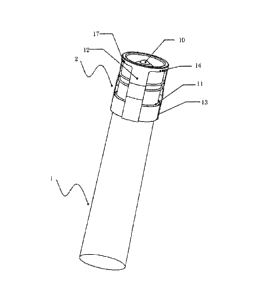
Fig. 1 is a structural diagram of an inner cylinder of the present invention;
Fig. 2 is a sectional view of an inner cylinder of the present invention.
In the figures: 1-aerosol fire extinguishing device; 2-explosion-venting
device; 3-cylinder body; 4-cylinder cover component; 5-ceramic honeycomb
cooling layer; 6-coolant; 7-grain; 8-ignition head; 9-sealing ring; 10-rubber
plug;
11-friction layer; 12-connecting rod; 13-guiding unit; 14-limiting device;
15-guiding ring; 16-flanging; 17-clamping claw; 18-buffer, 19-heat
preservation
and insulation layer.
Detailed description of the invention
Preferred embodiments of an inner cylinder of an explosion-venting-type
aerosol fire extinguishing device of the present invention will be further
described in combination with the accompanying drawings.
Referring to Fig. 1 and Fig. 2, the inner cylinder of the aerosol fire
extinguishing device 1 of the present invention may adopt an inner cylinder
with an existing structure, on which an explosion-venting device is added to
solve the problem that an existing aerosol fire extinguishing device 1 fails
to
prevent explosion and vent pressure; or may adopt other cylinders which
relates to the inner cylinders of aerosol fire extinguishing devices with
explosion prevention and pressure venting requirements.
The inner cylinder of the present embodiment includes a cylinder body 3.
A cylinder cover component 4 is further arranged on a top end of the cylinder
body 3. A ceramic honeycomb cooling layer 5, a coolant 6, a grain 7 and an
ignition head 8 arranged on a front end face of the grain 7 are arranged in
the
cylinder body 3 in turn. Generally, the cylinder body 3 and the cylinder cover
7
CA 2845428 2018-12-12
component 4 are hermetically connected via a sealing ring 9, wherein the
section of the sealing ring 9 may be square, circular, or in other shapes. The
cylinder cover component 4 includes a spout and a horn nozzle, and the center
of the spout directly faces the center of the horn nozzle. The spout may be
sealed by a rubber plug 10 or an aluminum foil. In addition, the ceramic
honeycomb cooling layer 5, on one hand, can fix the coolant 6 to prevent the
coolant 6 from dropping out, on the other hand, has a physical cooling effect
to
cool a high temperature hot aerosol. Generally, the ceramic honeycomb
cooling layer 5 may be arranged on a front end of the coolant 6, or may be
also
arranged in the middle of the coolant 6, or may be also arranged on both the
front end and the middle of the coolant 6, and the positions and number
thereof are determined according to actual application conditions. One end
with a larger diameter of the horn nozzle of the present invention is
connected
with the honeycomb cooling layer to guide the aerosol to be spouted out from
the spout, and the horn nozzle may be integrated with a cylinder cover. A heat
preservation and insulation layer 19, which has a heat preservation and
insulation function, may be further added between the grain 7 and an inner
wall
of the cylinder body 3, thus preventing heat generated after ignition of the
aerosol from being dispersed to burn surrounding personnel or materials.
The explosion-venting device 2 of the present invention mainly includes a
friction layer 11, a connecting rod 12, a guiding unit 13, a limiting unit 14
and a
buffer 18, wherein the connecting rod 12 is connected on the cylinder cover
component 4 and may be fixedly connected with the cylinder cover component
4 via welding and riveting etc., or may be directly provided as an integral
structure so as to realize a higher structural strength. The friction layer 11
may
be one or more rubber rings, or silica gel layers, or other materials that can
provide a sufficient frictional resistance for axial sliding of the connecting
rod
12. The friction layer 11 may be arranged between the connecting rod 12 and
the cylinder body 3, or may be directly fixed on an inner side of the
connecting
rod 12. When the connecting rod 12 shifts axially along the cylinder body 3
8
CA 2845428 2018-12-12
under the guidance of the guiding unit 13, the friction layer 11 provides a
frictional resistance and a buffering force for the connecting rod. The
guiding
unit 13 is an device that can provide guidance for the connecting rod 12 when
the connecting rod 12 is moving. The guiding unit may be a guiding ring 15
fixedly connected with the connecting rod 12, or may be also a guiding groove
arranged on an outer wall of the cylinder body 3 and capable of making the
connecting rod 12 slide along the guiding groove, or a slide rail, or other
structures with a guiding effect. The guiding structure can prevent the
connecting rod 12 from being displaced or clamped during a moving process
of the cylinder body 13. When a guiding ring 15 is applied for guiding, the
guiding ring 15 and an extremity of the connecting rod 12 may be fixedly
connected, or may be directly provided as an integral structure. The limiting
device 14 of the present invention is an device that can fix the connecting
rod
12 and limit the connecting rod 12 when the connecting rod 12 slides to the
cylinder cover component 4. When the extremity of the connecting rod 12
reaches a position as shown of the cylinder cover component 4, the
connecting rod is limited by the limiting device 14. The limiting device 14
mainly includes a flanging 16 and a clamping claw 17, wherein the flanging 16
and the cylinder body 3 are fixedly connected, or may be also directly
provided
as an integral structure while one end of the clamping claw 17 is fixed on the
connecting rod 12 and the other end is clamped with the cylinder body 3, which
is mainly used for fixing the connecting rod 12. The connecting rod 12 may be
also integrated with the clamping claw 17, or the limiting device 14 of the
present invention may be also other structures, which can fix the connecting
rod 12 on one hand, and stop or prevent the connecting rod 12 from being
separated from the cylinder body 3. The flanging 16 of the present invention
may be also arranged on a lug boss of the opening of the cylinder body, and
may be also integrated with a guiding groove. The structure of the flanging is
determined according to an application environment. When the guiding unit 13
adopts a guiding ring 15, the buffer 18 may be further arranged between the
9
CA 2845428 2018-12-12
guiding ring 15 and the flanging 16 for buffering a collision force between
the
guiding ring 15 or the extremity of the connecting rod 12 and the cylinder
body
3 or the flanging 16 to prolong a collision duration and consume, by releasing
elastic potential energy of the buffer, a part of kinetic energy generated
after a
deflagration.
The displacement of the connecting rod 12 of the present invention is
controlled within 30mm to 80mm, preferably 50mm to 60mm, because an
excessive displacement cannot reduce the recoil force. However, if the
displacement is too small, the kinetic energy cannot be consumed thoroughly
and the cylinder cover component is very likely to get rid of the blockage of
the
limiting device 14. Once the cylinder cover component is separated from the
cylinder body, a powerful recoil force will be generated. However, the
displacement of the connecting rod 12 may be adjusted appropriately
according to a specific application environment as long as an optimal
explosion venting effect can be achieved.
When the grain 7 in the inner cylinder is ignited and released normally, a
hot gas is released from the spout of the cylinder cover component 4 without
generating a overlarge air stream, then the explosion-venting device 2 will
not
be started. The connecting rod 12 is fixed on the cylinder body 3 by the
clamping claw 17 and will not move axially along the cylinder body 3 to be
displaced. Only when an composition is deflagrated accidentally and a
powerful hot air stream pushes the cylinder cover component 4 and the
connecting rod 12 to move in a direction that the hot air stream is jetting
towards, the clamping claw 17 of the limiting device 14 is detached under the
action of a powerful impact force on one hand, during which a part of kinetic
energy of impact kinetic energy is consumed. Pushed by the hot air stream,
the connecting rod 12 drives the guiding ring 15 to slide axially along the
outer
wall of the cylinder body 3 to be displaced. During the moving process, the
friction layer 11 generates a frictional resistance on the guiding ring to
consume a part of the impact kinetic energy. When the extremity of the
CA 2845428 2018-12-12
connecting rod 12 reaches the spout of the cylinder body 3, the flanging 16 of
the limiting device 14 fixed on the cylinder body 3 prevents the extremity of
the
connecting rod 12 from being separated from the cylinder body 3. At the
moment, the buffer 18 arranged between the flanging 16 and the guiding ring
15 functions to consume a part of the impact kinetic energy with the
elasticity
of the buffer. In addition, the buffer buffers the powerful impact force
between
the extremity of the connecting rod 12 and the flanging 16. When the final
kinetic energy acts, in the form of collision, on the flanging 16, the
flanging 16
is distorted elastically or plastically to consume all remaining kinetic
energy.
Thus the powerful impact kinetic energy generated by the deflagration of the
grain 7 will be consumed or dispersed in the whole process, thus avoiding
injuries and damages caused by the powerful impact kinetic energy.
The inner cylinder of the present invention is not limited to the structures
in
the embodiments above, and is not only applicable to a portable fire
extinguishing device or a fixed fire extinguishing device, but also applicable
to
other devices that involve the problem of pressure venting and explosion
prevention.
11
CA 2845428 2018-12-12