Note: Descriptions are shown in the official language in which they were submitted.
CA 02845436 2014-03-11
r..
PATENT APPLICATION
of
Benjamin Michael Allen
for
DECORATIVE POP-UP FLANGE REPLACEMENT
CA 02845436 2014-03-11
DECORATIVE POP-UP FLANGE REPLACEMENT
Background and Summary of the Disclosure
[0001] The present invention relates to the field of sink drains. More
particularly, the present
invention relates to improved substitute and replacement components for sink
drains.
[0002] Pop-up drains for use within sink basins are well known. The flange
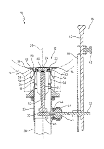
of a pop-up
drain typically surrounds the outlet in the bottom center of the sink basin.
The flange helps
center a drain pipe and directs water therethrough. Often, this flange may
become dirty or
corroded, and/or the finish or material may no longer provide a pleasing
appearance, thus
requiring replacement. Additionally, when replacing a faucet supported above
the sink basin, the
pop-up drain may likewise require replacement in order for the faucet and the
pop-up drain to
have matching material finishes.
[0003] Installation of a new flange in a sink usually requires removal of
the original flange
using various tools. For example, at times, removal of the flange may require
striking the
underside of the flange with a rubber mallet or other heavy device to jar the
flange loose from the
sink basin. Further, replacing the flange in a sink usually requires the
replacement of the pop-up
stopper as well, because the finishes or materials of the flange and the pop-
up stopper should
preferably match, making them look more aesthetically pleasing.
[0004] Thus, an alternative to this complicated disassembly is desirable.
An overfitting
substitute flange, accompanied by a matching replacement pop-up stopper, would
allow a person
to forego the use of tools and avoid having to negotiate the underside of the
sink basin. Such a
substitute flange would prevent complicated disassembly and simplify the
potentially difficult
process of improving the appearance of a sink.
[0005] According to an illustrative embodiment of the present disclosure, a
drain
replacement assembly includes a drain pipe having an annular side wall
defining a drain opening,
and a drain annular seat extending radially outwardly from the side wall. A
secondary flange
includes a downwardly extending annular lip sized to fit in the drain opening,
and a flange
annular seat extending radially outwardly from the annular lip. The annular
lip is at least
partially inserted within the drain opening. The flange annular seat is
positioned above the drain
pipe to conceal the drain annular seat.
1
CA 02845436 2014-03-11
[0006] According to another illustrative embodiment of the present
disclosure, a drain
= replacement assembly includes a flange having a downwardly extending
annular lip, a flange
annular seat extending radially outwardly from the annular lip, and at least
one malleably
bendable finger extending downwardly from the annular lip and configured to be
bent into at
least one overflow hole in a drain pipe.
[0007] According to a further illustrative embodiment of the present
disclosure, a drain
replacement assembly includes a flange having a downwardly extending annular
lip, a flange
annular seat extending radially outwardly from the annular lip, and at least
one finger extending
downwardly from the annular lip and configured to be retained within a drain
pipe. A stopper is
received within an opening defined by the annular lip of the flange. The
stopper includes a
plunger and a sealing ring supported by the plunger. The stopper is adjustable
between a
lowered sealed position and a raised unsealed position. The sealing ring is in
abutment with the
annular lip when the stopper is in the sealed position, and spaced from the
annular lip when the
stopper is in the unsealed position.
[0008] Additional features and advantages of the present invention
will become apparent to
those skilled in the art upon consideration of the following detailed
description of the illustrative
embodiment exemplifying the best mode of carrying out the invention as
presently perceived.
Brief Description of the Drawings
[0009] The detailed description of the drawings particularly refers
to the accompanying
figures in which:
[0010] Fig. 1 is a cross-sectional view of a replacement assembly as
part of a sink drain
assembly in accordance with an illustrative embodiment of the present
invention;
[0011] Fig. 2 is an exploded perspective view of the replacement
assembly of Fig. 1;
[0012] Fig. 3 is a detailed side cross-sectional view of the
replacement assembly of Fig. 2,
during an intermediate installation step;
[0013] Fig. 4 is another detailed side cross-sectional view of the
replacement assembly of
Fig. 2, fully installed within a drain pipe; and
[0014] Fig. 4A is a detail view of Fig. 4.
[0015] Corresponding reference characters indicate corresponding
parts throughout the
several views. Although the drawings represent embodiments of the present
invention, the
2
CA 02845436 2014-03-11
drawings are not necessarily to scale and certain features may be exaggerated
in order to better
illustrate and explain the present invention. Although the exemplification set
out herein
illustrates embodiments of the invention, in several forms, the embodiments
disclosed below are
not intended to be exhaustive or to be construed as limiting the scope of the
invention to the
precise forms disclosed.
Detailed Description of the Drawings
[0016] Referring initially to Fig. 1, a sink drain assembly 10 according to
an illustrative
embodiment of the present invention is shown. Sink drain assembly 10 includes
a drain
replacement assembly 12, a sink basin 14, a drain pipe 16, and a lift rod
assembly 18.
Specifically, drain replacement assembly 12 is a replacement flange and
stopper assembly. More
particularly, the drain replacement assembly 12 includes a substitute flange
20, having a flange
opening 22, that is supported within drain pipe 16, and a replacement pop-up
plug or stopper 24
(hereinafter "stopper") that is received within flange opening 22.
[0017] Drain pipe 16, of a type well-known in the art, provides an outlet
for water from sink
basin 14. Drain pipe 16 includes an annular, illustratively cylindrical, side
wall 23 defining a
longitudinal axis 25. A stopper 24 may be inserted down into drain pipe 16 to
stop the flow of
water therethrough and out of sink basin 14. Drain pipe 16 extends from upper
drain opening 26
downward to tail piece 28 that extends below from near where a pivot tip 30 is
connected with a
pivot rod 32 of lift rod assembly 18. Drain annular flange/seat 34 defines
drain opening 26
(hereinafter "drain seat," to prevent confusion with substitute flange 20) and
extends radially
outwardly from side wall 23 around the bottom of sink basin 14. Below drain
opening 26, a
plurality of overflow openings or holes 36 are circumferentially situated
within side wall 23 of
drain pipe 16 to receive water from overflow opening(s) (not shown) in an
upper portion of sink
basin 14.
[0018] Lift rod assembly 18, of a type well-known in the art, seals and
unseals drain pipe 16.
Clevis strap 38 is affixed to lift rod 40 via set screw 42 so that clevis
strap 38 moves
correspondingly up or down as lift rod 40 is raised or lowered, respectively.
Lift rod 40 may be
supported by a faucet (not shown) positioned above the sink basin 14. Lift rod
40 through clevis
strap 38 is illustratively connected to pivot rod 32, which is supported for
pivoting movement
about ball 43 received within pivot seat 44, and secured therein via retaining
nut 46. Pivot rod
3
CA 02845436 2014-03-11
32 has pivot tip 30 that extends horizontally into drain pipe 16 to engage
bottom loop 48 of
adjustment bolt or post 50. Pivot tip 30 can either be received within bottom
loop 48, to prevent
upward pulling-out removal of stopper 24 from drain pipe 16 (for tamper
resistance as in public
washrooms), or bottom loop 48 can rest atop pivot tip 30.
10019] In Fig. 1, when lift rod 40 is lifted up, pivot rod 32 pivots within
pivot seat 44,
thereby allowing stopper 24 to move downwardly due to gravity and seal flange
opening 22. In
the embodiment where bottom loop 48 is placed atop pivot tip 30, lifting lift
rod 40 up simply
permits stopper 24 to move towards flange opening 22 and, when water
accumulates within sink
basin 14, stopper 24 is urged downward by the pressure of the accumulating
water to seal flange
opening 22. When lift rod 40 is pressed down, pivot rod 32 pushes stopper 24
upward to unseal
flange opening 22 and allow passage of water from sink basin 14 into drain
pipe 16.
[0020] Referring now to Fig. 2, replacement flange and stopper assembly 12
is shown in an
exploded, perspective view with the original stopper (not shown) having been
removed from
drain pipe opening 26. As noted above, drain pipe 16 has four overflow holes
36 below drain
seat 34 evenly situated (i.e., circumferentially spaced) around its
cylindrical circumference of
side wall 23. Drain seat 34 extends length L1 radially outwardly from opening
26 defined by
side wall 23 of drain pipe 16 in a collar-like (i.e., annular) manner. Drain
opening 26, which
leads downward and extends through drain pipe 16, has an inner diameter DI.
[0021] Flange 20 covers drain seat 34 to provide a substitute material
and/or finish in the
bottom of sink basin 14. Shaped like a ring, flange 20 has an axially
downwardly extending
annular side wall or lip 52 with four malleably bendable fingers 54 and 56
extending axially
downwardly therefrom. Fingers 54 and 56 and annular lip 52 extend axially
downward to help
guide and center flange 20 within opening 26 of drain pipe 16 during
installation. In the
illustrative embodiment, flange 20 is constructed of a single piece of sheet
metal that is stamped
into the shape shown in Fig. 2, with the four malleably bendable fingers 54
and 56 all formed
integrally within flange 20. Fingers 54 and 56 may define retainers, one or
more of which are
formed or bent radially outwardly into overflow holes 36 to secure flange 20
to drain pipe 16.
[0022] This single-piece design of flange 20 provides simplicity and cost-
effectiveness
because it lacks extra parts and multiple materials. As shown in the
illustrative embodiment of
Fig. 3, fingers 54 have length L2 and fingers 56 have a length L3 because all
four malleably
bendable pieces, formed integrally with flange 20 from a single sheet, cannot
all extend equal
4
CA 02845436 2014-03-11
lengths L2 from annular lip 52 due to manufacturing constraints. Thus, fingers
56 are shorter
than fingers 54 to allow the single-piece construction of substitute flange
20. In other
embodiments, the ratio of L2 to L3 may be adjusted. Further, providing fingers
54 and 56 with
different lengths L2 and L3, provides greater bending compatibility with
different drains having
different sizes, configurations and arrangements of overflow holes 36.
[0023] Flange 20 includes an annular flange seat 58 that extends length L4
radially outwardly
from opening 22 defined by lip 52 in a collar-like manner similar to drain
seat 34. For flange 20
to accommodate sink basins 14 and drain pipes 16 of various sizes and designs,
L4 should be
greater than LI. This larger seat 58 allows flange 20 to completely cover a
wide variety of
different sized drain seats 34. In other words, the outer edge 59 of the
flange seat 58 is
positioned radially outwardly from the outer edge 35 of the drain seat 34. In
certain illustrative
embodiments as shown in Fig. 4A, the flange 20 includes a downwardly bent lip
61 that partially
wraps around outer edge 35 of the drain seat 34. The lip 61 provides
additional structural
rigidity to the flange 20 and assists in covering the drain seat 34.
[0024] Similar to drain pipe 16, flange 20 defines flange opening 22 having
diameter D2,
which, when flange 20 is fully installed, leads downwardly into drain pipe 16.
Diameter D2 of
flange opening 22 is smaller than diameter Di of drain pipe opening 26 to fit
flange 20 and its
axially downwardly extending members (e.g., lip 52, and fingers 54 and 56)
into drain opening
26.
[0025] Stopper 24 is designed to seal and unseal flange opening 22, thereby
selectively
preventing and allowing outflow through the bottom of sink basin 14,
respectively. Stopper 24
illustratively includes a plunger 64 supported for sliding movement within
flange opening 22.
[0026] A cap 60 is supported by an upper end of plunger 64, and adjustment
bolt or post 50
is threadably received within a lower end of plunger 64. Immediately below cap
60, sealing ring
62, having diameter D3, abuts the inner surface of annular lip 52 on flange 20
to seal sink basin
14. To create this seal, D3 is substantially equal to D2 so that stopper 24
fits tightly within flange
opening 22. Thus, D3 is smaller than the diameter of the sealing ring of the
original stopper.
Cap 60, constructed of a thin rigid material having the same exterior finish
as flange 20, is at the
top of stopper 24, above sealing ring 62. Cap 60 may be formed of a stainless
steel sheet affixed
to the plunger 64 in a conventional manner, for example by crimping and/or
adhesives.
CA 02845436 2014-03-11
[0027] In Fig. 2, stopper 24 has bottom loop 48 for engaging pivot tip 30
(in two possible
ways, as previously described and shown in Fig. 1) so that stopper 24 can be
axially adjusted by
lift rod 40 to seal and unseal drain pipe 16 using lift rod assembly 18. The
downward reach of
bottom loop 48 may be decreased or increased (i.e., axially adjusted) by
threading adjustment
bolt or post 50 into and out of plunger 64, respectively. Plunger 64 may be
constructed of a
plastic, polymer, or other corrosion-resistant material.
[0028] For aesthetic purposes, it is desirable that both flange 20 and cap
60 be constructed of
matching materials and/or have a matching finish. These materials or finishes
may include
polished chrome, copper, stainless steel, brass, or nickel, among several
others. In one
illustrative embodiment, both flange 20 and cap 60 are formed of stainless
steel.
[0029] Installation of flange 20 and stopper 24 is illustrated in Figs. 2-
4. Fig. 2
illustrates drain pipe 16 with the original stopper (not shown) having been
removed and
secondary flange 20 and replacement stopper 24 in position just prior to
insertion. During
assembly of the illustrative embodiment, flange 20 is installed first, and
stopper 24 follows next.
[0030] Referring now to Fig. 3, flange 20, the first component to be
installed in drain pipe 16
in the illustrative embodiment, is shown as having been partially installed,
placed over the top of
drain seat 34. Stopper 24 is illustrated as being uninstalled and above drain
pipe 16. Each finger
54 is positioned along the edge of an adjacent overflow hole 36, but has not
been bent under the
upper edge 65 of each overflow hole 36 to secure flange 20. Instead, each
finger 54 extends
substantially and axially perpendicularly from annular lip 52.
[0031] In certain illustrative embodiments, when flange 20 is placed atop
drain pipe 16, a
space 66 may exist between the underside of flange seat 58 and the topside of
drain seat 34
because of the angle at which drain seat 34 bends radially outwardly may be
different from the
angle at which flange seat 58 bends radially outwardly. Space 66 can be sealed
and filled using
plumbers putty (not shown) or any one of a number of different adhesives (not
shown). In
certain illustrative embodiments, double faced adhesive tape may be used
between drain seat 34
and flange seat 58. Sealing these two seats 34 and 58 together may provide a
tighter seal along
drain pipe 16 to prevent leakage into the area beneath sink basin 14, and may
provide a cleaner
and more flush surface along the bottom of sink basin 14.
[0032] As shown in Fig. 4, each finger 54 of flange 20 is partially bent
through an adjacent
overflow hole 36, illustratively hooking onto the upper edge 65 of each
adjacent overflow hole
6
CA 02845436 2014-03-11
36. The excess lengths of fingers 54 extend radially out of drain pipe 16.
Advantageously, it can
be contemplated then, that these excess lengths of each finger 54 allow flange
20 to
accommodate sink drains of various sizes and overflow holes of various depths
and
arrangements. Further, while fingers 54 are illustrated as partially bent in
Fig. 4, fingers 54 may
be bent further upward to more tightly hook the upper edges 65 of overflow
holes 36, or hooked
to the side of the edges of overflow holes 36, to secure flange 20 to drain
pipe 16. The various
ways to engage fingers 54 to drain pipe 16 are not limited to the illustrated
bending shown in
Fig. 4.
[0033] Referring to Fig. 4, stopper 24, the second component to be
installed in the illustrative
embodiment, and flange 20, are both shown fully installed. Stopper 24 fits
within flange 20 and
extends axially downward to engage pivot tip 30 as previously described and
shown in Fig. 1.
Here, both stopper 24 and flange 20 form a substantially flush surface along
the sink basin 14.
This creates an aesthetically pleasing sink basin 14 appearance and an
effective seal because of
the approximate equivalence of diameter D2 of the flange opening 22 and
diameter D3 of the
sealing ring 62.
[0034] Although the invention has been described in detail with reference
to certain preferred
embodiments, variations and modifications exist within the spirit and scope of
the invention as
described and defined in the following claims.
7