Note: Descriptions are shown in the official language in which they were submitted.
CA 02845446 2014-03-11
. .
STACKABLE CARRIER
BACKGROUND OF THE INVENTION
[0001] This application claims the benefit of priority under 35
U.S.C. 119(e) of United
States provisional application serial number 61/777,952 filed on March 12,
2013 which is hereby
incorporated by reference in its entirety.
BACKGROUND OF THE INVENTION
1. Field of the Invention
[0002] The subject invention relates to a stackable carrier system
for products, such as
food which is supplied to customers of carry out restaurants or purchased in
convenience stores,
and more particularly to, a carrier system wherein individual carriers can be
stacked,
interconnected and transported as a unit.
2. Background of the Related Art
[0003] A long standing problem encountered by businesses, such as
carry out restaurants,
is the ability to package and distribute large quantities of food to customers
who carry the food to
a distant site for consumption. It is difficult for a customer to carry much
more than a few food
packages, bags or trays, if only the hands are available for use in carrying
the food.
[0004] Food carriers are used when more substantial quantities of
food must be carried.
However, because the carriers must be relatively low in cost, they usually are
relatively flimsy
and are easily deformed to cause the food to spill from the carrier. Moreover,
the amount of food
a customer can carry is still limited to the number of carriers a customer can
handle.
-1-
CA 02845446 2014-03-11
. .
[0005] It is therefore desirable to provide a robust carrier system
wherein individual
carriers can be stacked, interconnected and transported as a unit and thus
enable a customer to
more easily carry large quantities of items, such as carry out food. Moreover,
it would be
advantageous to provide a carrier system in which the carriers can be flat
shipped.
SUMMARY OF THE INVENTION
[0006] The present disclosure is directed to a stackable carrier
system for items, such as
but not limited to, food that includes, inter alia, first and second carrier
bodies. The first carrier
body defines an interior storage cavity and has opposed end walls and a first
pair of opposed
cover flaps which extend from respective end walls. Each of the opposed cover
flaps define an
interlock tab. The second carrier body also defines an interior storage cavity
and has opposed
end walls which define a reception slot therein. Wherein the interlock tabs
are adapted and
configured to interlock with the reception slots when the second carrier body
is placed on top of
the first carrier body. It is envisioned that in certain embodiments, the
second carrier body also
includes a first pair of opposed cover flaps which extend from respective end
walls.
[0007] In a preferred embodiment of the stackable carrier system
disclosed herein, each
carrier body further includes a bottom wall and opposing side walls, the end
walls and side walls
each extending upwardly from a perimeter of the bottom wall to define the
interior storage
cavity. Moreover, each carrier body can include a second pair of opposed cover
flaps which
each extend upwardly from a top edge of respective side walls, each cover flap
including a
handle section and is adapted for covering at least a portion of the interior
cavity of the carrier
body.
-2-
CA 02845446 2014-03-11
[0008] It is envision that each of the first pair of cover flaps can
further include an
elongated slit which is adapted for receiving the handle sections formed of
the second pair of
cover flaps and securely close the carrier. Sill further, each of the first
pair of cover flaps can
include a fold line which enables the height of the flap to be reduced
[0009] In certain constructions, the carriers are formed using a single
blank of material.
In such constructions the bottom wall can be formed by securing a plurality of
lower flaps in
overlapping, face-contacting relationship.
[00010] Preferably, a sculpted cut line is used to create each of the
reception slots formed
in the end walls. Moreover, a sculpted cut line can be used to create each of
the interlock tabs
formed in the first pair of cover flaps.
[00011] The present disclosure is further directed to a stackable carrier
that includes,
among other elements, a carrier body that has a bottom wall and opposing end
walls and side
walls extending upwardly from the perimeter of the bottom wall to define a
interior cavity. Each
end wall has a reception slot defined therein.
[00012] The carrier further includes a first pair of opposed cover flaps
that each extend
from a top edge of respective end walls. Each cover flap defines an interlock
tab. It is
envisioned that each interlock tab is adapted to be received within and
interlock with a
corresponding reception slot associated with a second carrier body when the
second carrier is
placed on top the first carrier body. Moreover, each of the first pair of
cover flaps can include a
fold line which enables the height of the flap to be reduced.
[00013] It is envisioned that the stackable carrier can further include a
second pair of
opposed cover flaps that each extend upwardly from a top edge of respective
side walls. Each
-3-
CA 02845446 2014-03-11
cover flap includes a handle section and is adapted for covering at least a
portion of the interior
cavity of the carrier body. Preferably, the first pair of cover flaps further
includes an elongated
slit which is adapted for receiving the handle sections formed of the second
pair of cover flaps
and securely close the carrier.
[00014] It is contemplated that each bottom wall can be formed by securing
a plurality of
lower flaps in overlapping, face-contacting relationship.
[00015] In certain embodiments of the present invention, a sculpted cut
line can be used to
create each of the reception slots formed in the end walls and a sculpted cut
line can be used to
create each of the interlock tabs formed in the first pair of cover flaps.
[00016] The present disclosure is further directed to a material blank for
use in a stackable
carrier system. The material blank can include, inter alia, first and second
side panels and first
and second end panel. Each side panel includes a wall section and a bottom
flap and each end
panel includes a wall section, a cover flap and a bottom flap. The wall
section of each of the first
and second end panels defines a reception slot and the cover flap of each of
the first and second
end panels defining an interlock tab. Wherein the four panels are connected to
form the blank
and the first and second end panels are positioned adjacent to at least one of
the first and second
side panels and not each other.
[00017] In certain constructions, the first and second side panels each
further include a
cover flap. Moreover, the cover flaps associated with the first and second
side panels can each
include a handle section. In such a construction it is preferred, but not
required that the cover
flaps associated with the first and second end panels includes an elongated
slit which is adapted
for receiving the handle sections associated with the cover flaps of the first
and second side
-4-
CA 02845446 2014-03-11
panels. It is envisioned that the cover flap of each of the first and second
end panels can include
a fold line which enables the height of the flap to be reduced.
[00018] It is envisioned that the stackable carrier system of the present
disclosure is made
using paperboard. Although, the invention has been described in the context of
a paperboard
carrier, in other embodiments of the invention it is envisaged that other
suitable foldable sheet
material may be used for forming the carrier (such as cardboard, plastics
material and the like).
BRIEF DESCRIPTION OF THE DRAWINGS
[00019] So that those having ordinary skill in the art to which the
present invention
pertains will more readily understand how to employ the systems and methods of
the present
invention, embodiments thereof will be described in detail hereinbelow with
reference to the
drawings, wherein:
[00020] Figure 1 provides a plan view of a material blank which can be
used in the
stackable carrier system of the present invention;
[00021] Figure 2a provides a perspective view of carrier shown in the open
mode which
has been constructed using the material blank of Figure 1;
[00022] Figure 2b provides a perspective view of carrier shown of Figure
2a shown in the
closed mode; and
[00023] Figure 3 provides a perspective view of a stackable carrier system
which has been
constructed in accordance with the present invention.
-5-
CA 02845446 2014-03-11
[00024] These and other aspects of the subject invention will become more
readily
apparent to those having ordinary skill in the art from the following detailed
description of the
invention taken in conjunction with the drawings.
DETAILED DESCRIPTION OF PREFERRED EMBODIMENTS
[00025] Disclosed herein are detailed descriptions of specific embodiments
of the carrier
systems, methods and assemblies of the present invention. It will be
understood that the
disclosed embodiments are merely examples of the way in which certain aspects
of the invention
can be implemented and do not represent an exhaustive list of all of the ways
the invention may
be embodied. Indeed, it will be understood that the systems, devices, methods
and package
assemblies described herein may be embodied in various and alternative forms.
The figures are
not necessarily to scale and some features may be exaggerated or minimized to
show details of
particular components. Well-known components, materials or methods are not
necessarily
described in great detail in order to avoid obscuring the present disclosure.
Any specific
structural and functional details disclosed herein are not to be interpreted
as limiting, but merely
as a basis for the claims and as a representative basis for teaching one
skilled in the art to
variously employ the invention.
[00026] Referring now to Figure 1, there is illustrated a material blank
10 for use in a
stackable carrier system which has been constructed in accordance with a
preferred embodiment
of the present invention. The material blank 10 can includes first and second
side panels 20a/20b
and first and second end panel 30a/30b. Each side panel 20a/20b includes a
wall section 22 and
-6-
CA 02845446 2014-03-11
a bottom flap 24 and each end panel includes a wall section 32, a cover flap
36 and a bottom flap
34. The wall section 32 of each of the first and second end panels 30a/30b
defines a reception
slot 38. The cover flap 36 of each of the first and second end panels 30a/30b
defines an
interlock tab 40.
[00027] As shown in Figure 1, the four panels 20a, 20b, 30a, 30b which
make up blank 10
are connected in an alternating side-by-side relationship. In other words, the
panels are arranged
such that each end panel 30 borders one or more side panels 20.
[00028] The first and second side panels 20a/20b each further include a
cover flap 26.
Moreover, the cover flaps 26 associated with the first and second side panels
20a/20b each
include a handle section 28. As shown herein, the handle sections 28 and
connected to the
remainder of the cover flap 26 through a fold line or perforation line 50.
[00029] Still further, the cover flaps 36 associated with the first and
second end panels
30a/30b includes an elongated slit 42 which is adapted for receiving the
handle sections 28
associated with the cover flaps 26 of the first and second side panels
20a/20b. Lastly, the cover
flap 36 of each of the first and second end panels 30a/30b includes a fold
line 44 which enables
the height of the flap 36 to be reduced.
[00030] The blank 10 also includes a number of fold lines which enable the
blank to be
converted into a carrier for items such as, but not limited to, food. For
example, the wall sections
22/32 of the various panels 20a/20b/30a/30b are separated from the cover flaps
26/36 and bottom
flaps 24/34 by a plurality of fold lines 46a-46h. Moreover, each panel
20a/20b/30a/30b is
connected to an adjacent panel through a fold line. Those skilled in the art
will readily
-7-
CA 02845446 2014-03-11
appreciate that the fold lines can be create in the blank using a variety of
techniques, including
cutting, scoring, and perforating for example.
[00031] It is envisioned that blank 10 is made using paperboard. However,
although the
invention has been described in the context of a paperboard carrier, in other
embodiments of the
invention it is envisaged that other suitable foldable sheet material may be
used for forming the
carrier (such as cardboard, plastics material and the like).
[00032] Referring now to Figures 2a and 2b which illustrate a stackable
carrier for
products, such as food, which has been constructed in accordance with a
preferred embodiment
of the present invention and has been designated as reference numeral 100.
Stackable carrier 100
includes, among other elements, a carrier body 110 that has a bottom wall 124
and opposing end
walls 130a/130b (only 130a shown) and side walls 120a/120b (only 120a shown)
that extend
upwardly from the perimeter of the bottom wall 124 to define a interior
cavity. Each end wall
130a/130b has a reception slot 138 defined therein.
[00033] As best viewed in Figure 2a, the carrier 100 also includes a first
pair of opposed
cover flaps 136 that each extend from a top edge of respective end walls
130a/130b. Each cover
flap 136 defines an interlock tab 140. As will be discussed in detail below
and illustrated in
Figure 3, each interlock tab 140 is adapted to be received within and
interlock with a
corresponding reception slot 138 associated with a second carrier body when
the second carrier
is placed on top the first carrier body. Moreover, each of the first pair of
cover flaps 136
includes a fold line 144 which enables the height of the flap 136 to be
reduced.
[00034] Referring again to Figures 2a and 2b, carrier 100 further includes
a second pair of
opposed cover flaps 126 that each extending upwardly from a top edge of
respective side walls
-8-
CA 02845446 2014-03-11
120a/120b. Each cover flap 126 includes a handle section 128 and is adapted
for covering at
least a portion of the interior cavity of the carrier body 110. The first pair
of cover flaps 136
further includes an elongated slit which is adapted for receiving the handle
sections 128 formed
of the second pair of cover flaps 126 and securely close the carrier, as shown
in Figure 3.
[00035] As shown in Figures 2a and 2b, a sculpted cut line is used to
create each of the
reception slots 138 formed in the end walls 130a/130b and a sculpted cut line
is used to create
each of the interlock tabs 140 formed in the first pair of cover flap 136.
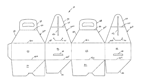
[00036] Referring now to Figure 3 which illustrates a stackable carrier
system 200 that has
been constructed in accordance with the present invention. Carrier system 200
includes, inter
alia, first and second stackable carriers 100a/100b, each of which defines an
interior storage
cavity, for items such as food.
[00037] Each of the carriers 100a/100b is constructed as described with
respect to Figures
2a and 2b. For example, each carrier 100a/100b has opposed end walls 130a/130b
and a first
pair of opposed cover flaps 136 which extend from respective end walls
130a/130b. Each of the
opposed cover flaps 136 define an interlock tab 140. Moreover, each of the
opposed end walls
130a/130b define a reception slot 138 therein. Wherein the interlock tabs 140
defined in each of
the opposed cover flaps 136 of the first carrier 100a are adapted and
configured to interlock with
the reception slots 138 formed in the opposed end walls 130a/130b of the
second carrier 100b
when the second carrier 100b is placed on top of the first carrier body 100a,
as shown in Figure
3.
[00038] It will be recognised that as used herein, directional references
such as "top",
"bottom", "front", "back", "end", "side", "inner", "outer", "upper" and
"lower" do not limit the
-9-
CA 02845446 2014-03-11
respective panels to such orientation, but merely serve to distinguish these
panels from one
another. Any reference to hinged connection should not be construed as
necessarily referring to a
single fold line only; indeed it is envisaged that hinged connection can be
formed from one or
more of the following, a short slit, a frangible line or a fold line without
departing from the scope
of the invention.
[00039] Furthermore, though the invention has been described in the
contact of a
paperboard carrier, in other embodiments of the invention it is envisaged that
other suitable
foldable sheet material may be used for forming the carrier (such as
cardboard, plastics material
and the like).
-10-