Note: Descriptions are shown in the official language in which they were submitted.
CA 02845502 2014-02-14
WO 2013/028246
PCT/US2012/042227
1
ELECTRIC CIGAR LIGHTER,
UNIVERSAL POWER SOCKET AND ACCESSORY PLUG
BACKGROUND OF THE INVENTION
[0001] The present invention relates to electric cigar lighters, for
example, for
automotive vehicles, as well as a universal electrical power socket, for
example, for
vehicles, to allow electrically powered devices to be powered from the
universal
electrical socket. The electrical socket furthermore allows the electric cigar
lighter
of the present invention to be employed therewith. Moreover, the invention
relates
to an accessory electrical plug which can be employed with the universal
electrical
socket.
[0002] Modern vehicles are increasingly being supplied in standard form
without
cigarette/cigar lighters in an effort to reduce the smoking habit.
Furthermore,
modern vehicles are increasingly being suppled with electrical power sockets
for
powering modern electronic devices, for example, chargers for electronic
devices,
computers, video players, and various other forms of electronic equipment.
[0003] In the past, when cigar lighters were standard equipment in
vehicles, the
lighter was plugged into a vehicle electrical socket. The electrical socket
typically
included a bimetallic element which the cigar lighter, when inserted, engaged
to
energize the lighter, and which deenergized the cigar lighter when it reached
operating temperature. By placing the bimetallic element in the socket, the
lighter
could be made simpler, essentially comprising a knob, heating element and
spring
with necessary electrical and thermal insulating elements.
[0004] Now that vehicles are not being supplied with lighters as standard
equipment, the electrical sockets in the vehicles no longer come equipped with
the
bimetallic disengaging elements. Accordingly, the bimetallic elements have
been
CA 02845502 2015-06-25
2
moved to the lighter unit itself. See for example U.S. Patent No. 6,740,850 to
Mattis
and European Patent Application No. 09004224.3 (EP Patent Publication No.
2,233,353).
100051 These designs, however, suffer from disadvantages relating to
achieving
adequate electrical contact at the high currents involved and relating to
providing
adequate thermal protection of the knob and adequate heat transfer to the
bimetallic
element to enable reliable operation.
100061 Furthermore, because the bimetallic element is no longer located in
the
socket, it is desirable to provide an improved electrical socket which
provides
improved electrical contact for powering both lighters as well as portable
electric/electronic equipment but yet which still allows the prior art plugs
employed
with prior art sockets to be used.
100071 Furthermore, it is desirable to provide an improved accessory
electrical
plug which can be plugged into the socket to power electrical/electronic
devices.
SUMMARY OF THE INVENTION
100081 The invention addresses the above problems.
100091 According to one aspect, the invention comprises a cigar lighter
adapted to
be received in an electrical socket for energizing a heating element of the
cigar lighter
comprising an electrically conductive body shell adapted to make electrical
and
mechanical contact with a sleeve of the socket; a user actuatable knob
received in the
body shell for telescopic movement therein against the bias of a compression
spring;
an electrical heating element disposed at a distal end of the body shell, the
electrical
heating element having a first electrical terminal in electrical contact with
a first
electrical contact element disposed around the perimeter of the electrical
heating
element and adapted to make electrical contact with a first electrical contact
of the
electrical socket; the electrical heating element having a second electrical
terminal
substantially centrally located with respect to the body shell, the second
electrical
CA 02845502 2014-02-14
WO 2013/028246
PCT/US2012/042227
3
terminal in electrical contact with a centrally disposed fastener; a first
bimetal
element held in position by the fastener electrically insulated from the body
shell and
being in electrical communication with the second terminal of the heating
element,
the bimetal element including at least two proximally extending engaging
clips; a
movable electrical contact arranged for movement with the user actuatable
knob, the
movable electrical contact being in electrical communication with the body
shell, the
movable electrical contact having first and second positions whereby, in a
first
position, when the knob extends proximally, the movable electrical contact is
not in
electrical engagement with the bimetal engaging clips so that the heating
element is
not energized and wherein, in a second position, when the knob is moved
distally,
the movable electrical contact engages with and is held in position by said
bimetal
engaging clips to energize the heating element with electrical power until a
first
predetermined temperature is reached at which said bimetal clips flex to
release said
movable electrical contact from said bimetal engaging clips to de-energize
said
heating element and allowing said knob to move proximally due to the bias of
said
spring.
[0010] According to another aspect, the invention comprises an electrical
socket
for powering an electrical/electronic accessory device having an electrical
plug that
is received in the socket, comprising an electrically conductive socket well
for
slidably receiving the electrical plug of the electrical/electronic device; an
electrical
connector portion disposed distally on the socket well and comprising an
insulator
fastened to the socket well at a distal end thereof and having at least two
electrical
terminals for connecting to a vehicle electrical power source; a plurality of
first
electrical contacts disposed at a distal end of said socket well and extending
radially
and proximally from the center of said well and being electrically connected
to a first
of said electrical terminals of said electrical connector portion; a second of
said
electrical terminals of said electrical connector portion being electrically
connected
to said socket well; and said plurality of first electrical contacts being
adapted to
CA 02845502 2014-02-14
WO 2013/028246
PCT/US2012/042227
4
electrically slidably engage with an inner periphery of a hollow cylindrical
electrical
contact of said electrical plug.
[0011] According to yet another aspect, the invention comprises an
electrical
accessory plug comprising a plug body having a housing including at least one
spring loaded radially directed electrical contact for slidably electrically
engaging
with an electrically conductive well of an electrical socket; and a distally
disposed
contact insulated from said housing and comprising an electrically conductive
cylinder adapted to make sliding contact on an inner peripheral surface
thereof with a
radially directed contact disposed in insulated fashion in the well of said
electrical
socket.
[0012] According to another aspect, the invention comprises a heating
assembly
for a cigar lighter comprising a cylindrical body having an electrical heating
element
having a first electrical terminal in electrical contact with the cylindrical
body, the
cylindrical body being disposed around the perimeter of the electrical heating
element and adapted to make electrical contact with a first electrical contact
of an
electrical socket; the electrical heating element having a second electrical
terminal
substantially centrally located with respect to the cylindrical body, the
second
electrical terminal in electrical contact with a centrally disposed fastener;
further
wherein the heating element is in the shape of a spiral having the first
electrical
terminal disposed on the outside of said spiral, said first electrical
terminal being
received through a slot in said cylindrical body thereby_electrically engaging
with
said cylindrical body, the second electrical terminal being disposed at the
inside of
said spiral and being in electrical engagement with said centrally disposed
fastener,
further comprising a concentric cap disposed outside said cylindrical body
surrounding at least a part of said cylindrical body and fixing said first
electrical
terminal of said heating element between said cap and an outer periphery of
said
cylindrical body.
CA 02845502 2014-02-14
WO 2013/028246
PCT/US2012/042227
[0013] According to still another aspect, the invention comprises a cigar
lighter
adapted to be received in an electrical socket for energizing a heating
element of the
cigar lighter, comprising an electrically conductive body shell adapted to
make
electrical and mechanical contact with a sleeve of the socket; a user
actuatable knob
attached to the body shell for movement against the bias of a compression
spring; an
electrical heating element disposed at a distal end of the body shell, the
electrical
heating element having a first electrical terminal in electrical contact with
a first
electrical contact element disposed around the perimeter of the electrical
heating
element and adapted to make electrical contact with a first electrical contact
of the
electrical socket, the electrical heating element being controlled to reach a
first
predetermined temperature to allow ignition of a cigar or cigarette; the
electrical
heating element having a second electrical terminal substantially centrally
located
with respect to the body shell, the second electrical terminal in electrical
contact with
a centrally disposed fastener; further comprising a thermal protection bimetal
element in electrical communication with said first electrical contact element
for
electrically contacting either said body shell or a part in electrical
communication
with said body shell in the event the temperature of said heating element
reaches a
second predefined temperature higher than said first predetermined temperature
to
avert a safety hazard.
[0014] According to still yet another aspect, the invention comprises a
cigar
lighter adapted to be received in an electrical socket for energizing a
heating element
of the cigar lighter, comprising an electrically conductive body shell adapted
to make
electrical and mechanical contact with a sleeve of the socket; a user
actuatable knob
received in the body shell for telescopic movement therein against the bias of
a
compression spring; an electrical heating element disposed at a distal end of
the body
shell, the electrical heating element having a first electrical terminal in
electrical
contact with a first electrical contact element disposed around the perimeter
of the
electrical heating element and adapted to make electrical contact with a first
electrical contact of the electrical socket; the electrical heating element
having a
CA 02845502 2014-02-14
WO 2013/028246
PCT/US2012/042227
6
second electrical terminal substantially centrally located with respect to the
body
shell, the second electrical terminal in electrical contact with a centrally
disposed
fastener; a first bimetal element held in position by the fastener
electrically insulated
from the body shell and_being in electrical communication with the second
terminal
of the heating element, the bimetal element having a proximally extending
engaging
element; a movable electrical contact arranged for movement with the user
actuatable knob, the movable electrical contact being in electrical
communication
with the body shell, the movable electrical contact having first and second
positions
whereby, in a first position, when the knob extends proximally, the movable
electrical contact is not in electrical engagement with the bimetal engaging
element
so that the heating element is not energized and wherein, in a second
position, when
the knob is moved distally, the movable electrical contact engages with and is
held in
position by said bimetal engaging element to energize the heating element with
electrical power until a first predetermined temperature is reached at which
said
bimetal engaging element flexes to release said movable electrical contact
from said
bimetal engaging element to de-energize said heating element and allowing said
knob to move proximally due to the bias of said spring, further wherein said
movable
electrical contact can be held in electrical engagement with a proximally
directed
head of said centrally disposed fastener by pressing said user actuatable knob
distally
to maintain electrical current flow to said heating element even if said first
bimetal
element has released the movable electrical contact.
[0015] According to yet still another embodiment, the invention comprises a
cigar lighter adapted to be received in an electrical socket for energizing a
heating
element of the cigar lighter, comprising an electrically conductive body shell
adapted
to make electrical and mechanical contact with a sleeve of the socket; a user
actuatable knob attached to the body shell for movement against the bias of a
compression spring; an electrical heating element disposed at a distal end of
the body
shell, the electrical heating element having a first electrical terminal in
electrical
contact with a first electrical contact element disposed around the perimeter
of the
CA 02845502 2014-02-14
WO 2013/028246
PCT/US2012/042227
7
electrical heating element and adapted to make electrical_contact with a first
electrical contact of the electrical socket; the electrical heating element
having a
second electrical terminal substantially centrally located with respect to the
body
shell, the second electrical terminal in electrical contact with a centrally
disposed
fastener; further wherein the first electrical contact element comprises a
cylindrical
contact element surrounding the electrical heating element; further wherein
the
heating element is in the shape of a spiral having the first electrical
terminal disposed
on the outside of said spiral, further wherein the first electrical terminal
of the
heating element is secured electrically and mechanically to a coil retainer
that
surrounds the heating element; wherein the coil retainer is rolled over to
secure the
first electrical terminal in a region of the perimeter of the coil retainer
comprising
only a portion of the perimeter of the coil retainer.
BRIEF DESCRIPTION OF THE DRAWING(S)
[0016] The invention will be described in greater detail in the following
detailed
description with reference to the drawings in which:
[0017] Figure 1 shows a cut-away view of a first embodiment of the cigar
lighter
according to the present invention inserted into an electrical socket, with
the cigar
lighter in a stand-by, deenergized position;
[0018] Figure 1A shows the lighter of Figure 1 in its socket in the
energized
position in a view rotated 90 Figure 1;
[0019] Figure 1B shows details of the socket, including the B+ contact
(power)
spring in a view rotated 180 from Figure 1A;
[0020] Figure 2 shows a cut-away view of the cigar lighter in the stand-by
position (socket not shown);
[0021] Figure 3 shows a cut-away view the cigar lighter in the energized
position
(socket not shown);
CA 02845502 2014-02-14
WO 2013/028246
PCT/US2012/042227
8
[0022] Figure 3A shows the cigar lighter of Figure 3 when the "relite"
feature is
being employed;
[0023] Figure 4 shows a perspective view of a second embodiment of the
cigar
lighter;
[0024] Figure 5 shows the second embodiment of the cigar lighter in a cut-
away
view (socket not shown);
[0025] Figure 5A shows the second embodiment of the cigar lighter in its
energized or powered-on position (socket not shown);
[0026] Figure 6 shows the heating element assembly of the second embodiment
in a perspective view;
[0027] Figure 7 shows a bottom perspective view of the heating element
assembly;
[0028] Figure 8 shows a portion of the heating element assembly showing
details
of the heating coil retainer/contact;
[0029] Figure 9 shows a cigar lighter according to the invention employing
an
alternative embodiment of the heating element assembly and coil retainer;
[0030] Figure 9A shows details of the embodiment of Figure 9;
[0031] Figure 9AA shows a modified embodiment of Figure 9;
[0032] Figures 9B-9K show details of the assembly process for the
embodiment
of Figure 9;
[0033] Figure 10 shows a cigar lighter according to the invention employing
another alternative embodiment of the heating element assembly and coil
retainer;
[0034] Figure 10A shows details of the embodiment of Figure 10;
CA 02845502 2014-02-14
WO 2013/028246
PCT/US2012/042227
9
[0035] Figure 10AA shows details of Figure 10A.
[0036] Figures 10B-10H show details of the assembly process for the
embodiment of Fig. 10;
[0037] Figure 11 shows the heating element assembly of Figure 8 and showing
one form of a thermal protection element;
[0038] Figure 12 shows the heating element assembly of Figure 8 showing an
alternative embodiment of the thermal protection element;
[0039] Figure 13 shows yet another alternative embodiment of the thermal
protection element;
[0040] Figure 13A shows another alternative embodiment of the thermal
protection element;
[0041] Figure 13B shows the bimetal thermal protection disc of Figure 13A.
[0042] Figure 13C shows the heating element and unactivated bimetal thermal
protection disc;
[0043] Figure 13D is a cross section along line A-A of Figure 13C;
[0044] Figure 13E shows the heating element with the bimetal thermal
protection
disc in an activated state;
[0045] Figure 13F is a cross section along line B-B through a center plane
of the
heating element of Fig. 13E.
[0046] Figure 14 shows a cut-away view of the universal socket according to
the
invention;
[0047] Figure 15 shows the contact assembly of the universal socket in a
bottom
view;
CA 02845502 2014-02-14
WO 2013/028246
PCT/US2012/042227
[0048] Figure 16 shows a top perspective view of the contact plate for the
universal socket;
[0049] Figure 17 shows a bottom view of the contact plate;
[0050] Figure 18 shows the upper insulator of the contact assembly in a top
perspective view;
[0051] Figure 19 shows the upper insulator in a bottom view;
[0052] Figure 20 shows the lower insulator of the contact assembly in a top
view;
[0053] Figure 21 shows the lower insulator from below;
[0054] Figure 22 shows a bottom perspective exploded view of the contact
assembly;
[0055] Figure 23 shows the assembled contact assembly in a bottom
perspective
view;
[0056] Figures 24 and 25 show two different side views, turned 90 , of an
alternative embodiment of the contact assembly;
[0057] Figure 26 shows a perspective view of the alternative contact
assembly;
[0058] Figures 27 and 28 show top and bottom views, respectively, of the
alternative embodiment of the contact assembly;
[0059] Figures 29, 30 and 31 show yet a further contact assembly in side
and top
perspective views;
[0060] Figures 32, 33, 33A, 34, 34A and 34B show various views of yet still
a
further contact assembly;
CA 02845502 2014-02-14
WO 2013/028246
PCT/US2012/042227
11
[0061] Figure 35 shows yet still a further embodiment of the socket in a
cut away
side view showing yet another contact assembly;
[0062] Figure 36 shows the embodiment of Figure 35 from the side;
[0063] Figure 37 shows a prior art electrical plug for use with known
vehicle
electrical power outlets;
[0064] Figure 38 shows how the prior art plug is received in the universal
socket
according to the present invention;
[0065] Figure 39 shows an electrical accessory device plug according to the
invention inserted in the universal socket according to the present invention;
and
[0066] Figures 40 and 41 show how the inventive electric cigar lighter of
the
second embodiment can be received in the universal socket according to the
present
invention, with Figure 40 showing the cigar lighter in the stand-by position
and
Figure 41 showing it in the powered-on position.
DETAILED DESCRIPTION OF EMBODIMENTS OF THE INVENTION
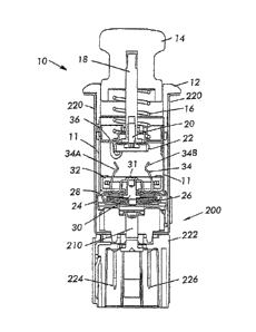
[0067] With reference now to the drawings, Figure 1 shows one embodiment of
an electric cigar lighter 10 in accordance with the present invention received
in a
known vehicle electrical socket 200. The cigar lighter 10 is shown in Figure 1
in its
stand-by or deenergized position. Figure 2 shows the cigar lighter in the
stand-by
position but not in its socket. Figure 3 shows the cigar lighter in its
energized
position, but not in the socket.
[0068] The cigar lighter 10 comprises a cylindrical shell 11 that is made
of
metal, for example, steel plated to inhibit corrosion. The shell 11 is
attached to a
ring shaped knob escutcheon 12. A center knob part 14 is received in the
escutcheon
12 for slidable movement therein against the opposition of a coil spring 16.
The
CA 02845502 2014-02-14
WO 2013/028246
PCT/US2012/042227
12
knob 14 is mounted concentrically on a metal shaft 18. The knob 14 and
escutcheon
12 are typically made of a plastic material.
[0069] At the distal end of the shaft 18, a screw 20 is provided. The screw
20
retains an annular electrical contact 22 to the shaft 18.
[0070] At the base or distal-most end of the cigar lighter 10, there is
provided
formed into the cylindrical shell 11 an enlarged region 24. In the enlarged
region 24,
an electrical heating assembly including a heating element 26 is provided. The
electrical heating element assembly has a contact/shield 28 surrounding the
heating
element 26. The heating element 26 is typically made of a resistance material
such
as nichrome wire or banding that is formed in a spiral shape having an outer
portion
of the winding secured to the shield 28 which functions as an electrical
contact. The
inner-most end of the heating element 26 is connected to a contact rivet 30
which is
mounted in an electrical and thermal insulator 32, for example, made of
ceramic.
Connected electrically to the rivet 30 and thus to the heating element is a
bimetallic
element 34 mounted on insulator 32 that is formed in the shape of a clip
having two
opposed members 34A and 34B. The bimetallic element is provided as part of a
switch in the lighter that allows energization of the heating element 26 until
the
heating element reaches an operating temperature, at which point the
bimetallic
element flexes outwardly and disengages from contact 22 as will now be
explained,
to deenergize the heating element 26.
[0071] Figure 2 shows the cigar lighter in its deenergized position. Figure
1
shows the cigar lighter engaged in the socket but in a deenergized state
because the
bimetallic clip element 34 is not in electrical contact with the contact 22.
[0072] With reference to Figures 1, 1A and 1B, at the distal end of socket
200,
an electrical insulator 222 is provided, made of molded plastic, typically,
which
includes two electrical terminals 224 and 226 for receiving electrical power
from the
vehicle electrical power source. One of these terminals 224 is coupled to the
center
rivet 210 of the socket 200 and the other is coupled to the socket shell 220.
CA 02845502 2014-02-14
WO 2013/028246
PCT/US2012/042227
13
[0073] When lighter 10 is inserted in socket 200, the enlarged area 24 of
cylindrical shell 11 engages spherical feature 229 of retention lances 228 as
shown in
Figure 1B. This engagement retains lighter 10 in proper position within socket
200.
The invention places the retention lances 228 in a location that will not be
distorted
when accessory male plugs are inserted into socket 200, unlike traditional
cigar
lighters where the retention lances were placed closer to the opening of the
metal
socket shell 220. This provides protection to the retention lances from
external
forces.
[0074] To energize the heating unit, the knob 14 is placed into the
position
shown in Figure 3, that is, it is pressed into the annular escutcheon element
12
against the bias of the compression spring 16. The annular contact 22 is
received
between the two opposed ends 34A and 34B of the bimetallic element 34 as shown
in Figure 3. Thus there is electrical contact between contact 22 and
bimetallic
element 34. This completes an electrical circuit from the socket. In
particular, when
the lighter unit 10 is inserted in the socket 200 and the knob 14 is in the
pushed-in
position as shown in Figure 3, it places the lighter unit in the electrically
energized
condition. Electrical current flows from the vehicle positive supply (positive
current
convention is used herein) connected to terminal 224 (Figure 1) coupled to
socket
rivet 210 which is electrically coupled to socket terminal 227 as shown in
Figures 1A
and 1B. The shield 28 is electrically and mechanically engaged with terminal
227
when knob 14 is in the pushed-in position. Current flows through the coiled
heating
element 26 to heat up the heating element 26 and then to the center rivet 30
to the
bimetallic element 34 which is engaged electrically and mechanically with the
contact 22. The electrical circuit is completed through shaft 18 and a
conductive
element 36 to the external lighter shell 11, which is coupled electrically to
the metal
socket shell 220 and hence to the vehicle ground return via terminal 226.
[0075] When the heating element 26 reaches operating temperature, heat that
is
convected/radiated/conducted to the bimetallic element 34 causes the
bimetallic
element ends 34A and 34B to flex outwardly, thereby allowing the contact 22 to
CA 02845502 2014-02-14
WO 2013/028246
PCT/US2012/042227
14
move out of engagement therewith and move upwardly away from the bimetallic
element 34 by virtue of the force provided by the compression spring 16. This
breaks the electric circuit and the heating element 26 is no longer energized
but can
be removed from socket 200 to be utilized to light a cigarette or cigar.
[0076] The invention places the bimetallic switch contact 34 within the
cigar
lighter, unlike traditional cigar lighters where the bimetallic element was
placed in
the socket 200. This provides protection to the bimetallic contact from
external
forces.
[0077] The proximity of the bimetallic contact 34 to the heating element 26
provides for improved heat transfer resulting in improved control of the
heating
element temperature by conductive and convective means. The placement of the
switch contact 22 in connection with the shaft 18 connected to the actuating
knob 14
provides for lower surface temperature of the knob 14.
[0078] The contact 22 also contains a feature, called a "relite" feature,
to allow
for continuous electrical power to the lighter unit when the bimetallic
contact 34 is
flexed outwardly from heat transfer. Specifically, if a user desires to keep
the
heating element energized even after the bimetallic element has deflected
outwardly
to cause the heating element to be deenergized, the user can push the knob 14
back
into the knob escutcheon 12 and hold the knob 14 depressed to maintain the
heating
element 26 in the energized position. The heating element 26 will then
continue to
be energized, not through electrical contact between the contact 22 and the
bimetallic
element 34, but by electrical contact between the head 37 of the screw 20 and
the top
31 of the center rivet 30 as shown in Fig. 3A. This will ensure electrical
continuity
between the ground side of the heating element 26 and the head 37 of the screw
20
and therefore to the shell 11 and thus to the socket shell 220.
[0079] As will be explained in more detail below, should the temperature
inside
the lighter unit increase beyond a safe temperature, particularly if this
feature to keep
the heating element 26 energized is over-used, there is a feature provided in
the
CA 02845502 2014-02-14
WO 2013/028246
PCT/US2012/042227
lighter unit 10 to provide an electrical short circuit to blow a fuse in the
electrical
circuit providing power to the cigar lighter socket 200 thereby to prevent the
risk of
fire hazard or melting of the cigar lighter components in the socket or the
wiring to
the socket.
[0080] Figure 4 shows a second embodiment of the cigar lighter in a
perspective
view. The second embodiment comprises a two-part knob comprising a push in
part
14A and collar 14B and a cylindrical shell 11A which is received in a new
socket
(shown in Fig. 14) to be described herein.
[0081] Turning to Figure 5, the cigar lighter of Figure 4 is shown in a cut-
away
view in a deenergized position. The knob 14 comprises a telescoping knob part
14B
received in outer part 14A and which is actuated by a user and is held in the
position
shown in Figure 5 against the bias of a coil spring 16.
[0082] The cigar lighter of Figure 5 includes a bimetallic element 34,
shaft 18
and contact 22. Shaft 18 and contact 22 are in electrical contact with portion
36
which is in sliding electrical contact with the outer shell 11A.
[0083] At the distal end of the cigar lighter, there is provided an
electrically
conductive cylindrical metal contact/coil retainer 28A. The contact 28A is
received
in a cap 29. The heating element 26 is in the shape of a spiral as in the
embodiment
of Figure 1 and has its outer periphery in electrical contact, as will be
explained
below, with the contact 28A. The cap 29 is also made of a conductive material
such
as metal.
[0084] Figure 6 shows the heating element assembly in a perspective view
showing the bimetallic contact 34 which is received on an insulator 35. The
insulator 35 is located concentrically in a ground retainer 38 which is in
contact with
the outer shell 11A. The ground retainer 38 is insulated from the bimetallic
contact
34 and the central rivet 30 and also from cap 29 by an insulator 40 (Fig. 5).
CA 02845502 2014-02-14
WO 2013/028246
PCT/US2012/042227
16
[0085] Figure 7 shows a bottom perspective view of the heating element
assembly showing the ground retainer 38, the cylindrical contact 28A and the
cap 29.
There is an insulator 40 disposed between the ground retainer 38 and the cap
29.
Disposed above the cap 29 is furthermore a thermal bimetallic protector 41,
which is
designed to protect the electric cigar lighter from overheating, as will be
explained
below.
[0086] As shown in Figures 7 and 8, the heating element 26 is spirally
wound
and has an outside end 26A that is received between the contact 28A and the
cap 29.
The external end or tail 26A of the heating element 26 is captured in a
circumferential groove 42 that is provided in the contact 28A, as shown in
Figure 8.
The tail 26A is captured between the contact 28A and the cap 29, securely held
in
position and making electrical contact with the contact 28A. The tail 26A is
received
in the circumferential groove 42 through a slot 44 provided in the contact
28A, as
shown in Figure 8. Cap 29 is also preferably provided with an aligned groove
43 in
Figure 6 to securely capture the tail 26A and ensure good electrical contact.
[0087] The inner end of the heating element 26 is securely fitted in a slot
30A
provided in the end of the center rivet 30 in the center of the heating
element
assembly, as shown in Figure 7, for example, by swaging.
[0088] Figure 5A shows the cigar lighter in the energized condition.
Electrical
current flows from cylindrical contact 28A through heating element 26, to
rivet 30 to
clip 34 thence to annular contact 22 to shaft 18 and then through member 36 to
shell
wall 11A and thence to the socket wall to the ground return. When bimetallic
contact 34 has reached a predetermined temperature corresponding to an
adequate
temperature to allow ignition of a cigar, the ends of clip 34 flex outwardly
enough to
interrupt the circuit and spring 16 retracts annular contact 22.
[0089] As described above, there is also a bimetal thermal protector 41 as
shown
in Figures 5, 6 and 7, that flexes outwardly in the event the temperature in
the
heating element assembly exceeds a predefined safe temperature due to
overheating
CA 02845502 2014-02-14
WO 2013/028246
PCT/US2012/042227
17
of the heating element 26. If this occurs, the bimetal thermal protector 41
flexes
radially outwardly, making contact with the external shell 11A, causing a
short
circuit to ground and blowing a fuse in the supply line to the socket, thereby
deenergizing heating element 26 and preventing the risk of fire hazard.
Protector 41
is in electrical contact with the cap 29 and contact 28A.
[0090] Figure 9 shows the cigar lighter according to the present invention
utilizing an alternative embodiment of the coil retainer. In this embodiment,
a full
rollover coil retainer is used.
[0091] This coil retainer design is similar to disclosures contained in
U.S. Patent
Nos. 4,007,353 and 4,045,865.
[0092] In particular, the embodiment of the cigar lighter in Figure 9 is
show
inserted in its socket. In particular, the differences in this embodiment
relate to how
the heating element 26 is retained in the coil retainer.
[0093] In the embodiment shown in Figure 9, a full rollover coil retainer
27 is
employed. Details are shown in Figure 9A. In the embodiment shown in Figure 9,
the coil retainer cap 28AA also functions as the positive side contact for the
cigar
lighter, similarly to the contact 28A of Figure 5. The coil retainer cap 28AA
is
stepped down as shown at 28AAA. In the embodiment shown in Figure 9A, the coil
retainer cap 28A is not stepped down, however, a circumferential bead 28AAAA
provides retention of the full rollover coil retainer 27 to the coil retainer
cap 28A,
28AA.
[0094] Another embodiment replaces the circumferential bead 28AAAA with
localized multiple dimples 28ABA (See Figure 9AA).
[0095] In this embodiment of the heating element assembly, the heating
element
26 is held in position by a rolled over coil retainer 27. This is shown in
more detail
in Figure 9A. In particular, the heating element tail 26A, as shown in Figures
9A
CA 02845502 2014-02-14
WO 2013/028246
PCT/US2012/042227
18
and 9B is received in the coil retainer 27 during the manufacturing process.
The
heating element 26 is inserted into the coil retainer 27 and during the
manufacturing
process, the edge is rolled over as shown in Figure 9C to retain the tail 26A
of the
heating element and thereby provide a secure electrical and mechanical
connection.
Figure 9D shows how the heating element tail 26A is captured when the coil
retainer
27 is rolled over around it. The embodiment of Figure 9 has what is called a
full
rollover coil retainer because the coil retainer is rolled over along the
entire
circumference of the coil retainer.
[0096] Figure 9E through 91 show further details of the manufacturing
process.
After the rollover of the edge of the coil retainer 27, the rivet 30 is
inserted as shown
in Figures 9E and 9F. The center terminal 26B of the heating element is
swedged to
the slot 30A of the rivet 30 to securely fasten it mechanically and
electrically to the
rivet 30. Figure 9F shows the rivet assembled to the heating element 26 and
coil
retainer 27. Then, as shown in Figure 9G, the coil retainer cap 28A, which
functions
as the positive side electrical contact to the socket, is assembled to the
rivet with an
insulator 37 provided between the coil retainer cap 28A and the shoulder 30B
of the
rivet 30. Electrical insulation must be provided between the coil retainer cap
28A
which functions as the positive side contact and which is electrically engaged
to the
coil retainer 27.
[0097] Figure 9H shows the alternative embodiment with the step down
diameter
coil retainer cap 28AA showing the step down at 28AAA. Figure 91 shows the
step
down embodiment in a cross section.
[0098] Figures 9J and 9K show alternative ways of insuring that the coil
retainer
27 is securely held in the coil retainer cap contact 28A. In one embodiment,
three
localized snap tabs 35A are provided, as shown in Figure 9J, angularly spaced
about
the coil retainer cap 28A. For example, they may be equiangularly spaced.
Although three tabs are shown, a lesser or greater number can be used.
CA 02845502 2014-02-14
WO 2013/028246
PCT/US2012/042227
19
[0099] Figure 9K shows another embodiment showing bent tabs 35B. A
plurality of these can be used angularly spaced about the coil retainer cap
28A. A
lesser or greater number can be used.
[00100] Figure 10 shows another embodiment of the heating element assembly in
the cigar lighter according to the present invention (shown in the socket). In
this
embodiment, a partial rollover coil retainer 27A is utilized. In this
embodiment,
shown in greater detail in Figures 10A and 10AA, the coil retainer 27A
utilizes a
rollover only in a certain angular region of the perimeter of the coil
retainer 27A to
secure the tail 26A of the heating element 26. In this embodiment, shown more
particularly in Figure 10AA, and even more particularly in Figures 10B-10D,
the
heating element 26, as shown in Figure 10B is attached to the rivet 30. As
shown in
Figure 10D, the tail 26A of the heating element is then inserted into a coil
retainer
28AB which functions as an integral coil retainer and cigar lighter positive
side
contact. The heating element 26 is aligned with a partial rollover region 27A
or
inserted into the partial rollover region 27A which is then crimped to provide
the
secure electrical contact to the tail 26A of the heating element 26. Thus, in
this
embodiment, it is not necessary to roll over or crimp the entire coil retainer
27. As
noted, in this embodiment, the coil retainer 27 and the contact 28AB form a
single
integral component. Then, as shown in Figure 10F, the heating element assembly
comprising the heating element 26 held in the coil retainer 28AB and fastened
to the
rivet 30 is attached to the coil retainer cap 29 with rivet 30 with an
insulator 37
therebetween, as in the embodiment of Figure 9. Then, to insure engagement
between the cap 29 and the coil retainer 28AB, a bead 42 is rolled in the cap
29 to
securely engage the cap 29 to the coil retainer 28AB. See Figures 10G and 10H.
[00101] Figure 11 shows a further embodiment of the thermal protection bimetal
contact, here identified by 41A.
[00102] In Figure 11, the bimetal 41A is pointed upwardly towards the knob 14.
Should the operating temperature increase to an unsafe temperature, the
bimetal 41A
CA 02845502 2014-02-14
WO 2013/028246
PCT/US2012/042227
flexes radially outwardly and makes electrical contact with the ground
retainer 38
causing a short circuit to remove power to the cigar lighter and thus prevent
a fire
hazard.
[00103] In an alternative embodiment, shown in Figure 12, the thermal
protection
bimetal is shown at 41B. In this embodiment, the bimetal 41B is U shaped in
cross
section as shown in Figure 12 and is designed to flex outward and make contact
with
the ground retainer 38 thereby to provide a short circuit to blow the fuse and
remove
the electrical supply to the cigar lighter.
[00104] Note that in Figures 11 and 12, the contact 28A is used. However, the
contact/shield 28 of Figures 1 to 3 could also be employed.
[00105] A more detailed view of the thermal protection bimetal used in Figure
5 is
shown in Figure 13. In this embodiment, the bimetal 41 points distally and
flexes
outwardly to electrically engage the outer shell 11A to cause a short circuit
in the
event of an overcurrent, blowing the fuse supplying electrical power to the
cigar
lighter to prevent a fire hazard.
[00106] Figure 13A shows an alternative and presently preferred embodiment of
the thermal protection bimetal element. As in the other embodiments, this
element
relates to a means that provides thermal protection from excessive heat
transfer from
the heating element and is located within the heating unit as compared to
placement
within the socket.
[00107] With reference to Figure 13A, a circular bimetallic disc 41C
consisting of
cutouts 41CC that create one or more activation beams 41D is placed in
intimate
contact with the coil retainer cap 29. Locking holes 41E are positioned
asymmetrically in alignment with locking pins 35A of ceramic insulator 35 to
insure
the proper orientation of the low expansion side of the bimetallic disc 41C.
Improper
orientation will result in lack of concentricity of the disc to the
circumference of coil
retainer cap 29 and thus problems with assembly into subsequent assembly
levels.
CA 02845502 2014-02-14
WO 2013/028246
PCT/US2012/042227
21
This lack of concentricity will be obvious during assembly and thus will
prevent
such improper assembly.
[00108] An insulating isolation disc 40A, with corresponding cutouts 40B that
allow the bimetallic cantilever beam(s) 41D to deflect and having locking
holes 40E
is aligned to the thermal protection bimetallic disc 41C allowing the
activation beam
41D to deflect and short to the ground retainer 38 upon exposure to excessive
heat.
[00109] The isolation disc 40A provides electrical isolation and the means
to
control the gap between the bimetallic disc 41C and the ground retainer 38, a
distance that effectively determines the temperature of the heating element at
which
the bimetallic disc will short to ground and the current will increase until
the in-line
fuse will open.
[00110] The embodiment of Figures 13A-F introduces a simple and precise way
to control the gap through which the bimetallic beam 41D will travel to short
to
ground the electrical circuit. The prior art provides for two or more
dimensional
features, with associated tolerances to control this gap. This method requires
only
one feature to accomplish the establishment of the gap.
[00111] Unlike the prior art, this embodiment maintains a uniform temperature
of
the bimetallic disc 41C that changes in temperature correspondingly while the
coil
retainer cap 29 increases in temperature. The prior art results in sections of
the
bimetallic member cooling by convection heat transfer resulting in a thermal
gradient
across the bimetallic member prior to the deflection of the member due to the
presence of elevated temperature. This can cause an unreliable actuation.
[00112] The positioning of the asymmetrical locking holes in the coil retainer
cap
29 (29E), in the thermal protection disc 41C (41E), in the isolation disc 40A
(40E)
and in the ground retainer 38 (38E) that align with asymmetrical locking pins
35A in
the insulator 35 provides visual verification for the orientation of the
bimetal disc
41C low expansion side. Should the bimetal disc's low expansion side be
CA 02845502 2014-02-14
WO 2013/028246
PCT/US2012/042227
22
improperly oriented, then the circumference of the disc would project beyond
the
envelope of the coil retainer cap's circumference which in turn will prevent
the
subsequent assembly in the ash guard. Thus, it will be obvious if the disc 41C
is
improperly oriented, i.e., the high thermal expansion side pointing up instead
of
down.
[00113] In contrast to the cigar lighter embodiment of Figure 1, the
embodiment
of Figure 5 employs a new form of the positive supply side cigar lighter
electrical
contact, that is, the cylindrical contact 28A. In the embodiment of Figure 1,
the
positive side contact is of the conventional type, i.e., the contact/shield
member 28
which contacts the socket positive contact. In contrast to this conventional
design, in
the embodiment shown in Figure 5, the new design contact 28A is of a
cylindrical
design, that makes contact with a new and improved socket contact which will
be
described later herein. The new contact 28A provides an improvement in current
handling capability by providing a stable and low contact resistance
electrical
connection between the contact 28A and the heating element 26 and also by
providing a shelf cleaning (sliding contact) capability to minimize electrical
arcing
with the socket contact.
[00114] The electric cigar lighter disclosed herein provides for a means to
switch
the cigar lighter on that is protected from external forces because the
bimetal element
34 is placed within the lighter unit in comparison to prior art designs where
it is
placed in the socket.
[00115] The electric cigar lighter according to the invention provides for
improved thermal control of the heating element by placing the bimetallic
element
34 in close proximity to the heating element and allowing heat transfer from
the
heating element to the bimetallic element by conduction, conduction and
radiation.
[00116] The electric cigar lighter according to the present invention
provides for a
continuous power feature that allows for continuous electrical current flow
after the
bimetallic contact 34 separates from the contact 22, interrupting the current
flow, to
CA 02845502 2014-02-14
WO 2013/028246
PCT/US2012/042227
23
allow for continuous heat supply but yet ensuring proper thermal protection of
the
cigar lighter. This feature is activated when the actuating knob 14 is
depressed
continuously, allowing the head of screw 20 to contact head 31 of rivet 30.
[00117] The cigar lighter cylindrical electrical contact 28A allows
electrical
contact from the socket to be made on the inner diameter of the contact
element 28A.
This provides an ability for a shelf cleaning sliding action that reduces
potential
detrimental effects of electrical arcing found in prior art designs. In order
to
accomplish this, a new design socket contact, to be described below, is used.
[00118] The electrical cigar lighter provides for a stable electrical
contact
including low contact resistance between the heating element 26 and the coil
retainer/contact 28A. Furthermore, the new design contact 28A functions as a
passive, non moving ash guard that eliminates all associated functional
problems
with moving parts in prior art ash guard designs.
[00119] Furthermore, the cigar lighter of the present invention provides
for
thermal protection of the cigar lighter heating unit and socket by placing the
thermal
protection bimetal device within the lighter unit itself The cigar lighter
according to
the invention achieves a commercial advantage by disposing the thermal
protection
device within the lighter unit as opposed to the conventional placement in the
socket.
Thermal protection is required in order to remove electrical power to the
heating
element upon reaching a prescribed temperature to prevent a safety hazard.
Placing
the thermal protection element within the heating unit allows the original
equipment
manufacturer to provide a universal power socket that does not have the added
cost
associated with thermal protection.
[00120] Figure 14 shows a universal power socket which can be employed to
provide power to the cigar lighter shown in Figure 5 as well as to other
electrical
accessory devices, for example, electrical chargers, laptop computers, etc.
CA 02845502 2015-06-25
24
[00121] In the
past, vehicle electrical power sockets have been of several designs.
In one design, a bimetallic element is provided in the socket for use with a
cigar
lighter intended to be inserted into the socket. In another design, the socket
does not
include a bimetallic element. Instead, a centrally located positive side
vehicle
electrical supply connection is provided that is adapted to contact a spring
loaded
contact on an electrical plug. In another design adapted to be used with cigar
lighters
where the bimetallic element is built into the cigar lighter, a positive side
supply
socket contact engages with the lighter positive side supply contact. See U.S.
6,740,850 or EP 09004224.3 (EP Patent Publication No. 2,233,353). In all of
these
designs, the ground connection is provided by the shell of the socket.
[00122] The problem with these designs is that inadequate contact may be made
with the central or positive contact. Often, the prior art plugs that are
employed with
these sockets have a spring loaded center contact that engages with the center
contact
of the socket through the action of the spring force to maintain electrical
connection.
Similarly, the lighter of the above two patent documents relies on spring
contacts for
the positive side electrical contact. However, these can provide an inadequate
electrical contact.
[00123] An example of the prior art electrical accessory plug 300 is shown in
Figure 37. This design employs a spring loaded curved ground contact 310 for
making electrical contact with the shell of the socket. A center spring loaded
positive
contact 320 is provided for making contact with the positive side socket
contact.
Often the positive contact arcs when the electrical contact is first made or
when it is
removed, resulting in damage to the contact which causes higher resistance
electrical
connections to be formed. The socket of the present invention eliminates these
effects.
[00124] At the same time, the socket according to the present invention is a
universal socket because it can also be employed with the prior art accessory
plug 300
shown in Figure 37..
CA 02845502 2014-02-14
WO 2013/028246
PCT/US2012/042227
[00125] Turning to Figure 14, the power socket according to the present
invention
is shown. In this embodiment, the socket comprises a socket well 400 and an
electrical connector portion 405 comprising an insulating body 410 provided
with
electrical terminals 412 (Fig. 36) and 414 for connection to the vehicle
electrical
supply. Terminal 414 is electrically connected to a central rivet 416. The
rivet 416
holds an upper insulator 418 concentrically in the socket shell 400. The rivet
is thus
insulated from shell 400. In electrical connection with the rivet 416 and
clamped
between the insulator 418 and an additional lower insulator 420, is an
electrical
contact plate 422. The electrical contact plate 422 includes a plurality of
radially and
proximally directed contact elements 422A as shown in Figures 16 and 17. The
lower insulator 420 insulates contact plate 422 from the shell 400.
[00126] Turning to Figure 16, the electrical contact plate 422 is shown. It
has a
plurality, in the embodiment shown, three, sliding spring loaded electrical
contacts
422A which have contact buttons directed radially outwardly. These contact
buttons
422A are designed to make electrical contact with the inside surface of coil
retainer/contact element 28A of the cigar lighter of Figure 5 and also to an
accessory
plug to be described hereinafter which can be employed to provide electrical
power
to electrical/electronic accessory devices that are used in a motor vehicle.
Figure 16
shows the electrical contact plate in a top perspective view. Figure 17 shows
the
electrical contact plate 422 in a bottom perspective view. The electrical
contact plate
422 is held in position by the rivet 416 which extends through a central
opening 423
of the contact element. The central opening 423 has gripping surfaces 421 for
ensuring good electrical contact to rivet 416.
[00127] Figures 18 and 19 show top and bottom perspective views of the upper
insulator 418.
[00128] The upper insulator 418 may include a plurality of alignment recesses
424. The upper insulator 418 and lower insulator 420 provide electrical
isolation of
the contact plate 422 and rivet 416 from the socket well 400.
CA 02845502 2014-02-14
WO 2013/028246
PCT/US2012/042227
26
[00129] The lower insulator 420 is shown in Figures 20 and 21 in top and
bottom
views respectively. The lower insulator may include a plurality of alignment
projections 425 which are received in the alignment recesses 424 of the upper
insulator 418. The lower insulator 420 provides for electrical isolation of
the rivet
416 and contact plate 422 from the well 400. The alignment projections 425
provide
for indexing to the contact plate 422 and the upper insulator 418. The lower
insulator 420 includes a pilot shoulder 426 that has an inner and outer
diameter. The
pilot shoulder outer diameter and the inner diameter provide for concentricity
control
of the contact plate 422 to the well 400.
[00130] Figure 22 shows an exploded bottom view of the contact assembly
including the rivet 416, upper insulator 418, contact plate 422 and lower
insulator
420. Figure 23 shows a perspective bottom view of the assembled contact
assembly.
Rivet 416 holds the contact assembly to the socket insulator 410 with the well
400
bottom clamped between lower insulator 420 and socket insulator 410. See
Figure
14.
[00131] Figures 24-28 show an alternative contact assembly configuration. In
this
configuration, the electrical contact plate 422A has a plurality of spring
loaded
contact projections 422B that protrude through openings in the insulator 418A
to
make contact with the internal diameter of the contact element 28A shown in
Figure
5. The lower insulator is indicated at 420A.
[00132] Another embodiment is shown in Figures 29-31. In this embodiment, the
contact plate 422B has two opposed contacts 422BA that make contact with the
inner
diameter of the contact 28A of Figure 5. A single insulator 418B is used in
this
design.
[00133] Figures 32-34 including Figures 33A, 34A and 34B show a further
embodiment employing a contact plate 422C having two contact elements. In this
embodiment the insulator is identified by reference numeral 418C.
CA 02845502 2014-02-14
WO 2013/028246
PCT/US2012/042227
27
[00134] Common to all these embodiments is that the electrical contact plates
422, 422A, 422B and 422C have contact buttons that are spring loaded to make
contact with the inner surface of the contact 28A, shown in Figure 5, by a
wiping or
sliding action, thereby providing a shelf cleaning of the contact, leading to
less
arcing and fewer deposits on the contact interfering with adequate electrical
conductivity.
[00135] Figures 35 and 36 show yet an alternative embodiment. In this
embodiment, the contact plate 422D has fingers that extend upwardly and then
bend
downwardly so that the downwardly bending portions can flex when they rub
against
the inside surface of contact 28A when the accessory plug or cigar lighter is
inserted.
[00136] Thus, the universal power socket can be employed to power the cigar
lighter described in connection with Figure 5 and also used with other
electrical
accessory devices. The power socket according to the invention thus has
functions
that are independent from the cigar lighter. Although it can be used to
provide
power to the cigar lighter described in connection with Figure 5 herein, it
can also be
used with other electrical are electronic accessory devices that employ an
electrical
accessory plug that is compatible with the socket.
[00137] As described previously, the universal electrical socket described
herein
can provide power to accessory devices by means of an electrical plug that
interfaces
with the universal electrical socket. The electrical socket of the invention
can
interface also with commercially available plugs, as described above and shown
in
Figure 37. The commercially available electrical accessory plug shown in
Figure 37
is slidably received into the universal power socket until the spring actuated
positive
contact 320 creates an electrical contact with the head of the power outlet
rivet 416.
One or more ground contacts springs 310 complete the ground return electrical
circuit to the well.
[00138] Figure 38 shows how the prior art electrical accessory plug makes
contact
with the universal socket according to the present invention. As shown, the
spring
CA 02845502 2014-02-14
WO 2013/028246
PCT/US2012/042227
28
loaded positive contact 320 engages with the head of the rivet 416 to connect
to the
positive side of the vehicle electrical supply. The spring loaded ground
contact 310
engages with the socket well 400 to complete the electrical circuit ground
return. As
shown, the electrical contact 422 is not used with the prior art electrical
accessory
plug.
[00139] Figure 39 shows an accessory plug according to the invention that can
be
employed with the universal power socket in accordance with the present
invention.
The cable 430 leads to the powered electrical/electronic device. The plug is
shown
at 500 inserted into the well 400 of the universal socket. The accessory plug
includes a cylindrical contact 28A like the electrical contact 28A shown in
the cigar
lighter of Figure 5 to provide contact with the contact buttons of the contact
plate
422 of the universal socket. It uses a spring loaded ground contact 310 to
provide
the ground side connection.
[00140] Figures 40 and 41 show the cigar lighter of Figure 5 slidably received
into
the universal power socket in a standby position (Figure 40) and in the power-
on
position (Figure 41). The cylindrical contact element 28A makes contact with
the
contact fingers of contact plate 422 to provide the positive side vehicle
electrical
supply to the cigar lighter. All other components shown in Figures 40 and 41
have
like reference numerals to those shown in Figures 5 and 14.
[00141] The universal power socket according to the present invention is
capable
of carrying higher current levels to accessory devices than prior art sockets.
[00142] The socket according to the present invention provides a wiping action
for the power socket positive side contact when a plug for an accessory device
or a
cigar lighter having the new cylindrical contact is inserted into the socket.
This
resolves a problem with the prior art devices, that is, the arcing on the
socket and
plug positive side contact when the accessory plug or cigar lighter heating
unit
makes and breaks power.
CA 02845502 2014-02-14
WO 2013/028246
PCT/US2012/042227
29
[00143] The power socket according to the present invention provides improved
retention of a plug for an electrical accessory device within the socket by
the
addition of one or more electrical contacts that provide a radial frictional
force on the
plug or cigar lighter contact 28A.
[00144] The cylindrical contact 28A of the power socket according to the
present
invention provides a non-moving, passive guard to prevent ashes from cigarette
products dispersing from the general vicinity of the heating element.
[00145] Placement of the socket positive side contacts so that they engage
electrically with the inner surface of the cylindrical contact 28A of the
lighter/plug
provides a cleaning action and reduces the effects of electrical arcing.
Furthermore,
the placement of the positive side contacts radially disposed from the center
of the
socket helps to thermally isolate the positive side contacts from the radiant
and
convective heat transfer from the heating unit of a cigar lighter inserted
into the
socket.
[00146] Moreover, the universal socket is completely compatible with the known
electrical plugs employing a spring loaded center contact (Fig. 37) and the
positive
contacts 422 are protected against damage from the prior art accessory plugs
(Fig.
38).
[00147] A significant advantage of the universal power socket according to the
present invention is that it provides a single configuration of a universal
power
socket that can be used both with electrical accessory devices and aftermarket
cigar
lighter units. Furthermore, there is no need to place the thermal protection
bimetal
element in the universal power socket. Instead, the bimetal protection device,
normally mandatory for all cigar lighter sockets, can now be placed in the
cigar
lighter itself, thereby reducing costs.
[00148] The invention also provides an accessory plug that reduces detrimental
effects of arcing when the plug makes or breaks electrical power to the power
socket.
CA 02845502 2014-02-14
WO 2013/028246
PCT/US2012/042227
The accessory plug allows for high levels of current draw and provides better
retention within the socket than the prior art axially spring loaded devices.
[00149] Although the present invention has been described in relation to
particular
embodiments thereof, many other variations and modifications and other uses
will
become apparent to those skilled in the art. It is preferred, therefore, that
the present
invention be limited not by the specific disclosure herein, but only by the
appended
claims.