Note: Descriptions are shown in the official language in which they were submitted.
CA 02845910 2014-03-12
Borehole Profiling and Imaging
Cross-reference to Related Applications
[0001] The present application claims priority to US patent application
13/826,214, filed March 14, 2013, and which is incorporated herein by
reference.
Field
[0002] The present invention relates to borehole instruments.
Background
[0003] Existing borehole instruments are limited in the sense that
limited amounts of data can be captured during a single pass of the
instrument within the borehole. Further, such instruments may only be
able to capture data at low rates, which constrains the speed of travel
of the instrument within the borehole and increases the time required to
capture the data.
[0004] When an instrument spends much time within the borehole, it
cannot be serving other boreholes. Thus, the efficiency of an exploration
project is reduced in waiting for instruments to serve all boreholes.
Project cost and complexity can increase due to an increase in the amount
of instruments needed. In addition, as the time within a borehole
increases, the risk of an instrument becoming physically stuck within the
borehole also increases, and a stuck instrument may have to be abandoned.
[0005] Another problem arises in analyzing different sets of data
captured by different kinds of borehole instruments. Different sets of
data must typically be aligned with each other by highly skilled people.
For instance, visual analysis is performed to adjust different datasets
so that they coincide at all depths. The files containing the datasets
are then typically merged. This can lead to errors and additional time
before data is ready for geological analysis.
1
CA 02845910 2014-03-12
[0006] Furthermore, because running different instruments in the same
borehole adds time to a project, datasets considered nice-to-have but not
essential to a project are often missing because time saving was
paramount and an optional instrument was not run.
[0007] Thus, state-of-the-art borehole instruments may cause
exploration projects to be carried out with poor efficiency, and further
may result in gaps in geological knowledge.
Summary
[0008] According to one aspect of the present invention, a borehole
instrument includes a housing sized and shaped to fit inside a borehole
and an optical imager disposed within the housing. The optical imager has
an image sensor configured to capture images of an inside wall of the
borehole. The borehole instrument further includes a borehole profiler
disposed within the housing and configured to emit a signal towards the
inside wall of the borehole to measure a profile of the inside of the
borehole. The borehole instrument further includes a communications
subsystem coupled to the optical imager and to the borehole profiler. The
communications subsystem is configured to receive image data from the
optical imager and to receive profile data from one of the optical imager
and the borehole profiler. The communications subsystem is further
configured to transmit the image data and the profile data along at least
one transmission line to outside of the borehole.
[0009] The borehole profiler can include a laser.
[0010] The image sensor can be further configured to capture profile
measurements as laser light reflected by the inside wall of the borehole.
The communications subsystem can be further configured to receive profile
data from the optical imager.
[0011] The optical imager can include a light source positioned to
illuminate the inside wall of the borehole.
[0012] The housing can include a window aligned with the image sensor,
the light source, and the laser.
2
CA 02845910 2014-03-12
[0013] The borehole profiler can further include another image sensor
configured to capture profile measurements as laser light reflected by
the inside wall of the borehole. The communications subsystem can be
further configured to receive profile data from the borehole profiler.
[0014] The instrument can further include a direction sensor configured
to determine an orientation of the borehole instrument within the
borehole. The direction sensor can be coupled to the communications
subsystem. The communications subsystem can further be configured to
receive orientation data from the direction sensor and transmit the
orientation data along the transmission line to the outside of the
borehole.
[0015] According to another aspect of the present invention, a method
of capturing data from a borehole includes capturing images of an inside
wall of the borehole, measuring profiles of the inside of the borehole,
transmitting captured image data and captured profile data to a computer
outside the borehole, and performing the capturing, measuring, and
transmitting during a same pass through the borehole.
[0016] The capturing and measuring can be performed based on a same
depth measurement of the same pass within the borehole to generate depth-
aligned datasets of image data and profile data.
[0017] The method can further include capturing orientations of a
sensor within the borehole during the same pass.
[0018] The method can further include measuring the profiles using a
laser.
[0019] The capturing and measuring can be performed using a same image
sensor.
[0020] The capturing and measuring can be performed using different
image sensors.
[0021] According to another aspect of the present invention, a borehole
instrument includes a housing sized and shaped to fit inside a borehole.
The housing has a window. The instrument further includes a light source
3
CA 02845910 2014-03-12
disposed within the housing and aligned with the window. The light source
is configured to illuminate an inside wall of the borehole. The
instrument further includes a laser disposed within the housing and
aligned with the window. The laser is configured to emit laser light
towards the inside wall of the borehole. The instrument further includes
an image sensor disposed within the housing and aligned with the window.
The image sensor is configured to capture light of the light source
reflected by the inside wall of the borehole to capture images of the
inside wall of the borehole. The image sensor is further configured to
capture laser light reflected by the inside wall of the borehole to
measure the profile of the borehole. The instrument further includes a
communications subsystem coupled to the image sensor. The communications
subsystem is configured to receive image data and profile data from the
image sensor. The communications subsystem is further configured to
transmit the image data and the profile data along at least one
transmission line to a computer outside the borehole.
Brief Description of the Figures
[0022] FIG. 1 is a schematic diagram of borehole analysis using a
borehole instrument according to an embodiment of the present invention.
[0023] FIG. 2 is a schematic diagram of the borehole instrument.
[0024] FIG. 3 is a functional block diagram of the borehole instrument.
[0025] FIG. 4 is a functional block diagram of a borehole instrument
according to another embodiment.
Detailed Description
[0026] The present invention relates to an in-situ borehole instrument
configured to capture several different datasets from a borehole in as
few passes as possible and as fast as possible, and at higher resolution.
In some embodiments and under certain dataset requirements and borehole
conditions, only a single pass of the borehole instrument is needed.
Because different datasets can be captured during the same pass, the need
to align different datasets at a later time is reduced or eliminated.
4
CA 02845910 2014-03-12
Many of the problems discussed above are solved or have their detrimental
effects reduced.
[0027] The present description adopts the context of geological
analysis in the field of mining and mineral exploration. However, the
borehole instruments, methods, and other techniques described herein may
find other uses and solve problems in other fields, such as pipe
inspection, oil and gas exploration and scientific study.
[0028] FIG. 1 shows a borehole instrument 10 being used to collect data
from a borehole 12 drilled into a rock formation 14. The instrument 10
may be known as a borehole televiewer. The borehole 12 may be open or
cased. The borehole instrument 10 is connected to the surface by a cable
16 that runs from the borehole instrument 10 to outside the borehole 12,
through a rigging apparatus 18, and to a vehicle 20.
[0029] The cable 16 physically carries the weight of borehole
instrument 10, as well as its own weight, as the borehole instrument 10
is raised and lowered within the borehole 12. To assist in this, the
rigging apparatus 18 may include a pulley supported by one or more
support arms, which may extend from the vehicle 20 or may be braced
against the ground. At the vehicle 20, the cable 16 can be wrapped around
a drum or winch that is driven to spool the cable 16 in and out.
[0030] The cable 16 can also connect the borehole instrument 10 to the
vehicle 20 for the purposes of signal communications. The cable 16 may
therefore include one or more wire conductors, which may be situated
within a weight-carrying braided steel sheath. The vehicle 20 can include
data acquisition hardware, such as a computer 22 or other device that is
connected to the wire conductors inside the cable 16.
[0031] The vehicle 20 can be a truck, van, or similar. In other
embodiments, a non-vehicular winch is provided mounted to a portable
frame, which can be configured to be air-dropped to remote regions.
[0032] A depth transducer 24, such an optically encoded wheel in
frictional contact with the cable 16, is connected to the computer 22 to
measure the depth of the borehole instrument 10 in the borehole 12 (i.e.,
CA 02845910 2014-03-12
with respect to the surface of the ground or some other reference datum).
Depth data 30 can therefore be collected based on the spooling and
unspooling of the cable 16. The depth data 30 can be compensated for
cable stretch and other factors so that an accurate depth of the borehole
instrument 10 can be recorded. The depth data 30 can be recorded in any
increment (e.g., 1 mm, 1 cm, 2 cm, etc.). The depth transducer may be
capable of determining depth with a higher degree of precision. For
illustrative purposes, it is assumed that N samples of depth data 30 are
taken for a particular borehole, so that depths D(1), D(2)...D(N) are
measured and stored at the computer 22.
[0033] The borehole instrument 10 is configured to capture image data
32 of images of the inside wall of the borehole 12. In this embodiment,
images I(1), I(3)... I(N-2), I(N) are captured at regular depths D(1),
D(3)...D(N-2), D(N) and transmitted to outside the borehole 12 via the
cable 16 to be stored in the computer 22. The images captured have a
height (e.g., 2 - 4 cm), so that images need not be captured at each
depth increment and so that sufficient overlap exists to splice images
together. For example, image 1(1) is captured at depth D(1), image I(3)
is captured at depth D(3), and the height of the captured images means
that no image need be captured at depth D(2) and that images I(1) and
1(3) have sufficient overlap to provide an image at depth D(2) and to
permit splicing of images I(1) and I(3) to produce a continuous image of
a segment of the borehole 12.
[0034] The borehole instrument 10 is also configured to measure the
profile of the inside wall of the borehole 12 to capture profile data 34.
Borehole profiles define the interior dimensions of the borehole and can
include a series of radial measurements, a series of diametrical
measurements, a series of deviations (+/-) from nominal diameter or
radius, or the like. In this embodiment, borehole profiles P(1),
P(2)...P(N) are measured at regular depths D(1), D(2)...D(N) and
transmitted to outside the borehole 12 via the cable 16 to be stored in
the computer 22.
[0035] The borehole instrument 10 is also configured to measure its
direction or orientation within the borehole 12 to capture orientation
6
CA 02845910 2014-03-12
data 36. Direction data may be measured and stored with respect to a
reference datum, such as magnetic north. In this embodiment, instrument
orientations S(1), S(2)...S(N) are measured at regular depths D(1),
D(2)...D(N) and transmitted to outside the borehole 12 via the cable 16
to be stored in the computer 22. The orientation data 36 can be used to
laterally shift captured images and profile measurements to compensate
for any rotation of the borehole instrument 10 within the borehole 12.
[0036] The borehole instrument 10 performs image capture, profile
measurement, and orientation measurement during the same pass of the
borehole 12. Captured image data 32 and profile data 34 are thus both
measured directly in association with the same depth and orientation
measurements. This means that images and profile measurements are depth-
aligned and of the same orientation without the need for post processing,
which has until now included substantial human effort.
[0037] FIG. 2 shows the borehole instrument 10 in greater detail. The
borehole instrument 10 includes a housing 42 sized and shaped to fit
inside the borehole 12 with clearance. In this embodiment, the housing 42
includes a hollow metal cylindrical tube having closed ends. A
transparent or semi-transparent window 44 is provided in the housing 42
and is positioned to allow light emitted from inside the housing 42 to
illuminate the inside wall of the borehole 12. In this embodiment, the
window 44 includes a hollow transparent cylinder made of glass or similar
material. The window 44 can be made of abrasion-resistant material and
can have an outside diameter smaller than the outside diameter of the
housing 42 to reduce wear induced by the borehole 12.
[0038] The borehole instrument 10 may further include one or more
centralizers 45 attached to the outside of the housing 42. The
centralizers 45 serve to keep the borehole instrument 10 centered in the
borehole 12. When one centralizer 45 is used, it may be located above or
below the window 44. When two or more centralizers 45 are used, there may
be centralizers 45 located above and below the window 44.
[0039] The borehole instrument 10 further includes an optical imager
52, a borehole profiler 54, a direction sensor 58, and a communications
7
CA 02845910 2014-03-12
subsystem 56 disposed within the interior 46 of the housing 42. The
optical imager 52, borehole profiler 54, and direction sensor 58 are each
electrically connected to the communications subsystem 56, which is
connected to the computer 22 via one or more conductive transmission
lines 62, which form part of the cable 16.
[0040] The cable 16 further includes an electrically insulative inner
sheath 64 that electrically isolates the conductive transmission lines 62
from an outer braided cable sheath 66, which can be made of steel braid
and provides tensile strength to the cable 16.
[0041] Light and other signals emitted from and captured by one or more
of the optical imager 52 and the borehole profiler 54 pass through the
window 44. Data captured about the borehole 12 using the optical imager
52, borehole profiler 54, and direction sensor 58 are collected by the
communications subsystem 56 synchronously, so that image data 32, profile
data 34, and orientation data 36 are inherently depth aligned at capture.
Power can be provided to the components 52 - 58 along one or more of the
lines 62, and the outer sheath 66 may be used to provide grounding.
[0042] FIG. 3 shows a functional block diagram of the borehole
instrument 10.
[0043] The optical imager 52 includes a light source 72 positioned to
illuminate an inside wall 82 of the borehole 12 via the window 44. The
optical imager 52 further includes an image sensor 74 aligned with the
window 44 and positioned to capture images of the inside wall 82 of the
borehole 12. The optical imager 52 may further include a processor,
memory, and other hardware to perform image capture. Imaging light
emitted and reflected by the optical imager 52 is shown as dashed lines.
[0044] The borehole profiler 54 is configured to emit a signal towards
the inside wall 82 of the borehole 12 to measure the profile of the
inside of the borehole 12. In this embodiment, the borehole profiler 54
includes a laser 76 aligned with the window 44. Laser light emitted by
the laser 76 and reflected from the wall 82 is shown in dotted line. The
laser 76 is aligned so that laser light reflected by the inside wall 82
of the borehole 12 is incident upon the image sensor 74 of the optical
8
CA 02845910 2014-03-12
,
,
imager 52, which captures profile measurement signals of the inside wall
82 of the borehole 12 in the form of images of reflected laser light. One
advantage of using the laser 76 is that profiles can be measured in wet,
dry, or partially dry boreholes.
[0045] The image sensor 74 may be a high-speed and high-resolution
charge-coupled device (CCD) or CMOS image sensor, or similar. In this
embodiment, the light source 72 and image sensor 74 are configured to
capture full-color images in, for instance, the RBG color-space. A set of
optics may be provided to direct and focus both the light of images to be
captured and laser light from the profiler 54 into the image sensor 74.
[0046] The light source 72, image sensor 74, and laser 76 are
configured to capture data for the full 360 degrees of the inside of
borehole 12.
[0047] In this embodiment, the same image sensor 74 is used to capture
image data 32 and profile data 34. Using a single image sensor can
advantageously reduce the weight, size, and cost of the borehole
instrument 10. Further, this may also reduce the complexity of the
communications subsystem 56, in that the communications subsystem 56 may
only be required to transmit one format of data, i.e., data captured by
the image sensor 74.
[0048] The direction sensor 58 may be a magnetometer with tilt-meters,
a gyroscope, an inertial sensor, or similar device configured to generate
orientation signals with reference to magnetic north or to the high side
of the borehole in angled holes.
[0049] As shown, the communications subsystem 56 is electrically
coupled to the optical imager 52, the borehole profiler 54, and the
direction sensor 58 to receive images, profile measurement signals, and
orientation signals from the optical imager 52, which carries the shared
image sensor 74. The communications subsystem 56 may communicate power
level settings for the light source 72 and the laser 76, and may further
communicate capture signals indicative of when to capture images and
profile measurements. Capture signals may include depth data 30, which is
then encoded with the image data 32, profile data 34, and orientation
9
CA 02845910 2014-03-12
data 36 before such is sent up-hole along the lines 62 to the computer
22.
[0050] The communications subsystem 56 may use any suitable protocol
for transmitting the captured data 32 - 36 along the lines 62, and such
protocol may depend on the length of the cable 16, the speed of the
borehole instrument, and the amount of data 32 - 36 to be captured, among
other factors. In this embodiment, the protocol is configured to transmit
image data for 360-degree full-color images with 0.5 mm resolution and
profile data also at 0.5 mm resolution at speeds of 6 m/min of the
instrument 10 within the borehole 12 under normal operating conditions.
The protocol may employ data compression and error correction.
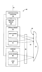
[0051] FIG. 4 shows a functional block diagram of a borehole instrument
90 according to another embodiment, in which two image sensors are used.
The instrument 90 is similar to the instrument 10 and for clarity, and
only differences will be described in detail. For other features and
aspects of the instrument 90, the description of the instrument 10 can be
referenced, with like reference numerals identifying like elements.
[0052] The borehole instrument 90 includes a borehole profiler 94
similar to the borehole profiler 54. The borehole profiler 94 includes an
image sensor 96 positioned to capture laser light emitted by the laser 76
and reflected from the inside wall 82 of the borehole 12. The image
sensor 96 thus measures the borehole profile, while the different image
sensor 74 of the optical imager 52 can be dedicated to capturing images
of the borehole wall 82.
[0053] The image sensor 96 may be a high-speed and high-resolution CCD
or CMOS image sensor, or similar. In this embodiment, the image sensor 96
is configured to capture light of the wavelength band of the laser 76.
[0054] The image sensors 74, 96 may be of the same or different types.
The image sensors 74 and 96 may have different sets of optics.
[0055] With reference to FIGs. 3 and 4, in other embodiments, the
borehole profiler 54 is an acoustic device that includes a rotating
transducer that transmits an acoustic pulse into the borehole 12 and
CA 02845910 2014-03-12
measures the returning amplitude and travel time of the pulse reflected
from the borehole wall 82. Profile data 34 is thus captured by the
rotating transducer. This embodiment is suitable for use in wet boreholes
and when moving parts can be tolerated.
[0056] In view of the above, it should be apparent that the present
invention allows data capture to be performed faster. For example, up
until now a 1000 meter borehole may have required as much as 800 minutes
of scanning time (i.e., 400 minutes each for a profile pass and a
separate imaging pass). With the present invention, a single pass of 400
minutes captures depth-aligned and mutually oriented profile data and
image data, resulting in substantial time saved. Moreover, increased data
capture speed allows for faster movement in the borehole, such that total
capture time may be reduced to less than 200 minutes.
[0057] Further, there can be a reduction in the amount of manual work
and potential for error in manually aligning profile data and image data.
This may also further save time.
[0058] In addition, image and profile data can be acquired with higher
resolution than currently available. For example, existing acoustic
profile technology is limited by a 2 mm acoustic beam diameter, which
means that the typical highest resolution possible is a 2mm x 2 mm pixel
size or a maximum annular resolution of 288 measurements per 360 degrees.
A 2 mm pixel size is usually not adequate to measure roughness in situ.
When using the laser as discussed herein, pixel size can be as small as
0.5 mm x 0.5 mm, which can result in an annular resolution of
approximately 1000 measurements per 360 degrees.
[0059] In addition, it is advantageous that use of the laser for
profile measurements allows such measurements to be taken in wet, dry,
and partially dry boreholes.
[0060] While the foregoing provides certain non-limiting example
embodiments, it should be understood that combinations, subsets, and
variations of the foregoing are contemplated. The monopoly sought is
defined by the claims.
11