Note: Descriptions are shown in the official language in which they were submitted.
PATHWAY PLANNING SYSTEM AND METHOD
BACKGROUND
1. Technical Field
[0001] The present disclosure relates to a system and method for planning a
pathway through an anatomical luminal network of a patient.
2. Discussion of Related Art
[0002] During a surgical procedure clinicians often use CT images for
determining
a plan or pathway for navigating through the luminal network of a patient. It
is often
difficult, however, for the clinician to effectively plan a pathway based on
CT images
alone, especially in the smaller branches of the bronchial tree where CT
images
typically do not provide sufficient resolution for accurate navigation.
[0003] To assist a clinician in planning a pathway through a luminal
network,
automated pathway planning systems and methods have been implemented that
automatically generate a pathway from a target designated on a CT image to the
an
entry point of a patient, e.g., a patient's mouth, nose, other natural entry
points or an
artificial entry point such, for example, as an incision. One example of an
automated
pathway planning system and method can be found in U.S. Patent No. 8,218,846.
[0004] When using a fully automated pathway planning system, however, the
medical device may reach the end of the pathway in an orientation where the
working
end of the medical device is not oriented toward the target. In this example,
a side of
the medical device may be oriented towards the target instead of the working
end and
it may be difficult or impossible for the clinician to gain access to the
target with
the working end. In particular, when navigating through the small airways of
the
bronchial tree it may be difficult or even impossible to flex or turn the
working end of
CA 2845918 2020-04-30
CA 02845918 2014-03-12
the medical device towards a target when the target is located perpendicular
to the
path of travel of the medical device through the small airways.
SUMMARY
[0005] Systems and methods for planning a pathway through an anatomical
lurninal network of a patient are provided.
[0006] In an aspect of the present disclosure, a system for planning a
pathway
through an anatomical luminal network of a patient is disclosed including a
computing
device including at least one processor; a display device in communication
with the
computing device; a user interface configured for display on the display
device and
configured to guide a user through a pathway planning procedure. The user
interface includes a patient selection window configured to receive a user
input to
select a patient having CT image data on which to perform pathway planning; a
target selection window configured to receive a user input to select at least
one target
from the CT image data; and an airway finder window configured to generate at
least
one pathway from the at least one target to an entry point of the anatomical
luminal
network in response to a user input.
[0007] In an aspect of the present disclosure, the patient selection window
is
configured to import patients and CT image data from at least one memory
device
associated with the computing device.
[0008] In an aspect of the present disclosure, the at least one processor
is
configured to generate a three-dimensional CT volume from the CT image data
selected by the user.
[0009] In an aspect of the present disclosure, the at least one processor
is
configured to generate a three-dimensional model of the patient's bronchial
tree from
the CT image data selected by the user for displaying on the display.
[00010] In an aspect of the present disclosure, the target selection window
includes:
a CT image window configured to display a slice of the CT image data; a
localizer
window configured to display an image of at least one lung, the localizer
window
including a localizer configured to identify a location of the displayed slice
relative to
2
CA 02845918 2014-03-12
the at least one lung; and a target selection element configured to select the
target
from a displayed slice of CT image data in response to a user input.
[00011] In an aspect of the present disclosure, the CT image window is
configured
to display at least one other slice of the CT image data in response to a user
input
and the localizer is configured to move relative to the image of the at least
one lung
to identify the location of the displayed at least one other slice relative to
the at least
one lung.
[00012] In an aspect of the present disclosure, the airway finder window is
configured to display a CT image including the selected at least one target,
the CT
image rotatable about a pre-defined axis to assist the user in identifying an
airway of
the anatomical luminal network.
[00013] In an aspect of the present disclosure, the pre-defined axis is an
axis
defined from the target to a known airway of the anatomical luminal network.
[00014] In an aspect of the present disclosure, the pre-defined axis is an
axis
defined from the target to a portion of a trachea in the anatomical lumina!
network.
[00015] In an aspect of the present disclosure, the pre-defined axis is an
axis
defined by a pathway from the target to a waypoint.
[00016] In an aspect of the present disclosure, the pre-defined axis is an
axis
defined by a pathway from a first waypoint to a second waypoint.
[00017] In an aspect of the present disclosure, the airway finder window
further
includes a rotation interface configured to identify an amount of rotation of
the CT
image about the pre-defined axis relative to an initial rotational orientation
of the CT
image.
[00018] In an aspect of the present disclosure, a method for planning a
pathway
through an anatomical luminal network of a patient is disclosed including the
steps of:
importing CT image data of a patient selected by a user input; generating a
three-
dimensional CT volume from the CT image data; displaying a slice of the three-
dimensional CT volume; receiving a user input identifying a target; defining
an axis of
3
CA 02845918 2014-03-12
rotation from the identified target to a known airway of the three-dimensional
CT
volume; rotating a slice of the three-dimensional CT volume about the axis of
rotation;
receiving an input from a user indicating a location for a new waypoint in an
airway of
the rotated slice; setting a first waypoint in the identified airway; and
generating a first
pathway from the target to the first waypoint.
[00019] In an aspect of the present disclosure, the method further includes
the
steps of: determining if the first waypoint is located in a known airway of
the three-
dimensional CT volume; and automatically completing a pathway from the first
waypoint to the entry point if the first waypoint is located in a known
airway.
[00020] In an aspect of the present disclosure, the method further includes
the
steps of: defining the axis of rotation along the first pathway; rotating a
slice of the
three-dimensional CT volume about the axis of rotation; receiving an input
from a
user indicating a location for a new waypoint in an airway of the rotated
slice; setting
a second waypoint in the identified airway; and generating a second pathway
from
the first waypoint to the second waypoint.
[00021] In an aspect of the present disclosure, the method further includes
the
steps of: determining if the second waypoint is located in a known airway of
the
three-dimensional CT volume; and automatically completing a pathway from the
second waypoint to the entry point if the second waypoint is located in a
known
airway.
[00022] In an aspect of the present disclosure, a non-transitory computer-
readable
storage medium encoded with a program is disclosed, that, when executed by a
processor causes a user interface to perform the steps of: importing CT image
data
of a patient selected by a user input; generating a three-dimensional CT
volume from
the CT image data; displaying a slice of the three-dimensional CT volume;
receiving
a user input identifying a target; defining an axis of rotation from the
identified target
to a known airway of the three-dimensional CT volume; rotating a slice of the
three-
dimensional CT volume about the axis of rotation; receiving an input from a
user
indicating a location for a new waypoint in an airway of the rotated slice;
setting a first
4
CA 02845918 2014-03-12
waypoint in the identified airway; and generating a first pathway from the
target to the
first waypoint.
[00023] In an aspect of the present disclosure, the program further causes the
user
interface to perform the steps of: determining if the first waypoint is
located in a
known airway of the three-dimensional CT volume; and automatically completing
a
pathway from the first waypoint to the entry point if the first waypoint is
located in a
known airway.
[00024] In an aspect of the present disclosure, the program further causes the
user
interface to perform the steps of: defining the axis of rotation along the
first pathway;
rotating a slice of the three-dimensional CT volume about the axis of
rotation;
receiving an input from a user indicating a location for a new waypoint in an
airway of
the rotated slice; setting a second waypoint in the identified airway; and
generating a
second pathway from the first waypoint to the second waypoint.
[00025] In an aspect of the present disclosure, the program further causes the
user
interface to perform the steps of: determining if the second waypoint is
located in a
known airway of the three-dimensional CT volume; and automatically completing
a
pathway from the second waypoint to the entry point if the second waypoint is
located
in a known airway.
[00026] Any of the above aspects and embodiments of the present disclosure may
be combined without departing from the scope of the present disclosure.
BRIEF DESCRIPTION OF THE DRAWINGS
[00027] Objects and features of the presently disclosed system and method will
become apparent to those of ordinary skill in the art when descriptions of
various
embodiments thereof are read with reference to the accompanying drawings, of
which:
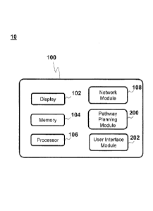
[0010] FIG. 1
is a schematic diagram of a computing device for pathway planning
in accordance with an embodiment of the present disclosure;
CA 02845918 2014-03-12
[0011] FIG. 2A is a view of a CT scan image of a patient's lungs taken from
the
Axial direction in accordance with an embodiment of the present disclosure;
[0012] FIG. 2B is perspective view a patient's body illustrating the Axial
direction
in accordance with an embodiment of the present disclosure;
[0013] FIG. 20 is a view of a CT scan image of a patient's lungs taken from
the
Coronal direction in accordance with an embodiment of the present disclosure;
[0014] FIG. 2D is perspective view of a patient's body illustrating the
Coronal
direction in accordance with an embodiment of the present disclosure;
[0015] FIG. 2E is a view of a CT scan image of a patient's lungs taken from
the
Sagittal direction in accordance with an embodiment of the present disclosure;
[0016] FIG. 2F is perspective view of a patient's body illustrating the
Sagittal
direction in accordance with an embodiment of the present disclosure;
[0017] FIG. 3 is a flow chart illustrating the four phases of pathway
planning in
accordance with an embodiment of the present disclosure;
[0018] FIG. 4 is an illustration of a user interface for the selection of
patient data in
accordance with an embodiment of the present disclosure;
[0019] FIG. 5 is a flow chart of a method of selecting patient data in
accordance
with an embodiment of the present disclosure;
[0020] FIG. 6 is an illustration of a user interface for adding a target to
a pathway
plan in accordance with an embodiment of the present disclosure;
[0021] FIG. 7 is a flow chart of a method of adding a target to a pathway
plan in
accordance with an embodiment of the present disclosure;
[0022] FIG. 8 is an illustration of a user interface for editing target
details of an
added target in accordance with an embodiment of the present disclosure;
[0023] FIG. 9 is an illustration of a user interface for reviewing a 3D map
in
accordance with an embodiment of the present disclosure;
6
CA 02845918 2014-03-12
[0024] FIG. 10 is a flow chart of a method of reviewing a 30 map in
accordance
with an embodiment of the present disclosure;
[0025] FIG. 11A is an illustration of a user interface for finding a
pathway from a
target to an entry point of a patient;
[0026] FIG. 11B is an illustration of the user interface of FIG. 11A after
a CT
image of the user interface has been rotated about an initial axis;
[0027] FIG. 11C is a perspective view of a 3D model of a patient's
bronchial tree,
illustrating an initial axis of rotation in accordance with an embodiment of
the present
disclosure;
= [0028] FIG. 11D is an illustration of the user interface of FIG.
11B after a waypoint
has been added and a pathway between the target and the waypoint has been
created with the CT image rotated about the axis of the pathway;
[0029] FIG. 11E is an illustration of the user interface of FIG. 11D after
a second
waypoint has been added and a second pathway between the waypoint and the
second waypoint has been created;
[0030] FIG. 11F is an illustration of the user interface of FIG. 11E after
the CT
image has been rotated about the axis of the second pathway to display a known
airway;
[0031] FIG. 11G is an illustration of the user interface of FIG. 11F after
a third
waypoint has been added within the known airway and the pathway has been
automatically completed;
[0032] FIG. 12 is a flow chart of a method of finding a known airway and
creating
a pathway in accordance with an embodiment of the present disclosure;
[0033] FIG. 13 is an illustration of a user interface for the reviewing a
pathway
accordance with an embodiment of the present disclosure;
[0034] FIG. 14 is a flow chart of a method of reviewing a pathway in
accordance
with an embodiment of the present disclosure;
7
CA 02845918 2014-03-12
[0035] FIG. 15 is an illustration of a user interface for the reviewing a
target and
pathway and for creating additional targets and pathways in accordance with an
embodiment of the present disclosure;
[0036] FIG. 16 is an illustration of a user interface for the reviewing and
exporting
a pathway plan in accordance with an embodiment of the present disclosure; and
[0037] FIG. 17 is a flow chart of a method of reviewing and exporting
targets,
pathways, and pathway plans in accordance with an embodiment of the present
disclosure.
DETAILED DESCRIPTION
[0038] Although the present disclosure will be described in terms of a
specific
embodiment, it will be readily apparent to those skilled in this art that
various
modifications, rearrangements and substitutions may be made without departing
from
the spirit of the present disclosure. The scope of the present disclosure is
defined by
the claims appended hereto.
[0039] Referring now to FIG. 1, the present disclosure is generally
directed to a
pathway planning system 10 and method for planning a pathway through an
anatomical luminal network of a patient for use during an operation. The
pathway
planning system 10 may include a computing device 100 such as, for example, a
laptop, desktop, tablet, or other similar device, having a display 102, memory
104,
one or more processors 106 and/or other components of the type typically found
in a
computing device. Display 102 may be touch sensitive and/or voice activated,
enabling display 102 to serve as both an input and output device.
Alternatively, a
keyboard (not shown), mouse (not shown), or other data input devices may be
employed.
[0040] Memory 104 includes any non-transitory, computer-readable storage
media for storing data and/or software that is executable by processor 106 and
which
controls the operation of the computing device 100. In an embodiment, the
memory
104 may include one or more solid-state storage devices such as flash memory
chips. In an alternative embodiment, the memory 104 may be mass storage
8
CA 02845918 2014-03-12
connected to the processor 106 through a mass storage controller (not shown)
and a
communications bus (not shown). Although the description of computer-readable
media contained herein refers to a solid-state storage, it should be
appreciated by
those skilled in the art that computer-readable storage media can be any
available
media that can be accessed by the processor 106. That is, computer readable
storage media includes non-transitory, volatile and non-volatile, removable
and non-
removable media implemented in any method or technology for storage of
information such as computer-readable instructions, data structures, program
modules or other data. For example, computer-readable storage media includes
RAM, ROM, EPROM, EEPROM, flash memory or other solid state memory
technology, CD-ROM, DVD, or other optical storage, magnetic cassettes,
magnetic
tape, magnetic disk storage or other magnetic storage devices, or any other
medium
which can be used to store the desired information and which can be accessed
by
the computing device 100.
[0041] Computing device 100 may also include a network module 108 connected
to a distributed network or the internet via a wired or wireless connection
for the
transmission and reception of data to and from other sources. For example,
computing device 100 may receive computed tomographic (CT) images of a patient
from a server, for example, a hospital server, internet server, or other
similar servers,
for use during pathway planning. Patient CT images may also be provided to
computing device 100 via a removable memory 104.
[0042] A pathway planning module 200 includes a software program stored in
memory 104 and executed by processor 106 of the computing device 100. As will
be
described in more detail below, pathway planning module 200 guides a clinician
through a series of steps to develop a pathway plan for later use during a
medical
procedure. Pathway planning module 200 communicates with a user interface
module 202 for displaying visual interactive features to a clinician on the
display 102
and for receiving clinician input.
[0043] As used herein, the term "clinician" refers to any medical
professional (i.e.,
doctor, surgeon, nurse, or the like) or other user of the pathway planning
system 10
9
CA 02845918 2014-03-12
involved in planning, performing, monitoring and/or supervising a medical
procedure
involving the use of the embodiments described herein.
[0044] Referring temporarily to FIGS. 2A-2F, as a practical matter the most
effective method of identifying targets involves the use of a computed
tomographic
(CT) image. By way of introduction, the use of CT images as a diagnostic tool
has
become routine and CT results are frequently the primary source of information
available to a clinician regarding the size and location of a lesion, tumor or
other
similar target of interest. This information is used by the clinician for
planning an
operative procedure such as a biopsy, but is only available as "offline"
information
which must typically be memorized to the best of the practitioner's ability
prior to
beginning a procedure. CT images are typically obtained by digitally imaging a
patient in slices in each of the Axial, Corona! and Sagittal directions. For
example,
FIG. 2A illustrates a slice of a CT image taken from the Axial direction,
i.e., as though
looking parallel to the spine of the patient as illustrated in FIG. 2B. FIG.
2C illustrates
a slice of a CT image taken from the Coronal direction, i.e., from a birds eye
view of
the patient as illustrated in FIG. 2D. FIG. 2E illustrates a slice of a CT
image taken
from the Sagittal direction, i.e., from a side of the patient as illustrated
in FIG. 2F. A
clinician may review the CT image data slice by slice from each direction when
attempting to identify or locate a target.
[0045] Referring now to FIG. 3, in an embodiment, pathway planning using
the
pathway planning module 200 may be performed in four separate phases. In a
first
phase Si, a clinician selects a patient for pathway planning. In a second
phase S2,
the clinician adds a target. In a third phase S3, the clinician creates the
pathway to
the target. Finally, in the fourth phase S4, the clinician reviews and accepts
the plan
and may export the plan for use in a medical procedure. The clinician may
repeat
either or both of the second and third phases S2 and S3 as needed to select
additional targets and/or create additional pathways for a particular patient.
For
example, the clinician may select additional targets and may create a pathway
to
each target. The clinician may also or alternatively create multiple pathways
the
CA 02845918 2014-03-12
same target. With reference to FIGS. 4-16, each of stages S1-S4 will now be
described in more detail below.
[0046] As used herein, the term "window" refers to any screen, image,
overlay,
user interface or combination thereof, projected or provided on the display
102 by
user interface 202.
[0047] Referring now to FIGS. 4 and 5, in phase Si, user interface 202
presents a
clinician with a window 210 for selecting patient data 212 on which to perform
pathway planning. FIG. 4 illustrates user interface 202 including window 210
while
FIG. 5 illustrates a method of selecting patient data according to an
embodiment of
the present disclosure. User interface 202 initially starts the method of
selecting
patient data at step S500 by opening window 210 for the clinician's review.
Window
210 includes a selectable source location menu 214 that provides the clinician
with
the ability to select a source from which patient data 212 is received for use
in
pathway planning. In step S510 the clinician selects from a number of storage
or
memory devices including, for example, cd, dvd, blue-ray, other insertable
optical
media, universal serial bus (USB) memory devices, external or internal hard
drives,
solid state storage devices, or any other type of memory or storage 104
connected to
or in data communication with computing device 100, as described above. The
window 210 may also provide access to patient data 212 stored in a remote
location
such as, for example, a server on a network or the internet. Source location
menu
214 may allow the clinician to select a single source of patient data or may
allow the
clinician to select multiple sources of patient data at the same time. Source
location
menu 214 may also include an option to list patients from all sources. In step
S504,
the clinician may search through the list of patients or may input a search
term in a
search box 216 to narrow down the list of patients to those meeting a selected
criteria
such as, for example, a patient's first or last name, ID number, date of birth
or other
similar criteria. Once the clinician has selected the desired patient, the
clinician
proceeds to step S506.
[0048] In step 506, once a patient is selected by the clinician, a drop
down menu
218 is displayed for the patient including a list of the patient's available
CT images
11
220 and any pathway plans 222 for the selected patient that have been
previously
created for each CT image 220. The clinician may choose to create a new plan
based
on the CT image 220 by selecting the create new plan option 224 and proceeding
to
step S510 or may open a previously created plan by selecting an open plan
option 226
and proceeding to step S514, if a previously created plan is present for the
selected
CT image 220. When the create new plan option 224 is selected, the CT images
220
are imported, preferably in a DICOM format, into the pathway planning module
200.
The computing device 100 processes the CT images 220 and assembles them into a
three-dimensional CT volume by arranging the CT images 220 in the order they
were
taken and spacing them apart according a distance between slices set on the CT
scanning device when they were taken. Pathway planning module 200 may perform
a data fill function to create a seamless three-dimensional (3D) model or CT
volume of
the patient's bronchial tree. The
pathway planning module 200 uses the
newly-constructed CT volume to generate a three-dimensional map of the airways
in
the bronchial tree. The three dimensional map can either be skeletonized, such
that
each airway is represented as a line, or it may include airways having
dimensions
representative of their respective diameters. Preferably, when the three
dimensional
map is being generated, the airways are marked with an airflow direction
(inhalation,
exhalation, or separate arrows for each) for later use. Technologies for
generating
three-dimensional CT volumes and models are described in commonly assigned
U.S.
Pat. Nos. 6,246,784 and 6,345,112 both to Summers et al., as well as the
references
cited therein.
[0049]
Window 210 also includes a capture screen option 228 that allows the
clinician to capture an image of the current screen shown on the display 102,
for
example, window 210, and save the captured image to memory. The capture screen
option 228 may also be configured to remove patient specific data from the
captured
image to protect patient privacy. The removal of patient specific data may be
an option
selectable by the clinician and may be set to "on" by default.
12
CA 2845918 2020-04-30
CA 02845918 2014-03-12
[0050]
Referring now to FIGS. 6-8, if the clinician has selected the create new
plan option 224 from window 210, the method proceeds to step S512 and phase
S2,
adding a target. FIGS. 6 and 8 illustrate user interface 202 including windows
230
and 244 while FIG. 7 illustrates a method of adding a target according to an
embodiment of the present disclosure. When phase S2 is initiated the method
proceeds to step S700 and user interface 202 opens a window 230 for
identification
and selection of a target 232 on which to perform pathway planning. In window
230,
the clinician is provided with a slice 234 of the CT image data in a main
window 236.
The slice 234 may be taken from the CT image data in any one of the Axial,
Coronal
and Sagittal directions. The clinician may freely switch the slice 234 shown
in the
main window 236 between slices 234 from the Axial, Corona! and Sagittal
directions
at any time. In the illustrated example, a slice 234 from the Axial CT image
data is
provided. It is important to note that by only showing a single slice and
direction at a
time, for example, only a slice 234 from the Axial CT image data, the
clinician is
provided with a simple and clean interface from which to select a target.
The
clinician may manipulate and relocate the image of the selected slice 234 in
the main
window 236 and may zoom in or out on the selected slice 234 to obtain an
enlarged
or reduced view of a particular portion of the selected slice 234.
[0051] Window
230 also includes a localizer 238 which provides a general
overview of the patient's CT image data for use by the clinician. In the
illustrated
example, localizer 238 provides a localizer window 240 including generic view
of a
patient's lungs from the Corona! direction. The localizer window 240 may, for
example, display a CT image from the Coronal direction, a fluoroscopy-like
image, or
other similar images that provide a clinician with a view of the patient's
lungs.
Localizer 238 includes a location element 242, for example, a line or bar,
extending
across localizer window 240 which provides a clinician with a location of the
selected
slice 234 displayed in main window 236 relative to the patient's lungs as
displayed by
the localizer 238. Location element 242 is selectable by the clinician and
moveable
or slidable relative to the localizer window 240 to allow the clinician to
scroll through
the CT image slices of the patient's lungs displayed on the main window 236.
For
13
CA 02845918 2014-03-12
example, the CT image slices may be scrolled through or displayed in a
sequential
order defined by the CT image data. The clinician may also or alternatively
click on
or select a portion of the localizer window 240 to move localizer 238 to the
selected
location in the patient's lungs. The clinician may also or alternatively
scroll through
the CT image slices of the patient's lungs displayed in the main window 236
via an
input device such as, for example, a mouse wheel or other device without
interacting
directly with user interface 202. When another direction is selected for
display on
main window 236, for example, the Coronal direction, localizer 238 may display
a
generic view of one of the other directions, for example, the Axial or
Sagittal direction.
Localizer 238 provides the clinician with a general reference for where a
particular
lesion or other target 232 is located in the patient's lungs. Localizer 238
may also
display one or more previously selected targets for the clinician's reference.
[0052] In step S702, the clinician scrolls through the CT image slices 234
to
identify a target 232 on the CT image. In step S704, once a target 232 has
been
identified in the current CT slice 234, the clinician may click on or
otherwise select the
target 232 from the main window 236 using a target selection element 243, for
example, a crosshair, mouse pointer, hand, or other similar selection element.
The
clinician may, for example, drag the CT image displayed on the main window 236
so
that the target selection element 243 is positioned over the target 232, or
alternatively,
may directly select target 232 by clicking on the target 232 using a mouse
(not
shown) or other input device. If display 102 is touch-sensitive, the clinician
may
touch the target 232 on display 102 to select the target 232. The target 232
may
then be added to the plan in step S706 by selecting the add a target option
245.
[0053] Referring now to FIG. 8, once a target 232 has been added, a target
details
window 244 is displayed by user interface 202. Target details window 244 may
overlay window 230 or may replace window 230. Target details window 244
provides
the clinician with the selected target 232 as shown in enlarged or zoomed
versions of
the Axial view 246, Coronal view 248 and Sagittal view 250. In step S708, the
clinician may input width, height, and depth dimensions for the target 232,
name the
target 232, and add additional comments relating to the target 232. In
addition, a
14
CA 02845918 2014-03-12
target sizing element 252, e.g., a crosshair or other similar element, is
positioned
over the target 232 in each of views 246, 248, 250 and is manipulatable or
movable
by the clinician to center the target 232 in the target sizing element 252 in
each view
246, 248, 250. Target sizing element 252 also includes an adjustable boundary
ring
254 that is manipulatable by the clinician to resize the dimensions of the
target 232.
For example, the clinician may resize the boundary ring 254 on each of the
Axial view
246, Coronal view 248 and Sagittal view 250 to accurately define the
dimensions of
the target 232. Boundary ring 254 may be circular, oval or other similar
geometric
shapes and the shape of the boundary ring 254 may be adjusted to substantially
match the general dimensions of the target 232. In an embodiment, boundary
ring
254 may be adjusted in a non-geometric manner by the clinician, for example, a
free-
form manipulation of boundary ring 254, to conform to non-geometric dimensions
of
the target 232. It is important to note that because the target 232 is a three
dimensional object such as, for example, a lesion, tumor, or the like, and
each view
246, 248, 250 is taken from a different direction, manipulation and adjustment
of the
boundary ring 254 on one of the views 246, 248, 250 by the clinician may
result in a
change or adjustment of the boundary ring 254 in one or both of the remaining
views
246, 248, 250. In this manner the clinician may accurately select the target
'dimensions and the location of the target 232 in all three views, effectively
mapping
the target to specific coordinates and dimensions in a 3-D coordinate space.
In step
S710, once the dimensions and location of target 232 have been selected by the
clinician the clinician selects the save target option 256 and proceeds to a
review of
the generated three dimensional map of the patient's bronchial tree in step
S712.
[0054]
Referring now to FIGS. 9 and 10, after the clinician has selected the save
target option 256 of window 230, the method proceeds to step S1000, reviewing
the
3D map of the bronchial tree. In step S1000, user interface 202 opens a window
260
for review of the three dimensional map generated by the pathway planning
module
200. Window 260 includes a three dimensional map window 262 displaying a three
dimensional model 264 of the patient's bronchial tree and a scan window 266
displaying a CT image from one of the Axial, Coronal and Sagittal directions
for the
CA 02845918 2014-03-12
clinician's reference. In the illustrated embodiment, the CT image from the
Coronal
direction is displayed. The CT image from the Coronal direction is displayed
because
the Coronal direction provides images of the patient's bronchial tree from the
bird's
eye or frontal view and is more likely to display to the clinician major
recognizable
features of the bronchial tree, for example, trunks and branches of the major
airways.
By comparing the CT image to the three dimensional model 264, the clinician is
able
to determine or verify that the three dimensional model 264 includes the major
recognizable features of the patient's bronchial tree and also that there are
no gross
abnormalities in the three dimensional model 264 when compared to the CT
image.
In step S1002, the clinician rotates the three dimensional model as needed by
manipulating a rotation slider 268 of three dimensional map window 262 to
determine
if the 3D map is acceptable. In step S1004, if the clinician is satisfied that
the three
dimensional model 264 is substantially accurate, for example, the major or
central
airways are sufficiently illustrated, the clinician selects the approve map
option 270
and proceeds to the phase S3 and the airway finder. If the 3D map is not
acceptable,
the clinician proceeds to step S1006 and returns to step S500 to select new
patient
data, for example, a new patient or a new CT scan for the same patient.
[0055]
Referring now to FIGS. 11A-11G and 12, after the clinician has selected
the approve map option 270 of window 260, the method proceeds to phase S3 and
step S1200 to start the airway finder. FIGS. 11A-11B and 11D-11G illustrate
user
interface 202 including window 272, FIG. 11C illustrates an initial axis "A"
for use by
the airway finder, and FIG. 12 illustrates a method of finding an airway and
completing a pathway according to an embodiment of the present disclosure. In
step
S1200, referring initially to FIGS. 11A-11C, user interface 202 opens a window
272
for creating a pathway from the target 232 to the an entry point of the
patient, for
example, a natural orifice such as the mouth or nose, or an artificial entry
point such
as an incision. Window 272 includes an airway finder 274 displaying a CT image
276
including the target 232 and a rotation interface 278 describing the rotation
of the CT
image 276 about a specified axis. In an embodiment, upon initial opening of
window
272, only the target 232 is shown on the CT image 276 of the airway finder
window
16
CA 02845918 2014-03-12
274 and rotation indicators 280, e.g., arrows 280a and rotation bar 280b, on a
rotation interface 278 are aligned.
Rotation interface 278 provides rotational
information regarding a relative rotation of CT image 276 about the specified
axis.
Referring now to FIG. 11B, a target marker 232A is displayed on the CT image
276
and is positioned over the target 232 to illustrate the location of target 232
to the
clinician. A lead line 232B extends from a center of target marker 232A and is
moveable by the clinician through movement of a pointer, mouse or other input
devices. For example, the movement of an input device by the clinician moves
an
end 232C of lead line 232B that extends away from the target 232. The
clinician
uses lead line 232B to select an appropriate airway as will be described in
more
detail below with respect to step S1208.
[0056] In an
embodiment, referring briefly to FIG. 11C, an initial axis "A" is set in
step S1202 upon the initial opening of window 272 and is defined along an axis
taken
from the target 232 to a central portion of the tracheal lumen of the patient.
By
defining the initial axis "A" along axis from the target 232 to the trachea,
the likelihood
that a clinician can find an airway near the target 232 that will connect the
target 232
to the entry point is increased. This is due to the tree like or branching
nature of the
bronchial tree. In other embodiments, the initial axis "A" may be defined
along an
axis taken from the target 232 to any other portion of the patient's bronchial
tree, for
example, to a central portion of the closest main branch of bronchial tree or
to the
closest known airway of the 3D map of the patient's bronchial tree.
[0057] In
step S1204, the clinician rotates the CT image 276 about the initial axis
by, for example, rolling a mouse wheel, manipulating another input device,
and/or by
manipulating a portion of user interface 202, for example, rotation interface
278. As
the clinician rotates the CT image 276 about the initial axis, indicators 280
on the
rotation interface 278 move relative to one another, for example, the rotation
bar
280b moves relative to the arrows 280a, in a corresponding direction along
rotation
interface 278 to indicate the amount of rotation relative to the initial view.
When the
rotation bar 280b reaches the end of rotation interface 278 after continued
rotation in
the same direction by the clinician, rotation bar 280b will disappear from the
end of
17
CA 02845918 2014-03-12
the rotation interface 278, reappear on an opposite end of rotation interface
278, and
continue to slide along rotation interface 278 in the same direction. When the
clinician has rotated the CT image 276 a full rotation about the initial axis,
indicators
280, e.g., arrows 280a and rotation bar 280b, will once again be aligned at
the center
of rotation interface 278.
[0058] Referring now to FIGS. 11B and 11D, when rotating the CT image 276
about the initial axis, the clinician assesses the CT image 276 in step S1206
to
determine whether an airway 282 near the target 232 is present. For example,
an
area of darkness in the CT image 276 that extends away from the target 232 or
extends near the target 232 may be an indication that an airway 282 is
present. If
the clinician determines that an airway 282 is present, the method proceeds to
step
S1208 and the clinician positions end 232C of lead line 232B at the determined
location within the airway 282 on the CT image 276 to create a pathway
waypoint
282a on the CT image 276. The pathway planning module 200 draws a pathway line
284 between the target 232 and the pathway waypoint 282a on the CT image 276
and proceeds to step S1210. In this way, the clinician defines the portion of
the
airway 282 closest to the target 232. If no airway 282 is present, the
clinician returns
to step S1204 and continues to rotate the CT image about the specified axis.
If the
pathway waypoint 282a is not positioned correctly or the clinician desires to
look for
another airway, the clinician may remove the pathway waypoint 282a and return
to
either of steps S1204 or S1208.
[0059] In step S1210, pathway planning module 200 determines whether the
pathway waypoint 282a selected by the clinician is located within a known
airway of
the three dimensional map generated by the pathway planning module 200. If the
pathway waypoint 282a is located within a known airway of the three
dimensional
map, the method proceeds to step S1214 and the pathway is automatically
completed by the pathway planning module 200 from the pathway waypoint 282a
through the known airways of the three dimensional map to the trachea and the
entry
point of the patient, as further illustrated below for waypoint 282a in FIG.
11G.
18
CA 02845918 2014-03-12
[0060] If the
pathway waypoint 282 is not located within a known airway of the
three dimensional map, the method proceeds to step S1212. Referring now to
FIGS.
11D and 11E, airway finder 274 displays a CT image 286 including the target
232,
target marker 232a, pathway waypoint 282a, pathway line 284, and rotation
interface
278, as described above. As illustrated in FIG. 11D, a lead line 282b having
an end
282c now extends from pathway waypoint 282a.
[0061] In
step S1212, the specified axis is set to an axis defined by pathway line
284. CT image 286 is rotatable about pathway line 284 instead of the initial
axis "A"
and rotation interface 278 displays the relative rotation of the CT image 286
about
the axis defined by pathway line 284. By defining the axis of rotation about
pathway
line 284, the likelihood of the clinician finding airways on CT image 286 that
connect
to the airway 282 including the pathway waypoint 282a is increased. After the
specified axis has been set to the axis of pathway line 284, the method
returns to
step S1204. When rotating the CT image 286 about the axis defined by pathway
line
284, the clinician assesses the CT image 286 to determine whether an airway
288
connected to the pathway including pathway waypoint 282a is present as
described
above. If the clinician determines that an airway 288 is present in step
S1206, the
method proceeds to step S1208 and the clinician positions end 282C of lead
line
282B at the determined location within the airway 288 on the CT image 286 to
create
a pathway waypoint 288a on the CT image 286. The pathway planning module 200
draws a pathway line 290 from pathway waypoint 282a to pathway waypoint 288a
on
the CT image 286, as illustrated in FIG. 11E. If the pathway waypoint 288a is
not
positioned correctly or the clinician desires to look for another airway, the
clinician
may remove the pathway waypoint 288a and return to either of steps S1204 or
S1208.
[0062] In
step S1210, referring now to FIGS. 11F, the pathway planning module
200 determines whether the pathway waypoint 288a selected by the clinician is
located within a known airway, e.g., airway 291, of the three dimensional map
generated by the pathway planning module 200. If the pathway waypoint 288a is
not
located within a known airway of the three dimensional map, the method
proceeds to
19
CA 02845918 2014-03-12
step S1212 and the clinician continues to set additional pathway waypoints as
described above until a pathway waypoint is located within a known airway of
the
three dimensional map.
[0063]
Referring now to FIG. 11G, a pathway waypoint 291a has been added in
the manner described above in airway 291. In this illustration, airway 291 is
a known
airway of the three dimensional map. The method proceeds to step S1214 and the
pathway 291b is automatically completed by the pathway planning module 200
from
the pathway waypoint 291a through the airway 291 and the known branches of the
three dimensional map of the bronchial tree to the entry point of the patient.
Once a
pathway is automatically completed, the method proceeds to step S1216 and a
pathway completed window 292 is displayed by the user interface 202 providing
the
clinician with a proceed to pathway review option 293a and an undo automatic
completion option 293a. The clinician may select the proceed to pathway review
option 293a to proceed to step S1218 and start review of the pathway.
Alternatively,
if the clinician would like to continue mapping waypoints using airway finder
274, the
clinician may select the undo automatic completion option 293b and return to
step
S1212 for the creation of further pathway waypoints as described above.
[0064] In
this manner a pathway plan is created for later use by a clinician during
a procedure or operation. Because the clinician can manually select and create
the
pathway and pathway waypoints that are closest to the target 232 prior to
automatic
completion, the clinician is able create a pathway plan that directly controls
the final
orientation of a medical device at the end of the pathway plan relative to the
target
232. This allows the clinician to create a pathway plan for the medical device
that will
allow the medical device to travel along the small airways of the patient in a
direction
that will allow the working end of the medical device to be oriented generally
toward
the target 232, where generally toward the target 232 includes any orientation
from
which the clinician may effectively gain access to the target 232 within the
limits of
the medical device used.
[0065]
Referring now to FIGS. 13 and 14, after the clinician has completed a
pathway, the method proceeds step S1400 and user interface 202 opens a window
294 for reviewing the pathway from the target 232 to the entry point of the
patient. FIG.
13 illustrates user interface 202 including window 294 while FIG. 14
illustrates a
method of reviewing a pathway according to an embodiment of the present
disclosure.
Window 294 includes a virtual window 295 and a three dimensional map window
296.
Three dimensional map window 296 displays a three dimensional model 298 of the
patient's bronchial tree similar to three dimensional map window 262. Virtual
window
295 displays a CT-based "virtual bronchoscopy" which depicts simulated views
similar
to those of actual bronchoscope views and includes a view selection tab 295a
for
selecting between a virtual bronchoscopy view, a local view, and radial view.
During
the virtual bronchoscopy, the clinician may switch between the virtual, local
and radial
views as needed to review the pathway. The virtual bronchoscopy view displays
a
virtual visualization of the airways, derived from the CT data, that is an
approximation
of the video image from a bronchoscope, the local view displays an elevated
perspective view of a cross-section of the CT volume through the current
navigation
location, and the radial view displays a cross-section of the CT volume that
is
perpendicular to the navigation location and local pathway segment. The
technology
of virtual bronchoscopy is described in commonly assigned U.S. Pat. Nos.
6,246,784
and 6,345,112 both to Summers et al., as well as the references cited therein.
[0066] In
step S1402, once the pathway has been created by the clinician, the user
reviews the plan, targets and pathways by following a fly-through virtual
bronchoscopy on virtual window 295. The user interface 202 generates a line
300 in
virtual window 295 which represents the created pathway. The clinician follows
the
line 300 from the entry point through the trachea and through the airways of
the
patient's bronchial tree until the line 300 reaches the target 232. As can be
appreciated, as the clinician follows the line 300 through the increasingly
smaller
airways of the patient's bronchial tree, the ability of the pathway planning
module 200
to resolve the smaller airways is increasingly difficult due to a lack of
resolution in the
imported CT images. Because of this lack of resolution, the simulated views of
the
virtual bronchoscopy displayed in virtual window 295 may eventually fail to
depict a
21
CA 2845918 2020-04-30
CA 02845918 2014-03-12
clear airway lumen. Regardless, the target 232 and line 300 will be displayed
in the
virtual window 295 to allow the clinician to utilize the system for pathway
planning
purposes.
,
[0067] As the clinician follows the line 300 through the patient's
bronchial tree to
the target 232, a corresponding marker 298a travels along the three
dimensional
model 298 to the target 232 indicating a location of the simulated view of the
virtual
window 295 relative to the three dimensional model 298. In step S1404, after
reviewing the virtual bronchoscopy the clinician determines whether the
pathway is
acceptable. If the pathway is acceptable the clinician may select the approve
option
299a and the method proceeds to steps S1408. If the pathway is not acceptable,
the
method proceeds to steps S1406 and the clinician may select the discard
pathway
and start over option 299b to return to the airway finder window 272 to edit
the
pathway or create a new pathway.
[0068] Referring now to FIGS. 15-17, once the clinician has reviewed and
accepted the pathway, the method proceeds to phase S4 and step S1700. FIGS. 15
and 16 illustrate user interface 202 including windows 302 and 316,
respectively,
while FIG. 17 illustrates a method of reviewing a plan according to an
embodiment of
the present disclosure. In step S1700, user interface 202 opens a window 302
including a three dimensional map window 304 and views of each of the Axial
306,
Coronal 308 and Sagittal 310 directions displaying the selected pathway.
Window
302 includes target tabs 312 and a pathway list 314. Target tabs 312 allow the
clinician to add additional targets and select already identified targets for
further
review. Pathway list 312 allows the clinician to review the pathways
associated with
a selected target tab 312 and to add a pathway for the selected target tab
312. In
step S1704, the clinician determines if the targets are acceptable. If the
targets are
not acceptable, the method proceeds to step S1706 and the pathway planning
module 200 returns the clinician to the add a target window 230 to add a new
target,
as described above. If the targets are acceptable, the method proceeds to step
S1708 and the clinician determines if the pathways are acceptable. If the
pathways
are not acceptable the method proceeds to step S1710 and the pathway planning
22
CA 02845918 2014-03-12
module 200 returns the clinician to the airway finder window 272 for creation
of
additional pathways, as described above. If both the targets and the pathways
are
acceptable, the clinician selects the finish and export option 315 and
proceeds to
plan review in step S1716.
[0069] Referring now to FIG. 16, in step S1716 user interface 202 opens a
window 316 including a three dimensional map window 318 and a list of the
targets
320 identified for the selected plan. Each target 320 is selectable by the
clinician to
display the associated pathways 322 and each pathway 322 is reviewable by the
clinician through the selection of a review option 324. Window 316 also
provides an
indication of whether the three dimensional map has been reviewed and approved
and whether the current plan has been exported. In step S1712, if the 3D map
has
not been approved, the clinician may re-review the three dimensional map by
selecting the review 3D map option 326. If the review 3D map option 326 has
been
selected, the method proceeds to step S1714 and the pathway planning module
200
returns the clinician to the review 3D map window 260 described above. If the
3D
map has been approved, the method proceeds to step S1716 and the clinician
determines whether the overall plan is acceptable. If the plan is not
acceptable, the
method proceeds to step S1718 and the pathway planning module 200 returns the
clinician to the patient selection window 210 described above. If the
clinician is
satisfied with the plan, the method proceeds to step S1720 and the clinician
may
export the plan for use during a surgical procedure by selecting the export
option 328.
The plan may be exported to any form of non-transitory computer readable
medium,
memory or storage device as described above for memory 104 including, for
example,
a memory or storage on the device 100, a removable storage device, exported by
transmission across a wired or wireless connection to a remote or server
memory,
etc.
[0070] With reference to FIGS. 4, 6, 15 and 16 the user interface 202 may
include
one or more navigation bars that are manipulatable by the clinician to return
to or
repeat any of the above phases and/or steps. For example, as illustrated in
FIG. 4,
the clinician may manipulate a navigation bar 330 to switch between the
phases.
23
The clinician may also be provided with the option to return to a previous
step or
window in any of the user interface 202 windows.
[0071] As
noted above, the present disclosure employs CT images for the pathway
planning. CT images are also typically used by the clinician during a medical
procedure for the navigational purposes. The CT images are preferable to other
imaging modalities because they have their own system of coordinates. Matching
two
systems of coordinates, e.g., that of the CT images and that of the patient,
is commonly
known as registration. Registration is generally performed by identifying
locations in
= both the CT images and on or inside the body, and measuring their
coordinates in both
systems.
[0072]
Methods of manual and semi-automated registration of CT data and patient
data are described in detail in for example U.S. Patent No. 7,233,820 assigned
to
Covidien LP. Because manual registration is somewhat time consuming and
requires
multiple steps, many practitioners rely on the automatic registration
techniques
= described below. However, in some instances, particularly if the CT image
data is not
of sufficient quality it may still be necessary or desirable to conduct manual
registration.
[0073]
Automatic registration has become the norm for most procedures because
while the manual fiducial point designation of the above referenced
registration
techniques is highly effective, the choice of number of points sampled
necessarily
represents a tradeoff between accuracy and efficiency. Similarly, while the
semi-
automated technique is a viable option it requires an image sensor at the
distal end of
the catheter assembly which adds increased complexity to the system.
[0074]
Automatic registration techniques are described in detail in commonly
assigned U.S. Patent Application Publication No. 2011/0085720.
Automatic
registration between a digital image of a branched structure and a real-time
indicator
representing a location of a sensor inside the branched structure is achieved
by using
a sensor to "paint" a digital picture of the inside of the structure. Once
enough location
data has been collected, registration is achieved. The registration is
"automatic" in the
24
CA 2845918 2020-04-30
sense that navigation through the branched structure necessarily results in
the
collection of additional location data and, as a result, registration is
continually refined.
[0075]
Although embodiments have been described in detail with reference to the
accompanying drawings for the purpose of illustration and description, it is
to be
understood that the inventive processes and apparatus are not to be construed
as
limited thereby. It will be apparent to those of ordinary skill in the art
that various
modifications to the foregoing embodiments may be made without departing from
the
scope of the disclosure.
CA 2845918 2020-04-30