Note: Descriptions are shown in the official language in which they were submitted.
CA 02845954 2014-03-14
Blakes Ref: 11053/00002
1 REMOTE START CONTROL SYSTEM FOR A VEHICLE WITH A BUS
2 CONTROLLABLE TRANSMISSION AND ASSOCIATED METHODS
3
4 Field of the Invention
[0001] The present invention relates to the field of remote vehicle starting,
and, more
6 particularly, to remote vehicle starting devices and related methods.
7
8 Background of the Invention
9 [0002] Remote vehicle starting systems are widely used to allow a user to
start a vehicle before
entering the vehicle, so as to allow the engine of the vehicle to warm up to
operating
11 temperatures, for example. A typical remote starting system, for
example, includes a central
12 processor or controller connected to a starter circuit for the vehicle
engine to cause the starter
13 circuit to start the vehicle engine. A typical remote starting system
also includes a receiver
14 associated with the controller that cooperates with one or more remote
transmitters typically
carried by the user as disclosed, for example, in U.S. Pat. No. 4,383,242 to
Sassover et al. and
16 U.S. Pat. No. 5,146,215 to Drori. The remote transmitter may be used to
operate the remote
17 start system. Also related to remote control of a vehicle function U.S.
Pat. No. 5,252,966 to
18 Lambropoulous et al. discloses a remote keyless entry system for a
vehicle. The keyless entry
19 system permits the user to remotely open the vehicle doors or open the
vehicle trunk using a
small handheld transmitter.
21 [0003] Some remote start systems are connected to other vehicle devices
to provide
22 functionality in addition to remote starting. Unfortunately, many prior
remote start systems
23 needed to be directly connected by wires to individual vehicle devices.
In other words, such a
24 remote start system was hardwired to various vehicle components,
typically by splicing into
vehicle wiring harnesses or via interposing T-harnesses and connectors. The
number of
26 electrical devices in a vehicle has increased so that the size and
complexity of wiring harnesses
27 also increased. For example, the steering wheel may include horn
switches, an airbag, turn-
28 signal and headlight switches, wiper controls, cruise control switches,
ignition wiring, an
29 emergency flasher switch, and/or radio controls. Likewise, a door of a
vehicle, for example, may
include window controls, locks, outside mirror switches, and/or door-panel
light switches.
31 [0004] In response to the increased wiring complexity and costs, vehicle
manufacturers have
32 reduced the amount of wiring within vehicles to reduce weight, reduce
wire routing problems,
33 decrease costs, and reduce complications which may arise when
troubleshooting the electrical
34 system. For example, some manufacturers have adopted multiplexing
schemes to reduce
cables to three or four wires and to simplify the exchange of data among the
various onboard
1
22522517.1
CA 02845954 2014-03-14
Blakes Ref: 11053/00002
1 electronic systems as disclosed, for example, in "The Thick and Thin of
Car Cabling" by
2 Thompson appearing in the IEEE Spectrum, February 1996, pp. 42-45. The
Thompson article
3 describes a number of multiplexed networks for vehicles. In particular,
the Grand Cherokee
4 made by Chrysler is described as having five multiplex nodes or
controllers: the engine
controller, the temperature controller, the airbag controller, the theft
alarm, and the overhead
6 console. Other nodes for different vehicles may include a transmission
controller, a trip
7 computer, an instrument cluster controller, an antilock braking
controller, an active suspension
8 controller, and a body controller for devices in the passenger
compartment.
9 [0005] A number of patent references are also directed to digital or
multiplex communications
networks or circuits, such as may be used in a vehicle. For example, U.S. Pat.
No. 4,538,262
11 Sinniger et al. discloses a multiplex bus system including a master
control unit and a plurality of
12 receiver-transmitter units connected thereto. Similarly, U.S. Pat. No.
4,055,772 to Leung
13 discloses a power bus in a vehicle controlled by a low current digitally
coded communications
14 system. Other references disclosing various vehicle multiplex control
systems include, for
example, U.S. Pat. No. 4,760,275 to Sato et al.; U.S. Pat. No. 4,697,092 to
Roggendorf et al.;
16 and U.S. Pat. No. 4,792,783 to Burgess et al.
17 [0006] Several standards have been developed for vehicle multiplex
networks including, for
18 example, the Society of Automotive Engineers "Surface Vehicle Standard,
Class B Data
19 Communications Network Interface", SAE J1850, July 1995. Another report
by the SAE is the
"Surface Vehicle Information Report, Chrysler Sensor and Control (CSC) Bus
Multiplexing
21 Network for Class 'A' Applications", SAE J2058, July 1990.
22 [0007] Remote starting of the engine presents additional difficulties
compared to some other
23 vehicle control applications. This is so because starting the engine may
require certain vehicle
24 conditions are correct prior to starting the engine and while the engine
is running with the
vehicle unattended. It may also be necessary for a remote starter system to
bypass an
26 immobilizer device which is part of the security system of some
vehicles. For example, U.S. Pat.
27 No. 5,612,578 to Drew entitled "Vehicle Engine Start Control Apparatus
Including Interface
28 Device Facilitating Installation and Related Methods" discloses a remote
start system which is
29 hardwire connected via mating plugs for more conveniently bypassing an
immobilizer circuit
based upon a coded resistance of the ignition key.
31 [0008] A significant advance in remote start control of a vehicle is
disclosed in U.S. Pat. No.
32 7,031,826 to Flick, and assigned to the assignee of the present
application. The patent
33 discloses integration of remote start functions in a vehicle include a
data communications bus
2
22522517.1
CA 02845954 2014-03-14
Blakes Ref: 11053/00002
1 extending throughout the vehicle. In aftermarket embodiments,
installation of the receiver and
2 associated controller is greatly simplified as compared to equivalent
hard-wired systems.
3 [0009] Also relating to remote starting, U.S. Pat. No. 7,031,826 to
Flick, discloses determining a
4 transmission position from the data bus, before permitting remote
starting. U.S. Pat. No.
8,061,626, also to Flick, discloses a remote climate control system operable
over the data bus
6 in a hybrid vehicle including a combination gas/electric power train, or
an electric only vehicle.
7 U.S. Pat. No. 7,046,126, also to Flick, discloses a window control system
that operates via
8 remote commands received at the vehicle and sent over the data bus within
the vehicle.
9 [0010] Despite advances in vehicle remote control, particularly via
communication over the
vehicle data bus, further advancements in the field are still desirable.
11
12 Summary of the Invention
13 [0011] In view of the foregoing background, it is therefore an object of
the present invention to
14 provide a remote start system for a vehicle that provides additional
functionality and user
convenience.
16 [0012] This and other objects, features, and advantages in accordance
with the present
17 invention are provided by a remote start control system for a vehicle
that includes a data
18 communications bus extending through the vehicle, an engine, a
transmission associated with
19 the engine and having a selectable disengaged position based upon a
disengage transmission
position command on the data communications bus, and a vehicle climate control
system
21 operable based upon a climate control command on the data communications
bus. The remote
22 start system may include a remote start transmitter remote from the
vehicle and configured to
23 generate a remote start signal, and a vehicle remote start controller at
the vehicle. The vehicle
24 remote start controller may include a receiver configured to receive the
remote start signal from
the remote start transmitter, and at least one processor cooperating with the
receiver. The at
26 least one processor may be configured to, in response to the remote
start signal, generate the
27 disengage transmission position command on the data communications bus
to select the
28 disengaged position for the transmission, generate the climate control
command on the data
29 communications bus to operate the climate control system, and start the
engine.
[0013] The disengaged transmission position may include park or neutral, for
example. In
31 addition, the at least one processor may be configured to start the
engine after generating the
32 disengage transmission position command and before generating the
climate control command.
33 This may be especially beneficial for a manual shift vehicle, where the
driver typically leaves the
34 transmission in gear with the engine off.
3
22522517.1
CA 02845954 2014-03-14
Blakes Ref: 11053/00002
1 [0014] The vehicle may include a vehicle interior temperature sensor in
communication with the
2 vehicle remote start controller, and the at least one processor may
generate the climate control
3 command on the data communications bus also based upon the vehicle
interior temperature
4 sensor, for example. In some applications, the vehicle interior
temperature sensor may be
coupled to the data bus for communication with the vehicle remote start
controller thereover.
6 [0015] The climate control system may include an air conditioning
compressor. The at least
7 one processor may be configured to generate the climate control command
to activate the air
8 conditioning compressor when an interior temperature sensed from the
vehicle interior
9 temperature sensor is above a threshold. The climate control system may
also include a
heater. The at least one processor may be configured to generate the climate
control command
11 to activate the heater when an interior temperature sensed from the
vehicle interior temperature
12 sensor is below a threshold.
13 [0016] The climate control system may include a ventilation blower. The
at least one processor
14 may be configured to generate the climate control command to activate
the ventilation blower,
for example.
16 [0017] The remote start transmitter may include a cellular telephone.
Alternatively or
17 additionally, the remote start transmitter may be a central monitoring
station communicating
18 over the cellular communications network. Of course the remote start
transmitter may be
19 provided by a cellphone communicating directly with the vehicle receiver
(e.g. Bluetooth or
WiFi), indirectly with the vehicle receive via the cellular network, or via a
communication path
21 through a central monitoring station.
22 [0018] The remote start controller may in the form of one or more
housings, including
23 associated circuitry, added to vehicle after its original manufacture ¨
in other words, the remote
24 start controller may be provided by one or more aftermarket components,
considered alone or in
cooperation with one or more factory controllers. In other embodiments, the
circuitry for the
26 remote start controller may be provided in the vehicle as part of the
original factory assembly.
27 In addition, the vehicle remote start controller may be a multi-vehicle
compatible remote start
28 controller.
29 [0019] A method aspect is directed to a method of operating a remote
start control system for a
vehicle that includes a data communications bus extending through the vehicle,
an engine, a
31 transmission associated with the engine and having at least a selectable
disengaged position
32 based upon a disengage transmission position command on the data
communications bus, and
33 a vehicle climate control system operable based upon a climate control
command on the data
34 communications bus. The method may include in response to a remote start
signal from a
4
22522517.1
CA 02845954 2014-03-14
Blakes Ref: 11053/00002
1 .. remote start transmitter away from the vehicle, generating, using a
vehicle remote start
2 controller at the vehicle, the disengage transmission position command on
the data
3 communications bus to select the disengaged position for the
transmission, generating, using
4 the vehicle remote start controller, the climate control command on the
data communications
bus to operate the vehicle climate control system, and starting the engine.
6
7 Brief Description of the Drawinos
8 [0020] FIG. 1 is a schematic block diagram of a remote start system for a
vehicle in accordance
9 .. with the present invention.
.. [0021] FIG. 2 is a flowchart of a method of operating the remote start
system of FIG. 1.
11 .. [0022] FIG. 3 is a schematic block diagram of an alternative embodiment
of a remote start
12 system for a vehicle in accordance with the present invention.
13 .. [0023] FIG. 4 is a flowchart of a method of operating the remote start
system of FIG. 4.
14 [0024] FIG. 5 is a flowchart of another method of operating the remote
start system of FIG. 4.
[0025] FIG. 6 is a schematic block diagram of a further embodiment of a remote
start system for
16 a vehicle in accordance with the present invention.
17 [0026] FIG. 7 is a flowchart of a method of operating the remote climate
control system of FIG.
18 .. 7.
19 .. [0027] FIG. 8 is a schematic block diagram of a remote start system for
a vehicle in accordance
with the present invention.
21 [0028] FIG. 9 is a flowchart of a method of operating the remote start
system of FIG. 8.
22
23 Detailed Description of the Preferred Embodiments
24 [0029] The present invention will now be described more fully
hereinafter with reference to the
accompanying drawings, in which preferred embodiments of the invention are
shown. This
26 invention may, however, be embodied in many different forms and should
not be construed as
27 limited to the embodiments set forth herein. Rather, these embodiments
are provided so that
28 this disclosure will be thorough and complete, and will fully convey the
scope of the invention to
29 those skilled in the art. Like numbers refer to like elements
throughout, and prime and multiple
prime notations are used to indicate similar elements in alternate
embodiments.
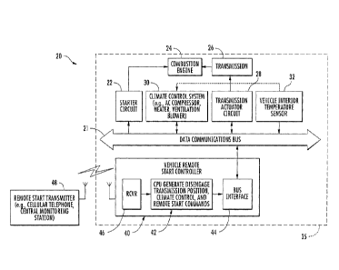
31 [0030] Referring initially to FIG. 1, a remote start control system 20
for a vehicle 35 is now
32 described. The vehicle includes a data communications bus 21 extending
throughout the
33 .. vehicle, an engine 24, and a transmission 26 associated with the engine.
The engine 24 may be
34 a combustion engine, and the transmission 26 may be an automatic
transmission or an
5
22522517.1
CA 02845954 2014-03-14
Blakes Ref: 11053/00002
1 electronically controlled manual transmission. A starter circuit 22 is
coupled to the data
2 communications bus 21 and to the combustion engine for starting the
engine, and may include
3 both a starter and a relay or other controller, such as a powertrain
controller, for staring the
4 engine.
[0031] A transmission actuator circuit 28 is coupled to the data
communications bus 21 and to
6 the transmission 26 for operating the transmission, and may include both
a transmission
7 actuator and a relay or other controller, such as a powertrain or
transmission controller.
8 [0032] The vehicle 35 further includes a vehicle remote climate control
system 30 operable
9 based upon a climate control command on the data communications bus 21.
This vehicle
remote climate control system 30 may include an air conditioning compressor, a
ventilation
11 blower, and/or a heater. The air conditioning compressor may be
mechanically operated via a
12 physical link to the engine (i.e. a belt or shaft), or may be
electrically operated. The ventilation
13 blower is typically electrically operated. The source of heat for the
heater may come from
14 engine waste heat or be electrically generated.
[0033] It should be appreciated that the data communications bus 21 may be a
digital, serial
16 data communications bus, used to multiplex communications between the
various vehicle
17 components. By extending through the vehicle 35, it should be understood
that the data
18 communications bus 21 may physically extend through the vehicle, that
is, such as, through
19 both the passenger compartment and the engine compartment. The data bus
21 may include a
high speed data bus, low speed data bus, or both within the vehicle.
21 [0034] The transmission 26 has a selectable disengaged position based
upon a disengage
22 transmission position command on the data communications bus 21. By
selectable disengaged
23 position, it is meant that the engine 24 is decoupled from the drive
wheels such that the vehicle
24 35 remains stationary while the engine runs. As such, those of skill in
the art will understand
that the selectable disengaged position may be a park or neutral position.
Neutral may be
26 accomplished via the disengagement of a clutch in the transmission from
the engine in the case
27 where the transmission 26 is an electronically controlled manual
transmission, for example.
28 [0035] A vehicle remote start controller 40 includes a receiver 46 at
the vehicle 35. The vehicle
29 remote start controller 40 includes a central processing unit (CPU) 42
or processor coupled to a
bus interface 44. Of course, there may be more than one CPU 42, and/or the
functions may be
31 shared across multiple CPUs. The bus interface 44 of the vehicle remote
start controller 40 is, in
32 turn, coupled to the data communications bus 21 for communications
thereover.
33 [0036] The receiver 46 is for receiving a remote start signal, such as,
from a remote start
34 transmitter 48 to be carried by a user when away from the vehicle 35,
and configured to transmit
6
22522517.1
CA 02845954 2014-03-14
Blakes Ref: 11053/00002
1 the remote start signal. The remote start transmitter 48 may allow for
the sending of different
2 remote start signals that cause the vehicle remote start controller 40 to
output different start
3 commands on the data communications bus 21 that cause the operation of
different vehicle
4 components.
[0037] In other embodiments, the remote start transmitter 48 may be a central
monitoring
6 station communicating over the cellular communications network. The
remote start transmitter
7 48 may also be provided by a cellphone communicating directly with the
vehicle receiver,
8 indirectly with the vehicle receiver via the cellular network, or via a
communication path through
9 a central monitoring station.
[0038] In some embodiments, the remote start transmitter 48 may have a
receiver incorporated
11 therein for two-way communication with the vehicle in some embodiments.
Accordingly, the
12 user may be able to access an internal temperature of the vehicle before
deciding whether to
13 perform a remote start.
14 [0039] The CPU 42, in response to the receiver 46 receiving the remote
start signal, is
configured to generate the disengage transmission position command on the data
16 communications bus 21 to select the disengaged position for the
transmission 26. This causes
17 the transmission actuator circuit 28 to shift the transmission 26 to the
disengaged position. As
18 will be appreciated by those skilled in the art, the disengaged position
may not need to be
19 selected unless the transmission is already in an engaged position.
Accordingly, one or more
sensors, not shown, may supply the state of the transmission to the vehicle
remote start
21 controller 40 in some embodiments.
22 [0040] The CPU 42, in response to the receiver 46 receiving the remote
start signal is also
23 configured to generate the climate control command on the data
communications bus 21 to
24 operate the vehicle climate control system 30. This causes operation of
the air conditioning
compressor, ventilation blower, and/or heater, as will be appreciated by those
of skill in the art.
26 The CPU 42, in response to the receiver 46 receiving the remote start
signal is further
27 configured to start the engine 24 by generating a start signal on the
data communications bus
28 21 for the starter circuit 22 to start the engine.
29 [0041] It should be understood that these functions need not be
performed in the order
described above. For example, the vehicle remote start controller 40, via the
CPU 42, may
31 generate the disengage transmission position command on the data
communications bus 21
32 before generating the climate control command. The CPU 42 may generate
the disengage
33 transmission position command before starting the engine 24, but after
generating the climate
34 control command. Indeed, these commands may be generated in any order
depending on the
7
22522517.1
CA 02845954 2016-02-02
CA 2,845,954
Blakes Ref: 11053/00002
1 application, and the order of command generation may be set by the remote
start transmitter 48
2 or the vehicle remote start controller 40 in some applications. Allowing
the commands to be
3 generated in different orders may allow easier adaption of the remote
start system 20 to
4 different vehicles and different user desires.
[0042] The vehicle 35 may include a vehicle interior temperature sensor 32 in
communication
6 with the vehicle remote start controller 40, such as over the data
communications bus 21. In
7 other embodiments, the temperature sensor 32 may be hardwire connected.
This vehicle
8 interior temperature sensor 32 senses the temperature of the passenger
compartment of the
9 vehicle. The vehicle remote start controller 40 may also generate the
climate control command
on the data communications bus 21 based upon the vehicle interior temperature
sensor 32. For
11 example, the climate control command may activate the air conditioning
compressor if the
12 vehicle interior temperature sensor 32 reports the vehicle interior
temperature is above a
13 threshold, and may activate the heater if the vehicle interior temperate
is below a threshold. In
14 other embodiments, the climate control system 30 may be activated
further based upon an
external temperature sensor, not shown, alone or in combination with the
internal sensor 32.
16 [0043] Those of skill in the art will appreciate that the remote start
system 20 may be multi-
17 vehicle compatible. More details of multi-vehicle compatible devices may
be found in the
18 following references, each of which is assigned to the assignee of the
present invention: U.S.
19 Pat. No. 7,378,945; U.S. Pat. No. 7,369,936; U.S. Pat. No. 7,224,083;
U.S. Pat. No. 7,205,679;
U.S. Pat. No. 7,091,822; U.S. Pat. No. 7,068,153; U.S. Pat. No. 7,046,126;
U.S. Pat. No.
21 7,031,826; U.S. Pat. No. 7,010,402; U.S. Pat. No. 6,812,829; U.S. Pat.
No. 6,756,886; U.S. Pat.
22 No. 6,756,885; U.S. Pat. No. 6,529,124; and U.S. Pat. No. 6,346,876.
23 [0044] With reference to the flowchart 112 shown in FIG. 2, a method of
operating the remote
24 start system is now described. After the start (Block 114), the
disengage transmission position
command is generated on the data communications bus to select the disengaged
position for
26 the transmission, using the vehicle remote start controller and in
response to the remote start
27 signal (Block 116). Then, the engine is started using the vehicle remote
start controller and in
28 response to the remote start signal (Block 118). Thereafter, the climate
control command is
29 generated on the data communications bus to operate the vehicle climate
control system, using
the vehicle remote start controller and also in response to the remote start
signal (Block 120).
31 Block 122 indicates the end of the method.
32 [0045] With reference to FIG. 3, another embodiment of the remote start
control system 20 is
33 now described. The various components shared in common with the remote
start control system
34
8
22866181.1
CA 02845954 2014-03-14
Blakes Ref: 11053/00002
1 20 shown in FIG. 1 operate similarly and need no further description. In
this embodiment, one
2 or more window motors 50' of the vehicle are coupled to the data
communications bus 21',
3 either directly or through an intervening controller, such as the Body
Control Module (BCM).
4 The window motor 50' operates a window of the vehicle 35' (i.e. opens,
closes, partially opens,
partially closes).
6 [0046] In response to receiving the remote start signal via the receiver
46', the vehicle remote
7 start controller 40' and particularly the CPU 42' is configured to
generate the move window
8 command on the data communications bus 21' to cause the window motor 50'
to move the
9 vehicle window. In response to receiving the remote start signal via the
receiver 46', the CPU
42' is also configured to generate the climate control command on the data
communications bus
11 21' to operate the vehicle climate control system 30'. In response to
receiving the remote start
12 signal via the receiver 46', the vehicle remote start controller 40' is
further configured to
13 generate a start command causing the starter circuit 22' to start the
engine 24'. As explained
14 above, the move window command, climate control command, and start
command may be
generated in any order. Moreover, the desired window position may be
programmable upon
16 installation, or selectable upon remote starting as will be appreciated
by those skilled in the art.
17 For example, it may be desirable to slightly open the windows before
starting the air
18 conditioning.
19 [0047] It should be appreciated that the vehicle 35' may have multiple
windows, and that
therefore multiple window motors 50' may be coupled to the data communications
bus 21', and
21 that the vehicle remote start controller 40' may control some or all of
these window motors 50' in
22 the fashion described above. Moreover, these window motors 50' may be
operated
23 independently of each other by the vehicle remote start controller 40'
(i.e. different windows may
24 be operated differently, such that a pair of windows is opened while a
pair of windows remains
closed, for example).
26 [0048] With reference to the flowchart 130 shown in FIG. 4, a method of
operating the remote
27 start system 20' as shown in FIG. 3 is now described. After the start
(Block 132), the engine is
28 started using the vehicle remote start controller and in response to a
remote start signal
29 received by the receiver (Block 134). Thereafter, the move window
command is generated on
the data communications bus to cause the window motor to move the vehicle
window, using the
31 remote start controller (Block 136). Then, a climate control command is
generated on the data
32 communications bus to operate the vehicle climate control system, using
the remote start
33 controller (Block 138). Block 140 indicates the end of the method.
9
22522517.1
CA 02845954 2014-03-14
Blakes Ref: 11053/00002
1 [0049] With reference to the flowchart 142 shown in FIG. 5, another
method of operating the
2 remote start system 20' as shown in FIG. 3 is now described. After the
start (Block 144), the
3 move window command is generated on the data communications bus to cause
the window
4 motor to move the vehicle window, using the remote start controller and
in response to a remote
start signal received by the receiver (Block 146). Then, the engine is started
using the vehicle
6 remote start controller and in response to a remote start signal received
by the receiver (Block
7 148). Thereafter, a climate control command is generated on the data
communications bus to
8 operate the vehicle climate control system, using the remote start
controller (Block 150). Block
9 152 indicates the end of the method.
[0050] With reference to FIG. 6, yet another embodiment of the remote start
system 20" is now
11 described. The various components shared in common with the remote start
control system 20
12 shown in FIG. 1 operate similarly and need no further description. In
this embodiment, a vehicle
13 component actuator circuit 51" that operates a movable vehicle component
52" is coupled to
14 the data communications bus 21". The vehicle component actuator circuit
51" may include the
actuator itself and intervening circuitry or controllers, such as a body
control module. The
16 movable vehicle component 52" may be a vehicle interior component, such
as a seat,
17 telescoping and tilting steering wheel, adjustable pedal(s), or a rear
view mirror actuator. The
18 movable vehicle component 52" may also be a vehicle exterior component,
such as a side view
19 mirror, wiper blade, or trunk latch, etc.
[0051] Here, the vehicle remote start controller 40", and particularly, the
CPU 42", in response
21 to a remote start signal received by the receiver 46", is configured to
generate the movable
22 vehicle component command on the data communications bus 21" to move the
at least one
23 vehicle component actuator 51". The movement of the at least one vehicle
component actuator
24 51" may be based upon personalized settings for the vehicle component
stored at the vehicle,
or by the vehicle remote start controller 40". Alternatively, the movement of
the at least one
26 vehicle component actuator 51" may be based upon input received via the
remote start
27 transmitter 48". The vehicle CPU 42", in response to the remote start
signal, is also configured
28 to generate the climate control command on the data communications bus
21" to operate the
29 vehicle climate control system 30".
[0052] The vehicle remote start controller 40", and particularly, the CPU 42",
in response to the
31 remote start signal, is further configured to generate a start signal on
the data communications
32 bus 21" to cause the start circuit 22" to start the engine 24". As
explained above, it should be
33 understood that the moveable vehicle component command, climate control
command, and
34 start command may be generated in different orders.
22522517.1
CA 02845954 2014-03-14
Blakes Ref: 11053/00002
1 [0053] With reference to the flowchart 160 shown in FIG. 7, a method of
operating the remote
2 starting system 20" shown in FIG. 6 is now described. After the start
(Block 162), the movable
3 vehicle component command is generated on the data communications bus to
thereby move
4 the at least one vehicle component actuator, using the vehicle remote
start controller and in
response to the remote start signal being received by the receiver (Block
164). Thereafter, a
6 climate control command is generated on the data communications bus to
operate the vehicle
7 climate control system, using the remote start controller (Block 166).
Then, the engine is started
8 using the vehicle remote start controller and in response to a remote
start signal received by the
9 receiver (Block 168). Block 170 indicates the end of the method.
[0054] With reference to FIG. 8, a further embodiment of the remote start
system 20" is now
11 described. The various components shared in common with the remote start
control system 20
12 shown in FIG. 1 operate similarly and need no further description. In
this embodiment, the
13 vehicle includes at least one vehicle brake 54", although it should be
appreciated that the
14 vehicle may have one brake per wheel, rendering the number of vehicle
brakes to typically be
four. A vehicle brake circuit 53" is coupled to the vehicle brake 54" for
operating the vehicle
16 brake. The vehicle brake circuit 53" may include a brake actuator and a
braking controller, for
17 example. In other words, the vehicle brake system may of the type
generally described as
18 "brake by wire" where instead of a direct hydraulic circuit operated by
the driver's foot, the
19 driver's foot pressure is sensed and digital controls are used to then
operate the wheel brakes,
or driveline brakes for some vehicles.
21 [0055] Here, the vehicle remote start controller 40" and particularly,
the CPU 42", in response
22 to a remote start signal received by the receiver 46", is configured to
generate the parking
23 brake command on the data communications bus 21" to cause the vehicle
brake circuit 53" to
24 operate the at least one vehicle brake 54". The CPU 42" is further
configured to generate the
climate control command on the data communications bus 21" to operate the
vehicle climate
26 control system 30", in response to the remote start signal. The CPU 42"
is also configured to
27 generate a start signal on the data communications bus 21" to cause the
starter circuit 22" to
28 start the engine 24", in response to the remote start signal. As
explained above, the signals
29 may be generated in different orders.
[0056] It should be appreciated that the vehicle remote start controller 40"
may operate less
31 than all of the vehicle's brakes. For example, the CPU 42" of the
vehicle remote start controller
32 40" may operate a front pair of brakes, or a rear pair of brakes. In
some vehicles, the parking
33 brake function is obtained by use of the rear wheel brakes only.
Moreover, those of skill in the
34 art should recognize that operating the vehicle brake 54" would
typically be engaging the
11
22522517.1
CA 02845954 2014-03-14
Blakes Ref: 11053/00002
1 brake, but in some circumstances it may be desirable to disengage the
parking brake, for
2 example. Whether the brakes are engaged or disengaged could be a
programmable feature, or
3 could be selectable with each remote start selection by the remote
transmitter.
4 [0057] With reference to the flowchart 192 shown in FIG. 9, a method of
operating the remote
start system 20" of FIG. 8 is now described. After the start (Block 194), a
parking brake
6 command is generated on the data communications bus to operate the at
least one vehicle
7 brake, using the vehicle remote start controller and in response to the
remote start signal (Block
8 196). Then, the engine is started using the vehicle remote start
controller and in response to
9 the remote start signal (Block 198). Thereafter, the climate control
command is generated on
the data communications bus to operate the vehicle climate control system,
using the vehicle
11 remote start controller and in response to the remote start signal
(Block 200). Block 202
12 indicates the end of the method.
13 [0058] As will be appreciated by those skilled in the art, the remote
start control system may in
14 the form of one or more housings, including associated circuitry, added
to vehicle after its
original manufacture ¨ in other words, the remote start controller may be
provided by one or
16 more aftermarket components, considered alone or in cooperation with one
or more factory
17 controllers. In other embodiments, the circuitry for the remote start
controller may be provided
18 in the vehicle as part of the original factory assembly. Accordingly,
many modifications and
19 other embodiments of the invention will come to the mind of one skilled
in the art having the
benefit of the teachings presented in the foregoing descriptions and the
associated drawings.
21 Therefore, it is understood that the invention is not to be limited to
the specific embodiments
22 disclosed, and that modifications and embodiments are intended to be
included.
12
22522517.1