Note: Descriptions are shown in the official language in which they were submitted.
54106-1559
- 1 -
BLADE ARRANGEMENT HAVING BLADE CARRIER AND RETAINING GROOVE
FOR BLADES HAVING BLADE ROOT
FIELD OF INVENTION
The invention relates to a blade arrangement.
BACKGROUND
Blade arrangements are known very well from the comprehensive
available prior art. The known blade arrangements are used
both for guide blade, rows and for moving blade rows of
compressors, a circumferential groove for receiving all the
.blades of the row being provided in a blade carrier. The blades
are fastened in the circumferential groove with the aid of a
hammer-shaped or dovetail-like form fit, in . that
correspondingly designed blade roots engage behind projections
protruding from the side walls of the holding groove. In order
to bring about play-free, low-wear and reliable bracing of the
blades in the holding groove, it is known to insert between the
blade root underside and the groove bottom substructures
configured as feather keys, spring elements in the form of a
helical spring or a longitudinally and transversely slotted
clamping sleeve. Mounting and manufacturing plays present in
the radial direction between blade and groove can consequently
be compensated, thus making simple production and mounting
possible. The problem is that the plays in the radial direction
may cause .difficulties in ensuring the tolerances in the
circumferential direction of the groove. It is therefore known
that, in order to set the radial gaps between the airfoil tip
and a duct boundary lying directly opposite the latter, the
profile ends are ground over or brought to size by turning a
lathe, while the blades mounted in the groove are being pressed
outward. Apart from this, there is often the problem of
achieving simple mountability and demountability of blades and
the substructures, along with low production costs.
=
CA 2846053 2018-12-17
CA 02846053 2014-04-07
54106-1559
- 2 -
SUMMARY
The object of some embodiments of the invention, therefore, is
to provide a blade arrangement in which a long-lived and at the
same time reliable and also secure fastening of the blades in
the circumferential groove, along with simple mounting and
demounting, is ensured.
According to some embodiments of the invention, there is provision
whereby each element is of plate-shaped design, has, in the projection
of the airfoil in the direction of the groove bottom, at least one
bead, arranged below the airfoil, for pressing the blade down
in the groove and is covered in the longitudinal direction of
the holding groove only partially by the blade root pressed
down by said element.
With the aid of the element according to some embodiments of the
invention, it is possible for the latter to have an especially
suitable shape which makes a locally resilient substructure possible
and, at another local point, a rigidly acting substructure possible.
Moreover, the element can, on the one hand, be produced
especially simply and, on the other hand, at the same time be
mounted and demounted especially simply. The stiffening action
is generated by a bead or a plurality of beads. Simple
mountability and demountability are achieved in that the
respective element is covered in the longitudinal direction of
the holding groove only partially by the blade root pressed
down by said element. Thus, a portion of the element always
protrudes and can be reached especially simply for a demounting
tool. Furthermore, the plate-shaped geometry of the element
makes it possible to have a space-saving design and blade
arrangement.
The refinement is especially preferred in which a one-part or
multipart intermediate piece is inserted in the holding groove
CA 02846053 2014-02-21
PCT/EP2012/065840 - 2a -
2011P14724W0US
in each case between two blades and is pressed against the
projections by that part of the element which is not covered by
the blade root. In this case, there is an
CA 02846053 2014-02-21
PCT/EP2012/065840 - 3 -
2011P14724WOUS
identical number of blades, intermediate pieces and elements,
the elements having a longitudinal extent which is identical to
the longitudinal extent of the blade root and intermediate
piece. The elements are mounted, offset with respect to
intermediate pieces and blades, so that, as seen in the
longitudinal direction of the holding groove, the element
extends through completely under the blade root and in each
case partially as far as under the two intermediate pieces
adjacent to the blade root. Each intermediate piece is
consequently pressed against the projections of the holding
groove by two elements.
Preferably, the elements are designed in such a way that the
respective intermediate pieces are pressed against the
projections with lower force than the blade root pressed
against the projections by the respective element. In
particular, different rigidities of the element can
consequently be utilized especially advantageously for
different requirements. To be precise, for mounting the
intermediate pieces, a lower spring force of the element is
desirable and is not even required, since, during operation,
there are also no high forces acting on the intermediate piece.
By contrast, the blades firmly clamped in the blade carrier are
exposed during operation to flow forces. This necessitates a
more reliable fastening of the blades to the blade carrier,
thus requiring a higher pressure force. The higher pressure
force is achieved by means of the locally higher rigidity of
the element. This is brought about by the bead or beads
arranged in the element.
In the case of a more rigid underpinning of the blade,
operating principles acting differently can advantageously be
used for mounting and for subsequent operation. On the one
hand, the local material plasticization of the bead is provided
for the compensation of manufacturing tolerances during
mounting. On the other hand, there is provision for utilizing
CA 02846053 2014-02-21
PCT/EP2012/065840 - 3a -
2011P14724WOUS
the residual elasticity in order then to absorb the operating
forces. For this purpose, a material for the element is
advantageously used which is distinguished by a relatively high
ratio of the characteristic numbers for maximum tensile
strength (Rmax) to yield strength (RP0.2)
CA 02846053 2014-02-21
PCT/EP2012/065840 - 4 -
2011P14724W0US
(characteristic number Rmax/Rp0.2 > 1.5), although, in the
choice of material, the yield strength must at the same time
also be sufficiently high for the operating force.
The locally stiffer region of the element is preferably
designed as a bead. The bead is especially advantageously
configured in such a way as to afford a kinked characteristic
curve in the force/path relation. A residual elasticity for
absorbing the operating forces is thereby ensured over a wide
range. This can be achieved by means of a first bead geometry
in which the element has a wall thickness S and the bead has in
cross section a bead width b and also two convex portions with
a radius R2 and a concave portion arranged between them, with a
radius R1, with a chord length A, to which the following
applies:
R1 > 1.5S,
3*R2 > R1 < 0.7R2 and
10b to 1.7b > a.
A second bead geometry with similar properties is achieved if
R1 > 5S, 3*R2 > R1 and a < 0.9b.
A third bead geometry as a combination of the first two bead
geometries with similar properties leads to a twofold bead,
designated as a double bead, which has a further-increased
elastic range.
The beads are preferably established in the element in such a
way that they are arranged below the airfoil in the projection
of the airfoil in the direction of the groove bottom. In other
words, since the elements are established along the
circumferential groove always so as to be offset with respect
to the blades, the beads are basically arranged in the inner
region of the element or at its margin. This enables the
elements to be mounted and demounted in a simple way.
CA 02846053 2014-02-21
PCT/EP2012/065840 - 4a -
2011P14724W0US
Preferably, further, the element has, in its region not covered
by the blade root, at least one orifice.
CA 02846053 2014-02-21
PCT/EP2012/065840 - 5 -
2011P14724W0US
A demounting hook or tool can engage into this orifice in order
to demount said element from its operating position.
Simple mountability of the element can be achieved if a groove
extending along the holding groove is established as a
demounting groove in the groove bottom of the holding groove or
in the blade root underside. During demounting, a sliding
hammer can be applied there comparatively simply, and during
mounting the knocking/pressing in of the element between blade
and groove by means of a ram is simplified.
Expediently, the element has, in the projection of the airfoil
in the direction of the groove bottom (radial axis of vision),
an outer contour which is essentially rectangular. In this
projection, only half the respective element is covered by the
blade pressed down by it. Elements contoured in this way can be
produced especially cost-effectively and simply.
The refinement is especially advantageous in which at least one
longitudinal edge of the element is angled and bears,
prestressed, against the blade roots shaped correspondingly to
it. Insofar as intermediate pieces are used in the blade
arrangement, the angled longitudinal edges may also bear,
prestressed, against the intermediate pieces shaped
correspondingly to it. This refinement makes it possible that
the blades are not oriented solely on the basis of the groove
geometry and the blade root geometry, but are also oriented by
means of the respective adjacent component, be it blade or
intermediate piece. This feature serves for the advantageous
reduction of contact wear.
Advantageously, further, the element has at at least one margin
at least one further bead for local stiffening and for guiding
the element in a guide groove. This further bead at the margin,
preferably the transverse edge, can simplify mounting, since a
CA 02846053 2014-02-21
PCT/EP2012/065840 - 5a -
2011P14724WOUS
ram for knocking/pushing in the element between the blade root
underside
54106-1559
- 6 -
and the groove bottom can be applied at the local stiffening
point, without the element being bent out of shape locally when
subsequently being driven in.
The embodiment is especially preferred in which the bead is
configured as an inner bead which is established in an outer
bead at least partially surrounding the latter. This
embodiment, also designated as a double bead, makes it possible
to have a further increase in the elastic range of the element.
It is likewise conceivable to use threefold beads or even
n-fold beads, in which a corresponding number of beads are
arranged, virtually stacked from inside outward or
hierarchically.
The refinement is especially preferred in which the blade
arrangement is used in an axial-throughflow compressor of a gas
turbine, either for a moving blade ring and/or for a guide
blade ring. This ensures reliable, safe and especially
efficient operation of the gas turbine, since, with this
refinement, the radial gaps between the airfoil tips and the
opposite duct wall of the flow duct of the compressor can be
designed to be especially small.
According to one aspect of the present invention, there is
provided a blade arrangement, comprising: a blade carrier and a
holding groove which is arranged therein and which has on the
blade carrier's side walls longitudinally extending projections
for the formation of undercuts, and in which a number of blades
for forming a blade ring of a turbomachine are inserted, each
blade having in addition to an airfoil, for fastening, a blade
root engaging into the undercuts and being pressed against the
CA 2846053 2018-12-17
54106-1559
- 6a -
projections by a plate-shaped element arranged between a blade
root underside and a groove bottom of the holding groove and
having at least one bead, wherein each element is covered in
the longitudinal direction of the holding groove only partially
by the blade root pressed down by said element and wherein an
intermediate piece is inserted in the holding groove between
two blades and is pressed against the projections by a region
of the element which is not covered by the blade root.
According to another aspect of the present invention, there is
provided an axial compressor for a gas turbine, with a moving
blade ring and/or a guide blade ring designed as a blade
arrangement as described herein.
BRIEF DESCRIPTION OF THE DRAWINGS
The invention is explained in more detail in the following
figure description by means of several exemplary embodiments
which do not restrict the invention. Further features and
further advantages are in this case indicated. In these
figures:
fig. I shows a partial longitudinal section through a gas
turbine,
fig. 2 shows a top view of a detail of a blade arrangement
according to a first refinement,
fig. 3 shows a cross section through the blade arrangement
according to fig. 2 along the sectional line 111-111,
CA 2846053 2018-12-17
CA 02846053 2014-02-21
PCT/EP2012/065840 - 7 -
2011P14724W0US
fig. 4 shows the longitudinal section through the
detail of the blade arrangement according
to fig. 2 along the sectional line IV-IV,
fig. 5, fig. 6 show the cross sections through a blade
arrangement, similar to the sectional line
IV-IV, for a second and a third refinement,
fig. 7 shows a top view of a portion of a blade
arrangement according to a fourth
refinement (without intermediate pieces),
fig. 8, fig. 9 show two variants of the fourth refinement
according to fig. 7 in cross section along
the sectional line
fig. 10 shows a top view of a portion of a blade
arrangement according to a fifth refinement
(without intermediate pieces),
fig. 11, fig. 12 show two variants of the fifth refinement
according to fig. 7 in cross section along
the sectional line
fig. 13 shows a force/elasticity graph,
fig. 14, fig. 15 show the cross section through an element
having different geometries of beads, and
fig. 16 shows the cross section through a bead
geometry in the form of a double bead.
Identical features are given the same reference symbols in the
figures.
CA 02846053 2014-04-07
54106-1559
- 7a -
DETAILED DESCRIPTION
Figure 1 shows a stationary gas turbine 10 in a partial
longitudinal section. The gas turbine 10 has inside it a
CA 02846053 2014-02-21
PCT/EP2012/065840 - 8 -
2011P14724W0US
rotor 14 which is rotationally mounted about an axis of
rotation 12 and which is also designated as a turbine rotor. An
intake casing 16, an axial turbocompressor 18, a toroidal
annular combustion chamber 20 with a plurality of burners 22
arranged rotationally symmetrically to one another, a turbine
unit 24 and an exhaust gas casing 26 succeed one another along
the rotor 14.
The axial turbocompressor 18 comprises an annularly designed
compressor duct with compressor stages succeeding one another
in cascade in the latter and composed of moving blade and guide
blade rings. The moving blades 27 arranged on the rotor 14 lie
with their freely ending airfoil tips 29 opposite an outer duct
wall 42 of the compressor duct. Guide blades 25 likewise
project therein and are secured to the outer duct wall 42 or to
a compressor guide blade carrier. The compressor duct issues
via a compressor outlet diffuser 36 in a plenum 38. Provided in
the latter is the angular combustion chamber 20 with its
combustion space 28 which communicates with an annular hot gas
duct 30 of the turbine unit 24. Four turbine stages 32
connected in series are arranged in the turbine unit 24. A
generator or a working machine (not illustrated in either case)
is coupled to the rotor 14.
When the gas turbine 10 is in operation, the axial
turbocompressor 18 sucks in through the intake casing 16
ambient air 34 as the medium to be compressed and compresses
this ambient air. The compressed air is routed through the
compressor outlet diffuser 36 into the plenum 38, from where it
flows into the burners 22. Fuel also passes via the burners 22
into the combustion space 28. The fuel is burnt there, with the
addition of the compressed air, to form a hot gas M. The hot
gas M subsequently flows into the hot gas duct 30 where it
expands, so as to perform work, at the turbine blades of the
turbine unit 24. The energy meanwhile released is absorbed by
the rotor 14 and is utilized, on the one hand, for driving the
. .
CA 02846053 2014-02-21
PCT/EP2012/065840 - 8a -
2011P14724W0US
axial turbocompressor 18 and, on the other hand, for driving a
working machine or electric generator.
CA 02846053 2014-02-21
PCT/EP2012/065840 - 9 -
2011P14724W0US
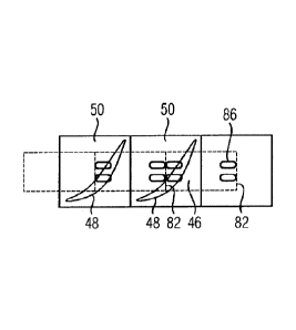
Fig. 2 shows a top view of a detail of a blade arrangement 40
in which only two blades 25, 27 with an intermediate piece 44
established between them and two elements 46 arranged beneath
them are illustrated diagrammatically. The blades 25, 27
comprise a diagrammatically indicated airfoil 48 and also a
blade root 50. The top view is in the radial direction of the
gas turbine 10, that is to say from the airfoil in the
direction of the blade root 50. The blade carrier and a holding
groove arranged in the carrier are not illustrated in fig. 2.
The elements 46 have a rectangular outer contour and are of
plate-shaped design. They are also designated colloquially as
sheet-like. In the first exemplary embodiment (fig. 2), the
blade roots 50 and the blades 25, 27 of the blade arrangement
are arranged obliquely with respect to a longitudinal extent of
the holding groove or of a circumferential direction U. This
positioning is typical of moving blades.
Each element 46 has two beads 52 and in each case two orifices
54. The elements 46 are as long in the circumferential
direction U as the blade root 50 and intermediate piece 44 are
together. However, the elements 46 are arranged centrally below
the respective blade 25, 27, so that two adjacent elements 46
terminate centrally in each case with their opposite ends below
the intermediate pieces 44.
Fig. 3 shows the cross section along the sectional line
through the blade root 50 of the blade 25, 27 and a blade
carrier 56. The airfoil is not illustrated in fig. 3 (nor in
figures 5, 6, 8, 9, 11 and 12). A holding groove 58, in which
the blades 25, 27, in particular the blade roots 50 of the
blades 25, 27, are inserted with a form fit, extends in the
blade carrier 56. To make the form fits, the side walls 60 of
the holding grooves 58 have longitudinally extending
projections 62 so as to form undercuts 64. Correspondingly
formed hammer-shaped root regions 66 engage into the undercut
64.
CA 02846053 2014-02-21
PCT/EP2012/065840 - 10 -
2011P14724W00S
The element 46 is braced between a blade root underside 68 and
a groove bottom 70 of the holding groove 58. Moreover, a
further demounting groove 72 extending along the holding groove
58 is provided in the groove bottom 70. The further groove 72
serves for access for a demounting tool, for example a sliding
hammer.
The wall thickness S of the element 46 (fig. 14) is smaller
than the gap dimension between the blade root underside 68 and
groove bottom 70. The beads 52 produced in the element 46 by
deep-drawing or by pressing in increase the height H of the
element 46 beyond the gap dimension, so that the blade root 50
is pressed against the projections 62. This results in an
unequivocal defined position of the blades 25, 27 in the
holding groove 58.
Fig. 4 shows the longitudinal section through the refinement
according to fig. 2 along the sectional line IV-IV. The
embodiment, illustrated in figs. 2, 3 and 4, of the blade
arrangement 40 is a detail of a moving blade ring of a
compressor 12 of the gas turbine 10. The blade carrier 56 is
accordingly formed by a rotor disk and the blades 25, 27 are
designed as moving blades.
The elements 46 are essentially planar and therefore do not
follow the curvature of the holding groove 58. On account of
this, the elements 46, with their middle region in which the
beads 52 are arranged, press the blade root underside 68 and
groove bottom 70 apart from one another with greater force.
Those portions of the element 46 which are adjacent to the
transverse edges 82, because of the planar configuration of the
elements 46 and the curved holding groove 58, then bear with
lower force resiliently against the undersides of the
intermediate pieces 44. Consequently, the element 46 presses
the intermediate pieces 44 and the blades 25, 27 against the
CA 02846053 2014-02-21
1
PCT/EP2012/065840 - 10a -
2011P14724W0U5
projections 62 of the holding groove 58 with forces of
different magnitude on account of locally different rigidities.
CA 02846053 2014-02-21
PCT/EP2012/065840 - 11 -
2011P14724W0US
A second refinement of a blade arrangement 40 is illustrated in
fig. 5. Fig. 5 shows essentially the cross section according to
fig. 3. In this case, features identical in fig. 5 to fig. 3
are given identical reference symbols. To describe fig. 5,
reference is made as far as possible to the description of fig.
3. According to the second refinement, however, the
longitudinal edges 74 of the element 46 are bent round toward
the groove orifice of the holding groove 58. The bent-round
longitudinal edges 74 (cf. fig. 2) bear, prestressed, against
chamfers 76 arranged on the underside of the blade root. Since
the inteLmediate pieces 44 are designed in a similar way to the
blade roots 50 of the blades 25, 27, those regions of the
longitudinal edges 74 of the element 46 which are established
below the intermediate piece 44 also bear, prestressed, against
corresponding chamfers. The bent-round longitudinal edges 74 of
the element 46 and the prestressed bearing of the elements 46
against the blade roots 50 or Intermediate pieces 44 give rise
to a nonpositive coupling of the adjacent components, namely
the blade root 50 and intermediate piece 44, which improves
their orientation and reduces contact wear between the
components.
A third refinement of a blade arrangement 40 is illustrated
diagrammatically in fig. 6. Fig. 6, too, shows as far as
possible the same cross section as fig. 3, and therefore
features identical in fig. 6 to fig. 3 are given the same
reference symbols. In contrast to the refinement according to
fig. 3, the third refinement according to fig. 6 has on the
blade root underside 68 a comparatively wide groove 78 which,
however, is provided with low depth, and which extends in the
longitudinal direction of the holding groove 58. The groove 78
serves for receiving the element 46, and therefore the groove
depth of the groove 78 corresponds essentially to the wall
thickness S of the element 46. The longitudinal edges 74 of the
element 46 (cf. fig. 2) bear against the inclined side walls of
the groove 78. To the same extent as in the case of the blade
CA 02846053 2014-02-21
PCT/EP2012/065840 - ha -
2011P14724W0US
root 50, according to the third refinement, in the case of the
intermediate pieces 44, a groove 78 arranged on their underside
is also provided, so that the longitudinal edges 74 of the
element 46 also bear against the side walls of the groove 78
arranged on the inteLmediate piece 44.
CA 02846053 2014-02-21
PCT/EP2012/065840 - 12 -
2011P14724W0US
By the elements 46 bearing simultaneously against the blade 25,
27 and the intermediate piece 44, coupling of the adjacent
blade ring components is brought about, thus reducing wear, in
particular contact wear. Both in the second refinement
according to fig. 5 and in the third refinement according to
fig. 6 of the blade arrangement 40 according to the invention,
the blades are designed as moving blades 27.
Figures 8 and 9 show, in a similar way to the cross section
according to fig. 3, a cross section through a blade
arrangement 40 according to a fourth refinement. In contrast to
the abovementioned refinements, the arrangements shown in fig.
7, 8 and 9 are configured as guide blade rings, not as moving
blade rings. The cross-sectional contours of the holding groove
58 and of the blade root 50 differ from one another only
slightly as a result. A further difference from the refinements
described hitherto is that no intermediate pieces 44 are
provided between adjacent guide blades 25. As shown in the
illustration according to fig. 7, therefore, the blades 25 bear
one against the other over their area and without any
positioning of the blade roots 50. In this case, the elements
46 are arranged in each case by half under a pair of adjacent
blades 25. As a result of this, the stiffening beads 52 are
also not established in the inner region in the element 46, but
instead at two opposite transverse edges 82 of the elements 46.
Otherwise, the first variant of the fourth refinement according
to fig. 8 is designed in a similar way to the second refinement
according to fig. 5 with the angled longitudinal edges 74 of
the element 46. A second variant of the fourth refinement,
shown in fig. 9, corresponds structurally essentially to the
third refinement according to fig. 6 in which the element 46 is
for a large part countersunk into a groove 78 arranged on the
blade root underside 68.
CA 02846053 2014-02-21
PCT/EP2012/065840 - 12a -
2011P14724W0US
A fifth refinement of the blade arrangement 40 is illustrated
in a top view according to fig. 10, of which two variants are
shown, a first in cross section in fig. 11 and a second in
54106-1559
- 13 -
cross section in fig. 12. The fifth refinement illustrated in
fig. 10 is based essentially on the first refinement illustrated
in fig. 2. However, in addition to the beads 52 arranged in the
inner region of the element 46, further beads 86 are provided
at the transverse edges 82 in a similar way to the fourth
refinement shown in fig. 7. By the further beads 86 being used
at the margin, the element 46 can reliably be prevented from
bending out of shape or collapsing when it is being driven in
between the blade route underside 68 and groove bottom 70. At
the same time, the further beads 86 engage either into the
demounting groove 72 (fig. 11) or into a groove 78 (fig. 12),
arranged on the underside of the blade root, for the alignment
or guidance of the elements 46.
Figures 14 and 15 show in each case a refinement of the element
46 in cross section along the sectional line from fig.
2. In contrast to the element 46 illustrated in fig. 2, figures
14, 15 illustrate only one bead 52, not two beads 52. Each bead
52 comprises two convexly curved portions X and a concave
portion V arranged between them. The convex portions X have in
each case a radius R2 and the concave portions V a radius Rl.
Moreover, the concave portion V has a chord length a, the bead
52 comprising a bead width b. In order to obtain the bead 52
itself with a region of plastic deformation for a higher load ,
force and a higher spring constant and for a region having
elastic deformation with a low spring constant, two embodiments
of the element are proposed. The first embodiment is achieved
when
R1 > 1.5*S, 3*R2 > R1 > 0.7*R2 and 10*b to 1.7*b > a.
For example, the parameters may have the following dimensions:
R1 - 2 mm; R2 - 2 mm; S = 1 mm; a = 3.5 mm and b = 10 mm.
The second refinement of an element 46 provides for
R1 > 5*S,
3*R2 < R1 and
CA 2846053 2018-12-17
CA 02846053 2014-04-07
54106-1559
- 14
a < 0.9*b.
For example, the parameters may have the following dimensions:
R1 = 20 mm; R2 = 2 mm; S = 1 mm; a - 6 mm and b = 10 mm.
With the aid of the refinement shown, it is possible that the
portion V represents the region of plastic deformation with a
higher load force and higher spring constant and the portions X
represent the regions for elastic deformation with a low spring
constant, as also illustrated in fig. 13.
Fig. 16 shows the cross section through a special bead
geometry. The special bead geometry is a multiple bead 55 in
which an inner bead 55i is surrounded by one or more beads 55a.
The beads 551, 55a of the multiple bead 55 are arranged,
virtually stacked or hierarchically, with a common center M.
The multiple bead 55 shown in fig. 16 is a twofold bead, also
called a double bead. Double beads mean in this case that a
basically concave portion Va of a first (then outer) bead 55a
has established in it a second (then inner) bead 55i. This bead
combination has further-increased elasticity, as compared with
the abovementioned geometries, which may be designated as
single beads, with the result that higher manufacturing
tolerances can be permitted for the blade roots 50, if
appropriate the intermediate pieces 44 and the holding groove
58. Dimensions for the bead geometry according to fig. 16 are
then, for example:
R20 = 20 mm; R1.2 - 2 mm; R2 - 2 mm; ba = 11 mm, aa = hi =
7.4 mm, R3 = 2 mm and ai - 3.2 mm.
Embodiments of the invention relate overall to a blade
arrangement 40 with a blade carrier 56 and with a holding
groove 58 which is arranged therein and which has on its side
walls 60 longitudinally extending projections 62 for the
formation of undercuts 64, and in which a number of blades 25,
27 for forming a blade ring of a turbomachine are inserted,
CA 02846053 2014-02-21
PCT/EP2012/065840 - 15 -
2011P14724WOUS
each blade 25, 27 having in addition to an airfoil 48, for
fastening, a hammer-shaped blade root 50 engaging into the
undercuts 64 and being pressed against the projections 62 by an
element 46 arranged between a blade root underside 68 and a
groove bottom 70 of the holding groove 58. In order to specify
especially secure, reliable, long-lived and low-wear fastening,
which makes especially simple mounting and demounting possible,
there is provision whereby each element 46 is of plate-shaped
design, has, in the projection of the airfoil 48 in the
direction of the groove bottom 70, at least one bead 52,
arranged below the airfoil 48, for pressing down and is covered
in the longitudinal direction of the holding groove 58 only
partially by the blade root 50 pressed down by said element.