Note: Descriptions are shown in the official language in which they were submitted.
CA 02846333 2014-02-24
WO 2013/029591
PCT/DE2012/000859
LIFTING APPARATUS FOR AN AIRCRAFT
The present invention relates to a lifting apparatus
for an aircraft, comprising at least one inflatable
cushion with at least two chambers, at least one
compressor and at least one pressure control device,
wherein each of the chambers is connected to the
compressor via the pressure control device by means of
a hose.
Lifting aircraft by means of lifting apparatuses is
known in the prior art. The lifting of an aircraft with
a lifting apparatus is necessary, in particular, when
the aircraft has to be serviced or if an undesired
operating state of the aircraft, that is to say an
accident, occurs. An undesired operating state occurs,
for example, when an aircraft is in a tilted state
owing to incorrect loading and has to be returned to a
satisfactory position. It may also be the case that
landing gear is not deployed or is damaged during
landing, with the result that the aircraft rests with
its tail or wings on the ground, at least in certain
areas.
In the prior art, various configurations of landing
gear damage are known which require the aircraft to be
lifted at respective different areas of the aircraft.
This may be case, for example, when the front landing
gear of an aircraft has collapsed and therefore the
front area of the aircraft is resting on the ground or
on a runway. Other frequently occurring configurations
are loss or collapse ot one or more main sets of
landing gear, also together with the front landing gear
or landing on an uneven underlying surface beyond a
landing runway which is provided.
Irrespective of the cause of the undesired operating
state of the aircraft, rapid recovery of such aircraft
CA 02846333 2014-02-24
WO 2013/029591 - 2 -
PCT/DE2012/000859
is decisive owing to the high costs of a blocked runway
or a blocked area of an airport. Variable aircraft
lifting apparatuses which can be used in a versatile
fashion are required for recovering aircrafts since the
different types of accident which are described can
occur with a wide variety of aircraft types.
In the prior art it is known, for example, to lift
aircraft by means of what are referred to as "recovery
jacks" - special hydraulic lifting apparatuses which
have to be attached to predetermined points of an
aircraft in order to be able to lift it
(DE 10 2006 007 504 Al).
An example of lifting an aircraft with said recovery
jacks is shown in figure la relating to the prior art.
A plurality of recovery jacks 3, which act at special,
predetermined points (not shown) of the aircraft 1, are
arranged underneath an aircraft 1. In order Lo lift the
aircraft 1 in a controlled fashion, hydraulic
assemblies 4 with a hydraulic pump and with an
integrated control device are provided. The lifting is
regulated by means of the hydraulic assemblies 4 and
the integrated control devices thereof, wherein a power
supply of the hydraulic pumps is made available by a
generator 6. In this context, the recovery jacks 3 are
connected to the hydraulic assemblies 4 by means of
hoses 9.
A disadvantage of the known recovery jacks is that they
have to be kept available individually for an aircraft
type. They are usually available only at specific
airports and often have to be flown into the location
of the aircraft involved in an accident. Lifting with
recovery jacks is therefore often time-consuming and
expensive.
CA 02846333 2014-02-24
WO 2013/029591 - 3 -
PCT/DE2012/000859
With respect to the lifting of aircraft, the prior art
(US 3 160 288 A) also discloses cranes, see figure lb
relating to the prior art. In this context, an aircraft
1 is lifted by means of two cranes 11. In order to be
able to lift the aircraft 1, straps 15, which can
surround the tail of the aircraft, can be arranged on
booms 13 of the cranes 11. The cranes 11 provide the
possibility of being able to lift a multiplicity of
different aircraft types (not shown) since the straps
15 can be arranged on virtually any aircraft type.
However, the lifting of aircraft with cranes is complex
since usually a plurality of cranes have to be
coordinated precisely with one another. Most aircraft
can be lifted completely by a coordinating use of two
to four cranes.
Furthermore, lifting aircraft by means of inflatable
cushions is known in the prior art (DE 27 49 507 Al).
Lifting an aircraft by means of inflatable cushions is
illustrated in figure lc with respect to the prior art.
Figure lc shows an aircraft 1 under which three
inflatable cushions 19 are arranged. Each of the
inflatable cushions 19 comprises here a plurality of
chambers 20, wherein the chambers 20 are each connected
to input devices 5' via hoses 9'. The cushions 19 are
arranged underneath the region 22 of an aircraft which
is to be lifted. The aircraft is lifted by inflating
the cushions 19 or the chambers 20 of the cushions 19.
If necessary, it is additionally possible to provide
for the cushions 19 to be spaced apart from the
underlying surface by means of a substructure 17. The
cushions 19 are always at a predetermined maximum
height in the fully inflated state, with the result
that in the case of relatively large aircraft if
necessary substructures 17 can be arranged under the
cushions 19 in order to reach the required height for
lifting the aircraft. In this context, the cushions 19
. .
. . -
CA 02846333 2014-02-24
WO 2013/029591 - 4 -
PCT/DE2012/000859
are usually inflated by means of a compressor (not
shown).
In order to lift an aircraft with inflatable cushions
it is decisive that they can only be arranged in
specific areas of the aircraft which are predefined by
the manufacturer and that the pressure of the cushion
in the predefined area does not exceed limiting values
predefined by the manufacturer during the lifting of
the aircrart. If the pressure exceeds the predefined
limiting value during the lifting process, damage can
occur to the aircraft. Such damage to aircraft is more
difficult to determine owing to modern materials since
composite materials or the like are being increasingly
used in the construction of aircraft, in which
composite materials an excessively strong force effect
can lead exclusively to damage to the inner structure
of the affected areas, which it is difficult to see, or
cannot be seen, from the outside.
Further lifting apparatuses are known from
DE 34 16 375 Al and WO 2004/087459 which are embodied
as lifting apparatuses, wherein the aircraft can be
transported away after the lifting with these
apparatuses.
The apparatuses from the prior art have here, in
particular, the disadvantage that they are either very
complex, such as the recovery and lifting of aircraft
with cranes, or they require apparatuses which are
individually adapted for each aircraft type, such as in
the case of the recovery jacks. The known inflatable
cushions are, in contrast, cost-effective and very
variable to use. A disadvantage of the inflatable
cushions, is, however, that it is no longer ensured
thai the pressure acts uniformly from the cushion on
the predetermined area of the aircraft. Such uniform
CA 02846333 2014-02-24
WO 2013/029591 - 5 -
PCT/DE2012/000859
pressure, and therefore uniform transmission of force,
is, however, necessary to avoid damage to the aircraft.
The invention is therefore based on the object of
supplying a lifting apparatus for aircraft which
overcomes the disadvantages of the prior art. In
particular, an apparatus is to be made available which
permits controlled transmission of force from a lifting
apparatus with inflatable cushions to predetermined
areas of an aircraft.
This object is achieved in that the lifting apparatus
comprises a pressure-sensitive device with at least two
pressure sensors, and the pressure-sensitive device is
arranged between the uppermost chamber of the cushion
and the area of the aircraft which is to be lifted.
it is also preferred that the lifting apparatus
comprises at least two modules, wherein each of the
modules has at least two chambers and the chambers can
be detachably connected to one another.
According to Lhe invention it is also preferred here
that the pressure sensors of the pressure-sensitive
device, in particular at least one of the pressure
sensors, are/is embodied in such a way that the
pressure sensor or sensors can register a maximum
measured value of 1 bar, preferably at maximum 0.5 bar,
in particular at maximum 0.3 bar, and wherein, in
particular, the pressure sensors of the
pressure-sensitive device are arranged at regular
predetermined intervals, in particular at regular
intervals in a range from 10 cm to 30 cm, wherein the
pressure-sensitive device is preferably composed of a
mat and/or of a film-like material or is introduced
directly into the upper side of the uppermost chamber,
in particular by means of a spraying process or molding
process.
CA 02846333 2014-02-24
WO 2013/029591 - 6 -
PCT/DE2012/000859
It is also possible to provide that each pressure
sensor comprises a pressure-sensitive, piezo-resistive
sensor element, wherein the pressure sensors are
preferably composed of a thin printed circuit, and
wherein the pressure sensors comprise, in particular,
two substrate layers, preferably a substrate layer made
of polyester and a substrate layer made of polyimide.
In particular, it is preferred that the
pressure-sensitive device be composed at least in
certain regions of a compressible material and comprise
at least two magnets or magnetic particles, wherein the
magnets or magnetic particles are moved by compression
or expansion of the pressure-sensitive device, with the
result that a change in the magnetic field which is
generated by the magnets or magnetic particles occurs,
wherein these changes is representative of a change in
the pressure during the lifting of the aircraft.
In this context it is possible to provide that at least
one magnetic sensor be included, for example a Hall
sensor, for measuring the change in the magnetic field,
wherein the magnets or magnetic particles and the
magnetic sensor form, in particular, a pressure sensor,
and wherein the pressure-sensitive device preferably
comprises a foamed mat, wherein the plastic foam
comprises the magnets or magnetic particles and the
magnetic sensor.
In particular, it may prove advantageous that a data
processing device stores measured values of the
pressure-sensitive device, in particular of the
pressure sensors of the pressure-sensitive device, a
current time, a date, a temperature, a user identifier,
an aircraft type and/or further information, wherein
information about characteristic numbers and values of
various aircraft types can preferably be made available
CA 02846333 2014-02-24
WO 2013/029591 - 7 -
PCT/DE2012/000959
by means of the data processing device, and in
particular, the measured values of the pressure-
sensitive device are reconciled with the characteristic
numbers and values.
It is also possible to provide according to the
invention that the uppermost chamber of the lifting
apparatus comprises loose plastic balls, with the
result that the uppermost chamber is adapted to the
contour of the area of the aircraft which is to be
lifted, wherein after the adaptation the air in the
uppermost chamber is substantially removed by means of
a suction pump, with the result that the plastic balls
arc secured by means of the resulting underpressure.
According to the invention it is also preferred that a
substructure is included which spaces apart the
inflatable cushion from the underlying surface.
It is also possible to provide that at least one
chamber of the inflatable cushion, in particular the
uppermost chamber or one of the upper chambers, is
divided into at least two, preferably three, four or
six, partial chambers, wherein compressed air can be
applied to the partial chambers, in each case
separately from one another.
In particular it is preferred that an input device for
actuating the pressure control device is included,
wherein at least two separate pressure control devices
can preferably be actuated with the input device.
It is preferred here that the input device is embodied
as a mobile input device and communicates, in
particular, in a wireless fashion with the pressure
control device or devices.
. . ,
CA 02846333 2014-02-24
MO 2013/029591 - 8 - PCT/D2012/000859
Tt is also possible to provide that a display device is
included which displays at least one representative of
a measured value of at least one pressure sensor of the
pressure-sensitive device, wherein the arrangement of
the displayed representatives of the measured values of
the pressure sensors on the display device preferably
corresponds to the spatial arrangement of the pressure
sensors in the pressure-sensitive device.
According to the invention it is also possible to
provide that an acoustic and/or visual warning signal
is output by means of the display device or a further
output device if a measured value of the pressure
exceeds a predefined maximum permissible value, wherein
the lifting of the aircraft is preferably interrupted
automatically just before the permissible value is
exceeded.
In particular it can prove advantageous that the
representatives of the measured values of the pressure
sensors of the pressure-sensitive device are displayed
in color on the display device, wherein in particular
the measured values are displayed in green, yellow or
red as a function of predetermined measurement ranges.
It is also possible to provide according to the
invention that the position of the pressure-sensitive
device relative Lo the aircraft is displayed on the
display device, in particular the position of all the
pressure-sensitive devices.
According to the invention it is also possible to
provide that the display device is embodied integrally
with the input device, in particular in the form of a
touchscreen, a tablet PC or the like.
Finally, it is also possible to provide that a control
box is included, wherein the control box is arranged
CA 02846333 2014-02-24
1.10 2013/029591 - 9 -
PCT/DE2012/000859
between the compressor and at least one of the lifting
apparatuses, and the control box comprises the pressure
control device, preferably in the form of control
valves, in particular solenoid valves, and wherein the
control box comprises an emergency operator control
device, with the result that the pressure control
device can be operated directly from the control box,
wherein the control box preferably comprises control
software.
The invention is therefore based on the surprising
realization that excessively high pressure during the
lifting of an aircraft can be prevented if a
pressure-sensitive device is arranged between an
uppermost chamber of an inflatable cushion and the area
of the aircraft which is to be lifted. By means of the
pressure-sensitive device, the pressure distribution in
the area of the aircraft which is to be lifted can be
measured directly and displayed to a user, with the
result that controlled lifting of the aircraft is made
possible.
The inflatable cushion can make available large forces,
in particular forces of more than 300 kN, with the
result that it is decisive to transmit the forces made
available by the cushion uniformly to a provided area
of an aircraft. The compressed air which is required by
the lifting apparatus is preferably made available here
by means of one or more compressors.
In order to prevent a maximum permissible pressure at
the area of the aircraft which is to be lifted from
being exceeded, on the one hand the correct
dimensioning of the cushion which is used is decisive
in terms of geometric dimensions, since the pressure
which is applied by the cushion to the aircraft area
during the lifting process is known to be determined by
means of the quotient of the force by the area. On the
_
CA 02846333 2014-02-24
WO 2013/029591 - 10 -
PCT/DE2012/000859
other hand, it is necessary for the cushion to bear
tightly against the contours of the area of the
aircraft which is to be lifted. If the cushion bears
against the tail of the aircraft or of the wings only
in certain areas, a substantially higher pressure is
applied to the aircraft in the areas against which the
cushion bears than is permitted, and the force is
therefore concentrated on specific partial areas of the
area which is to be lifted.
In this context it can be advantageous if the pressure
sensors of the pressure-sensitive device are arranged
at regular intervals. In this context, the pressure
sensors, in particular an individual pressure sensor,
can be configured in such a way that they/it can
register a maximum measured value of 1 bar, preferably
at maximum 0.5 bar, and in particular at maximum 0.3
bar. It has proven advantageous if the pressure sensors
are arranged at a regular interval of 10 to 30 cm and
Form a matrix, wherein the pressure sensors are
distributed uniformly over virtually the entire surface
of thc upper side of the uppermost chamber of the
inflatable cushion. It is therefore possible to ensure
that the force from the cushion is distributed
uniformly over the area of the aircraft which is to be
lifted, and the pressure does not exceed the predefined
limiting values at any time.
For example, a pressure-sensitive device with a length
of 290 cm and a width of 220 cm can be provided which
comprises in total 638 pressure sensors which are
arranged at a regular and identical interval of 10 cm
with respect to one another. It is also possible to
provide that in the case of a pressure-sensitive device
with identical dimensions, 180 pressure sensors are
used, wherein they are arranged at a regular and
identical interval of 20
cm from one another.
Alternatively, it is also possible to provide that in
CA 02846333 2014-02-24
WO 2013/029591 - 11 -
PCT/DE2012/000859
the case of a further pressure-sensitive device with
the dimensions above, 319 pressure sensors are used at
alternating regular intervals of 10 cm and 20 cm. It is
also possible to provide that a pressure-sensitive
device having the dimensions above comprises 158
pressure sensors which are arranged at alternating
regular intervals of 15 cm and 30 cm. A multiplicity of
different forms of arrangement of the pressure sensors
are possible.
It is advantageously possible for the
pressure-sensitive device to be made available in the
form of a mat, a film or the like, wherein the pressure
sensors form an integral component. Such a mat or film
13 can according to the invention also be combined with
existing lifting apparatuses for aircraft which have
not until now had a pressure-sensitive device according
to the invention. Alternatively it is possible to
provide that the pressure-sensitive device is
introduced directly into the upper side of the
uppermost cushion, for example by means of a spraying
process or molding process.
The pressure sensors can advantageously comprise a
pressure-sensitive, piezo-rosistive sensor element,
wherein the pressure sensors can be composed of a thin,
printed circuit. In particular it is possible to
provide that the pressure sensors comprise two
substrate layers, preferably a substrate layer made of
polyester and a substrate layer made of polyimide. As a
result of this design of the pressure sensors it is
possible for the latter to be integrated easily and
cost-effectively into the pressure-sensitive device in
the form of a mat or film or to be introduced directly
into the upper side of the uppermost chamber of the
cushion.
CA 02846333 2014-02-24
WO 2013/029591 - 12 -
PCT/DE2012/000859
Alternatively it is possible to provide that magnets
can be used as a pressure sensor. In this context it is
possible to provide, for example, that small magnets
are introduced into a compressible, pressure-sensitive
device, in particular into a pressure-sensitive device
in the form of a mat or the like. Changing the volume
of the pressure-sensitive device causes the position of
the magnets and therefore the resulting magnetic field
to change. The magnetic field can be detected by means
of a sensor device, for example in the form of a
magnetic sensor (Hall sensor), a coil or the like, and
the change in the magnetic field can be evaluated as
information about a pressure present in the area which
is to be lifted.
Preferred magnets are, for example, super magnets
composed of NdFeB in a wafer format with a wafer
thickness of 0.8-1.5, preferably approximately 1 mm and
a wafer diameter of 5-15, preferably 6-10 mm. They have
an adhesive force in the range from 350-500g, i.e. they
can secure an object up to such a weight given
horizontal orientation of the magnetic wafer. The
remanence B of the magnets is correspondingly in a
range from 1.2-1.5, preferably 1.3-1.4 Tesla (T). The
optimum value of the measuring range of such magnets is
in a measuring distance of the magnet from the sensor
in a range of 8-21 mm, wherein the field strength
decreases logarithmically as the distance increases.
For a super magnet of the thickness 1 mm and of the
diameter of D=6; 8; 10 mm, the magnetic field strength
across the magnet is approximately 1 mT given a
distance of 17; 21; or 25 mm from the sensor, and
approximately 10 mT given a distance of approximately
7; 9; 11 mm, and then increases steeply at even smaller
distances. For this reason, the pressure ratios in the
pressure mat can be determined precisely from the
change in the magnetic field strength.
. .
CA 02846333 2014-02-24
WO 2013/029591 - 13 -
PCT/DE2012/000859
A Hall sensor which has a typical sensitivity of
approximately 5-15, preferably approximately 10 mV/G
(G ¨ gauss, wherein 10 000 gauss correspond to 1 Tesla)
and an output bandwidth of 2-20, preferably
approximately 10 kHz is preferably used as magnet
sensor device. The Hall sensor is usually arranged on a
controller printed circuit board which is embedded in
the foam mentioned below, wherein a magnet is located
in each case at a predetermined distance from the Hall
sensor, thereby forming the pressure sensor, in a
complementary fashion on the side lying opposite the
foam layer.
In this context it is also possible to provide that the
pressure-sensitive device comprises a foam, wherein the
magnets or magnetic particles are introduced into the
foam. As a result, a compressible permanent magnet can
be made available, wherein distribution and the changes
in the magnetic field can be registered by means of
sensor devices. The thickness and compressibility of
the foam layer is selected in such a way that it is at
least 20 mm thick (30 mm thick according to one
preferred example), and is compressed by 6-13 mm,
preferably approximately 7-9 mm, given an overpressure
of 0.5 bar. As a result, a measured value between
1-10 mT and more is generated at the Hall sensor, as a
result of which measurement voltages between 0.1 and
1 V and more can be measured with the above Hall sensor
(sensitivity 10 mV/G).
A pressure-sensitive device can be constructed by
connecting the respective controller printed circuit
board to a centre/ controller and an A/D converter and
a Bluetooth transceiver, with which the measured data
can be forwarded by radio.
A multiplicity of virtual pressure sensors are made
available together with the magnets by the sensor
- - .
CA 02846333 2014-02-24
wo 2013/029591 - 14 -
PCT/DE2012/000859
devices, wherein the sensor devices can be arranged
precisely like the pressure sensors prescribed above.
For uniform transmission of the forces of the lifting
apparatus to the area of the aircraft which is to be
lifted it can be provided according to the invention
that the contour of the lifting apparatus is adapted to
the area which is to be lifted. The need for such
adaptation of a contour becomes clear, for example,
from the fact that a lifting apparatus which is
arranged under a wing of an aircraft has to compensate
for the slope of the wing in order to be able to
transmit the forces uniformly. This occurs, of course,
Lo the same extent for other areas of an aircraft such
as the tail or the nose. In this context it is possible
to provide that the uppermost chamber of the cushion is
filled with a multiplicity of loose plastic balls. Of
course, it is also conceivable that instead of plastic
balls any desired other materials which are suitable
for such contour adaptation are used. These loose
plastic balls can adapt in an optimum way to various
surface contours and therefore permit uniform
transmission of forces of the lifting apparatus.
Alternatively it is, of course, also possible to
provide that contour adaptation is carried out by means
of other devices. Compressed air is not applied to the
uppermost chamber but instead air is removed from the
uppermost chamber by means of a suction pump and an
underpressure is generated. The underpressure fixes the
plastic balls in terms of their shape which is adapted
to the area of the aircraft and causes the plastic
balls to form a fixed structure. Of course, there is
provision that after the termination of a lifting
process the uppermost chamber is filled with air again,
with the result that the plastic balls can be released
from their fixed state.
CA 02846333 2014-02-24
WO 2013/029591 - 15 -
PCT/DE2012/000859
A substructure which is arranged between the ground and
the lifting apparatus can also be provided. Different
aircraft types are of different heights, with the
result that the distance of an area which is to be
lifted from the ground varies. The lifting apparatus
can always only generate maximum lift by inflating the
cushion or the individual chambers of the cushion. If
this lift is not sufficient to lift sufficiently the
area which is to be lifted, a substructure can be used.
The construction of the substructure is variable here.
In this context, the substructure can also be composed
of a further inflatable cushion, wherein, of course, a
multiplicity of further spacing devices for making
available a substructure, such as, for example, a
substructure made of wood or the like, are also
familiar to a person skilled in the art.
In addition to the lifting apparatus bearing tightly
against the area of the aircraft which is to be lifted
it is decisive that the change in the relative position
of the lifting apparatus with respect to the area which
is to be lifted can be taken into account during the
lifting. This change in the relative position results
from a rotation of the aircraft during the lifting
process. Owing to this change in the relative position
of the aircraft with respect to the cushion, an
excessively large force can act on a partial area of
the area of the aircraft which is to be lifted and can
damage it. This results from the fact that the area
which bears against the aircraft is reduced by the
change in the relative position, and correspondingly
the pressure in the areas in which the cushion
continues to bear increases as a result of the constant
force.
In order to compensate for the relative displacement of
the area which is to be lifted with respect to the
lifting apparatus it is possible to provide that at
CA 02846333 2014-02-24
WO 2013/029591 - 16 -
PCT/DB2012/000859
least one chamber of the inflatable cushion, in
particular one of the upper chambers or the uppermost
chamber, is divided into at least two partial areas
which are separated from one another, that is to say
partial chambers. In this context it is possible to
provide that three or six partial chambers are formed,
to each of which compressed air can be applied
separately. This leads to a situation in which the
changing relative position of the lifting apparatus
with respect to the area which is to be lifted can be
compensated during the lifting process in that the lift
of the inflatable cushion is varied by the a different
lift of the partial chambers relative to the area of
the aircraft which is to be lifted.
In particular the pressure-sensitive device according
to the invention is advantageous for such compensation.
The forces and pressures which are applied to the area
of the aircraft which is to be lifted can be displayed
to a user who regulates lifting of the aircraft by
means of an input device, with the result that said
user can actuate the partial chambers selectively.
Through such actuation of the partial chambers, the
lift can be varied and application of the lifting
apparatus is ensured during the entire lifting process.
This is relevant, in particular in practice since, on
the one hand, the user has to maintain a safety
distance from the aircraft owing to a risk of injury
and, on the other hand, precise consideration of the
displacement of the relative position of the lifting
apparatus and area which is to be lifted is difficult
owing to the geometric dimensions of the lifting
apparatus and of the aircraft.
According to the invention it is also possible to
provide that a data processing device is operatively
connected to the lifting apparatus. Owing to technical
insurance requirements, the lifting of an aircraft has
CA 02846333 2014-02-24
WO 2013/029591 - 17 -
PCT/DE2012/000859
to be precisely documented, in particular also the
forces and pressures applied to the area which is to be
lifted. A data processing device according to the
invenLion can store, for example alongside further
data, the measured values of the pressure-sensitive
device, in particular of the individual pressure
sensors of the pressure-sensitive device, a current
time of day, a date, a temperature, an aircraft type
and/or a user identifier. In this context it is also
possible to provide that characteristic numbers and
values of various aircraft types are stored in the data
processing device and the measured values are
reconciled directly with the characteristic numbers and
values.
According to the invention, an input device for
actuating the pressure control device can also be
included, wherein the input device can also be suitable
for actuating two or more pressure control devices.
This may be advanLageous, in particular, when a
plurality of lifting devices are used simultaneously,
with the result that the user does not have to change
between different input devices but instead can perform
all the relevant inputs in a short time by means of an
input device. In this context it may be advantageous,
in particular, if the input device is embodied as a
mobile input device and communicates in a preferably
wireless fashion, for example via WLAN, Bluetooth or
the like, with the pressure control device or devices,
and if appropriate, with further devices of the lifting
apparatus.
It may also be advantageous if the lifting apparatus
comprises a display device which displays at least one
representative of a measured value of at least one
pressure sensor of the pressure-sensitive device. In
this context it can be provided that the order of the
displayed measured values of the pressure sensors on
. .
CA 02846333 2014-02-24
WO 2013/029591 - 18 -
PCT/DE2012/000859
the display device corresponds to the spatial
arrangement of the pressure sensors in the
pressure-sensitive device. For example, each of the
pressure sensors which are arranged in a regular matrix
is displayed as a separate measured value, or a
representative of the measured value, in a matrix which
is displayed on the display device, with the result
that an indication of the pressure in various parts of
the area which is to be lifted is displayed to the
user. As a result, for example through selective
actuation of partial chambers of the inflatable
cushion, the user can correct, even without visual
contact, the relative position of the lifting apparatus
with respect to the area of the aircraft to be lifted,
during the lifting process. Tn practice, this provides
a considerable saving in time and also advantages in
terms of safety.
Tt is also possible to provide that an acoustic and/or
visual warning signal is output by means of the display
device or a further output device if a measured value
of the pressure exceeds a predefined, maximum
permissible value. In this context, for example the
measured pressure values are compared with the maximum
values which are stored in the data processing device
and are specific for a respective aircraft type, and an
effective auxiliary means is therefore made available
to the user, in order to avoid damage to the areas
which are to be lifted. Furthermore, it is also
possible to provide that the lifting of the aircraft is
interrupted automatically just before the permissible
value is exceeded. The maximum permissible value of the
pressure is between 0.1 and 1 bar, preferably between
3.2 and 0.5 bar, and is, in particular, 0.3 bar.
In particular it may be advantageous if the measured
values of the pressure sensors of
the
pressure-sensitive device are displayed in color on the
CA 02846333 2014-02-24
=
WO 2013/029591 - T9 -
PCT/DE2012/000859
display device. In this context, the measured values
can be displayed in green, yellow or red, or of course,
in any other colors, depending on predetermined
measuring ranges. For example, measured values which
lie in a measuring range which is defined as safe can
be displayed in the color green, while measured values
which exceed a predefined limiting value are displayed
in the color red. Furthermore, any desired intermediate
ranges can be defined, these being displayed, for
example, in yellow or orange and being representative
of the predefined limiting values being approached.
It is also possible to provide that the position of the
pressure-sensitive device relative to the aircraft is
displayed on the display device. This permits a user Lo
detect quickly in which partial area of the area which
is lo be lifted it appears appropriate to engage, under
certain circumstances. This may be advantageous, in
particular, when more than one lifting apparatus is
used, with the result that the user quickly detects
what pressure is applied by which lifting apparatus at
the area or areas to be lifted. It can therefore be
particularly advantageous to display the position of
all the pressure-sensitive devices simultaneously, or
if appropriate, sequentially on the display device in a
relative position with respect to the aircraft and the
areas which are to be lifted.
The display device can also be embodied in an
integrated fashion with the inpul device, in particular
in the form of a touchscreen. It can be advantageous
here if a touchpad, tablet PC or the like is used, with
the result that a mobile input and output device is
made available to the user. By means of such a mobile
input and output device, which communicates, in
particular, in a wireless fashion with the further
devices of the lifting apparatus, the user can without
difficulty accompany the lifting of the aircraft from
= CA 02846333 2014-02-24
WO 2013/029591 - 20 -
PCT/DE2012/000859
various positions and have the reIevant areas which are
to be lifted continuously in view.
It is also possible to provide according to the
invention that one or more pressure control devices are
integrated into a control box according to the
invention. A control box according to the invention can
comprise for this purpose, for example, control valves,
in particular solenoid valves. In this context, the
control box can be arranged according to the invention
between a compressor and one or more lifting
apparatuses, with the result that the compressed air
can be fed in a regulated fashion to the individual
chambers of the inflatable cushion of the lifting
apparatus from the compressor via the control box.
Likewise, a reduction in the pressure can be brought
about by means of the control box. An actuation of the
control box is preferably performed here by means of an
input device which is arranged separately from the
control box and which, as already described above, can
communicate with the control box by means of WLAN or
the like.
Furthermore, a control box according to the invention
can comprise the emergency operator control devices,
with the result that the lifting apparatuses can be
controlled directly at the control box even in an
emergency.
A control box according to the invention has a
multiplicity of advantages, wherein reference is made
to the following by way of example. Instead of making
available a multiplicity of separate pressure control
devices, as is customary in the prior art, and
connecting these separately in each case to the
compressor and in each case to an inflaLable cushion,
the control box according to the invention can be
arranged entirely in the vicinity of one or more
. ,
CA 02846333 2014-02-24
WO 2013/029591 - 21 -
PCT/DE2012/000859
cushions because the user controls the lifting process
with the input device which is separate from the
control box. As a result, a considerable quantity of
hose material can be saved because the necessary safety
is made available by means of the separate input device
and, under certain circumstances, only one control box
with a multiplicity of integrated pressure control
devices is then used for a plurality of lifting
apparatuses.
It is also possible to provide that ;.he regulation of
the lifting is assisted, and at least partially
automated, by means of software, for example SPS, which
is integrated in the control box. In this context it is
possible to provide that a comparator is used which
compares setpoint values of the pressure with actual
values and on the basis of this comparison regulates
the pressure in the chambers of the lifting apparatus.
For example, the lifting can be interrupted
automatically just before a permissible maximum
pressure is reached in an area of the area of an
aircraft which is to be lifted.
Further feaLures and advantages of the invention can be
found in the following description in which exemplary
embodiments of the invention are explained by way of
example with reierence to schematic drawings, without
limiting the invention thereto.
In said drawings:
Figure la shows a schematic side view of lifting of an
aircraft with recovery jacks according to the
prior art;
Figure lb shows a perspective view of lifting of an
aircraft with cranes according to the prior
art;
CA 02846333 2014-02-24
WO 2013/029591 - 22 -
PCT/DE2012/000859
Figure lc shows a schematic front view of lifting of an
aircraft by means of inflatable cushions
according to the prior art;
Figure 2 shows a schematic front view of the start of
lifting of an aircraft by means of a lifting
apparatus according to the invention;
Figure 3 shows a schematic front view of lifting of
the aircraft from figure 2 during the lifting
by means of a lifting apparatus according to
the invention;
Figure 4 shows a schematic partial view of lifting of
an aircraft by means of a lifting apparatus
according to the invention, from the front;
Figure 5 shows a schomatic plan view of a
pressure-sensitive device according to the
invention, wherein a detail of the pressure
sensor on a pressure mat is illustrated in
cross section;
Figure 6 shows a schematic plan view of a further
pressure-sensitive device according to the
invention;
Figure 7 shows a schematic partial view of a display
device according to the invention; and
Figure 8 shows a schematic view of a lifting apparatus
according to the invention with a control box
according to the invention.
In the text which follows, lifting of an area 22 of an
aircraft 1 by means of a lifting apparatus 16 according
to the invention for aircraft is described with
reference to figure 2. A lifting apparatus 16 according
to the invention comprises here a first inflatable
cushion 19 which is arranged underneath a first area 22
which is to be lifted, in the example shown underneath
a wing of the aircraft 1. The first cushion 19
comprises at least two chambers 20, 21, wherein the
uppermost chamber 21 can be adapted, in particular, to
CA 02846333 2014-02-24
WO 2013/029591 - 23 -
PCT/DE2012/000859
the contour of the area 22 which is to be lifted. In
order to be able to ensure desired lifting of the
aircraft to a predetermined height, the first cushion
19 is arranged on a first substructure 17, wherein the
first substructure 17 can be made available, for
example, by means of a wooden substructure (now shown)
or in the form of a further inflatable cushion.
Lifting of the aircraft I can be regulated manually
here by means of input devices 5' by opening and
closing compressed air valves, wherein in this
exemplary embodiment, which is to be understood only in
an exemplary fashion, the input devices 5' are
operatively connected directly to hoses 9', with the
result that compressed air, which is made available by
a compressor (not shown) can be applied in a selective
fashion to the cushion 19. According to the invention
it is also provided, in particular, that a mobile input
device (not shown) is used Lo regulate the lifting of
the aircraft 1.
According to the invention, a pressure-sensitive device
(not shown) is arranged between the uppermost chamber
21 of the first cushicn 19 and the first area 22 which
is to be lifted.
In addition to the first lifting apparatus 16 with the
first inflatable cushion 19, two further lifting
apparatuses 16', 16" with inflatable cushions 19',
19" are arranged underneath the aircraft 1. In this
context, the second cushion 19' is also arranged under
the wing of the aircraft 1, and the third cushion 19"
is arranged under the nose of the aircraft 1. The
construction which is illustrated therefore shows the
case of lifting of the aircraft 1 in which both one of
the main sets of landing gear and the front set of
landing gear is damaged.
. .
CA 02846333 2014-02-24
WO 2013/029591 - 24 -
PCT/DE2012/000859
It is obvious here that the position of the areas 22,
22', 22' which are to be lifted is determined as a
function of an aircraft type and the type of lifting.
For uniform transmission of the forces of the cushions
19, 19', 19" to the areas 22, 22', 22" of the
aircraft 1 which are to be lifted it is possible to
adapt the contours of the uppermost chambers 21, 21',
21" of the cushion 19, 19', 19" to the areas 22, 22',
22" which are to be lifted. The need for such contour
adaptation becomes clear, in particular when the third
cushion 19", which is intended to lift a third area
22" at the tail of the aircraft 1, is considered.
Without contour adaptation of the third cushion 19" or
of the uppermost chamber 21" of the cushion 19",
uniform transmission of force to the third area 22"
would not be possible. It is possible to provide here
thal the uppermost chamber 21" of the third cushion
19" is filled with a multiplicity of loose plastic
balls. Of course, it is also conceivable that instead
of plastic balls any other materials which are suitable
for such contour adaptation can be used. Compressed air
is not applied to the uppermost chamber 21" for the
purpose of contour adaptation but instead air is
removed from the uppermost chamber 21", and an
underpressure is generated, by means of an extraction
pump (not shown). The underpressure fixes the plastic
balls in terms of their shape which is adapted to the
area 22' of the aircraft 1 which is to be lifted, and
they form a fixed structure. It is apparent that such
contour adaptation can be provided equally for the
first and second cushions 19, 19'.
Figure 3 shows the aircraft 1 with the lifting
apparatuses 16, 16' according to the invention from
figure 2 during lifting of the aircraft I. During the
lifting of the aircraft 1 it is decisive to take into
account the change in the relative position of the
, .
CA 02846333 2014-02-24
WO 2013/029591 - 25 -
PCT/DE2012/000859
cushions 19, 19' with respect to the areas 22, 22' to
be lifted. Owing to this change .in the relative
position of the aircraft 1 with respect to the cushions
19, 19', an excessively large force can act on partial
areas of the areas 22, 22' of the aircraft which are to
be lifted and damage the latter. Basically, the
displacement of the relative position results here from
a rotational movement of the aircraft 1 during the
lifting. As illustrated in figure 3, the cushions 19,
19' are displaced from a perpendicular position into a
slightly inclined position. If the inclination becomes
too large, it can lead to slipping of the cushions 19,
19', and even make further lifting of the aircraft 1
impossible, wherein, in particular, completely
different pressure conditions can be set over the
entire cushion width. Such different pressure
conditions can be controlled with the pressure-
sensitive device described below.
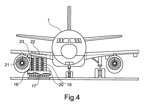
Possible compensation of the relative displacement of
an inflatable cushion 19 cf the lifting apparatus 16
according to the invention from figures 2 and 3 is
shown in figure 4. An uppermost chamber 21 or one of
the upper chambcrs 20 of the cushion 19 are divided
here into at least two partial areas which are separate
from one another, that is to say partial chambers (not
shown). Pressure can be applied separately to each of
the partial chambers (not shown). Selective actuation
of these partial chambers permits the relative
displacement of the cushion 19 with respect to the area
22 to be compensated by adapting the inclination of the
chamber 21 which is divided into at least two partial
chambers, or one of the upper chambers 20 of the
cushion 19. On the one hand, the actuation of the
partial chambers of the cushion 19 can be used to lift
the aircraft 1 safely, and on the other hand, maximum
predefined pressure values in the area 22 which is to
be lifted can be complied with. The pressure is
CA 02846333 2014-02-24
WO 2013/029591 - 26 -
PCT/DE2012/000859
measured here, as already described in the exemplary
embodiments according to figures 2 and 3, by means of a
pressure-sensitive device 23 which is arranged between
the uppermost chamber 21 and the area 22 of the
aircraft 1 which is to be lifted.
Figure 5 shows a schematic plan view of a pressure-
sensitive device 23 according to the invention. The
pressure-sensitive device 23 comprises here a
multiplicity of pressure sensors 25 which are generally
arranged at a predetermined distance 27. In this
context it is possible to provide, in particular, that
the distance 27 is 10 cm.
Figure 5 also shows a detail of a pressure sensor 25 in
cross section which is arranged on a pressure mat 37
composed of a flexible, compressible plastic material,
preferably silicone rubber. The pressure sensor 25 is
composed of a magnet 39 and a Hall sensor 41, which are
each embedded opposite one another in the surfaces of
the pressure mat 37. The Hall sensor 41 is in turn
connected to a transmitting device 43 (for example
Riuetooth circuit board with Bluetooth chip), which is
also embedded in the pressure mat 37. The individual
pressure sensors 25 are connected via lines 45 to a
controller 47, which receives the analog signal and
converts it, by means of an A/D converter, into digital
signals which arc passed onto the transmitting device
43.
Figure 6 shows a further schematic plan view of a
pressure-sensitive device 23 according to the
invention. The pressure-sensitive device 23 also
comprises here a multiplicity of pressure sensors 25
which are generally arranged at a first predetermined
distance 27 and at a second predetermined distance 28
with respect to one another. In this context, the first
predetermined distance 27 can be 30 cm and the second
CA 02846333 2014-02-24
WO 2013/029591 - 27 -
PCT/DE2012/000859
predetermined distance can be 15 cm, with the result
that 28 pressure sensors 25 are used per square meter
of the pressure-sensitive device 23. Of course, various
other arrangements of pressure sensors 25 are also
conceivable.
It can be advantageous here if the lifting apparatus
16, 16', 16" according to the invention in figures 2
to 4 comprises a display device 29 corresponding to the
illustration in figure 7, which display 29 displays at
least the representatives 31, 33 of measured values of
the pressure sensors 25. In this context it is possible
to provide that the arrangement of the pressure sensors
25 which is illustrated in figure 5 corresponds to thc
illustration of the displayed representatives 31, 33 of
the measured values on the display device 29. Such an
illustration of the individual representatives 31, 33
can, for example, assist the user here in deciding
which of the partial chambers of the uppermost chamber
21 or one of the upper chambers 20 has to be actuated
with what lift in order to ensure reliable and defined
lifting of the aircraft 1. In this context, the
representatives 31, 33 of the measured values of the
pressure sensors can be illustrated in color as a
function of predetermined measuring ranges, and when
limiting values are exceeded a warning can be issued.
For example, the representatives 33 signal a high
pressure in a specific partial area in one of the areas
22, 22', 22" which are to be lifted, in figures 2 to
4. As a result, a user can readily recognize what
actuation he has to perform for safe lifting.
It is also possible to provide that the position of the
pressure-sensitive device 23 relative to the aircraft
is displayed on the display device 29 (not shown), with
the result that the user can quickly recognize the
parLial area of the areas to be lifted, for example the
CA 02846333 2014-02-24
WO 2013/029591 - 28 -
PCT/DE2012/000859
areas 22, 22', 22" in figures 2 to 4, in which, under
certain circumstances, engagement appears appropriate.
Figure 8 shows a control box 35 according to the
invention, which control box 35 is operatively
connected to an input device 5, a compressor 7 and a
lifting apparatus 16. The control box 35 comprises here
a pressure control device (not shown) for actuating the
individual chambers of the lifting apparatuses 16. The
control box 35 is for this purpose connected to the
compressor 7 and to the lifting apparatuses 16 by means
of hoses (not shown). The control box 35 can be
actuated by means of the input device 5, which
communicates to the control box 35, for example by
means of WLAN or similar transmitting and receiving
device. Tt is possible to provide here that the control
box 35 comprises control valves, in particular solenoid
valves, and makes available both a positive pressure
for filling the chambers and a negative pressure for
emptying them. Furthermore, it is possible to provide
according to the invention that the control box 35
comprises emergency operator control devices (not
shown) in order also to be able to control the control
valves directly at the control box. The actuation of
the lifting apparatuses 16 which is performed by the
control box 35 is controlled by means of software. In
this context, an SPS controller can be provided for
operating the control box 35.
The use of a control box 35 according to the invention
entails a large number of advantages. A simpler design
of the necessary components for lifting an aircraft can
be made possible because less hose material can be used
than in the prior art. The control box 35 can be
arranged in the vicinity of the lifting apparatuses 16
and nevertheless the necessary safety distance can be
maintained owing to the use of the input device 5 which
is preferably arranged separately from the control box
CA 02846333 2014-02-24
WO 2013/029591 - 29 -
PCT/DE2012/000859
35. In addition, a plurality of lifting apparatuses 16
can be actuated by means of a contro:.. box 35, with the
result that as it were the required quantity of hose
material can be reduced since the control box 35 can
also be positioned in the vicinity of two or more
lifting apparatuses 16. This can save time and
personnel both in terms of construction and operation.
Coordinated operation of a plurality of lifting
apparatuses 16 simultaneously by means of one control
box 35 according to the invention, in particular by
means of the software which is made available in the
control box 35 for controlling the lifting of an
aircraft is also possible.
The features of the invention which are disclosed in
the description above, the claims and the drawings can
be essential to the implementation of the invention in
its various embodiments, either individually or else in
any desired combination.
,
CA 02846333 2014-02-24
WO 2013/029591 - 30 -
PCT/DE2012/000859
List of Reference Numbers
1 Aircraft
3 Recovery jack
4 Hydraulic assembly
5 Input device
6 Generator
7 Compressor
9,9' Hose
11 Crane
13 Boom
Strap
16 Lifting apparatus
17, 17', 17" Substructure
15 19, 19', 19" Cushion
20, 20', 20", 21, 21', 21" Chamber
22, 22', 22'' Area
23 Pressure-sensitive device
Pressure sensor
20 27, 28 Distance
29 Display device
31, 33 Representative
Control box
37 Pressure mat
25 39 Magnet
41 Hall sensor
43 Transmitting device
Line
47 Controller