Note: Descriptions are shown in the official language in which they were submitted.
CA 02846545 2014-03-14
MLP 7693.US
WATER-SHEDDING FLASHINGS
BACKGROUND OF THE INVENTION
Field of the Invention
[0001] This invention relates to an improved flashing for cavity wall
structures. More
specifically the invention relates to water-shedding flashings having a super-
hydrophobic surface
that facilitates drainage within the wall cavity and provides protection
against deterioration of
the structure and against mold and mildew growth. The flashings are designed
to communicate
with the exterior of the cavity wall and operate as a conduit between the
cavity and the channels
throughout the exterior surface of the outer wythe to remove water and water
vapor from the
cavity.
Description of the Prior Art
[0002] In the past, investigations relating to cavity wall flashing
systems for brick
veneer masonry construction have been conducted. While strides have been made
in flashing-
related technologies, including metal foils, embossed channels, polymeric and
elastomeric
materials and hot melt adhesives, there still remain several areas where
continued development
is ongoing.
[0003] The inventors' patents and their assignee's product line are
related to
accessories for cavity wall structures and include masonry flashing,
insulation, and anchoring
and seismic devices, and are sold under the trademarks of Seismiclip , BynaTie
, and DW-10-
X , X-Seal , Foam Tech , and FlexFlashTM. These products, which are
manufactured by
Hohmann & Barnard, Inc., Hauppauge, NY 11788, a unit of MiTek Industries,
Inc., a Berkshire
Hathaway subsidiary, and have become widely accepted in the construction
industry, providing
the inventors with particular insight into the technological needs of this
marketplace.
[0004] Because of widespread usage and familiarity with bituminous and
asphaltic
products in roofing applications, when masonry flashing systems were first
designed, the
building construction industry adopted the familiar copper and asphalt
products. At that time the
technology of pressure-sensitive hot melt adhesives needed for peel-and-stick
applications was
insufficiently developed. Some critics indicated that the tackiness of the non-
asphaltic products
was insufficient for the rough masonry block surfaces.
[0005] Because of the presence of plasticizers, others were apprehensive
about the
available hot melt adhesives meeting the requisite fire retardancy standards.
Also, to provide fire
retardancy, some pressure-sensitive products were marketed for building
construction use with
CA 02846545 2014-03-14
MLP 7693.US
2
inorganic fillers, such as alumina trihydrate, antimony oxide or calcium
carbonate. However,
these filled pressure-sensitive products had disadvantages, such as
application problems, phase
separation, toxicity, and reduced adhesion upon activation.
[0006] The inventors hereof have in inventions related hereto made
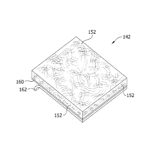
improvements in
the masonry flashing art. Hohmann et al., U.S. Patents 6,584,746 issued July
1, 2003; 6,928,780
issued August 16, 2005; and 6,945,000 issued September 10, 2005; provide
masonry flashing
systems which are suitable either for surface-mounting with a termination bar
or for through-
wall mounting. The devices use state-of-the-art adhesives and various flashing
membranes and
composites.
[0007] Masonry walls with brick veneer are designed with an inner and an
outer
wythe and a cavity therebetween. The backup wall or inner wythe and insulation
thereon isolates
the interior of the building from the environment, and the brick veneer outer
wythe provides an
aesthetic finish to the building and a system of weep holes, channels or
channeled flashing for
removing fluids from the cavity. The inner wythe is constructed to exclude
water and water
vapor from the interior. Where excessive levels of water or water vapor are
present in the cavity,
the deterioration of building materials is hastened. Various masonry flashing
systems in the past
have been adopted to function cooperatively with the system of weep holes and
remove water
and water vapor from within the cavity. However, the nature of the flashing
materials caused
water and water vapor to adhere to the surface, limiting the removal of water
and water vapor
from the cavity.
[0008] The existence of moisture in the cavity hastens the growth of
mold, mildew
and other unwanted infestations within the cavity and causes the weakening of
the physical
integrity of the building materials. Improvements in the thermal insulation of
cavity wall
structures reduces heat exchange between the interior of the building and the
exterior surface.
Such insulation improvements, while conserving energy and lowering HVAC costs,
provides a
more friendly atmosphere for mold, mildew and other unwanted microorganism
infestation
within the cavity. Accordingly, it is essential that water and water vapor be
removed from the
cavity and directed to outside the exterior of the building.
[0009] The present invention focuses on the issue of water removal within
the wall
cavity through the use of specialized coatings and modified surfaces, which
produces a novel
super-hydrophobic surface. The level of water repellency in flashings is
greatly affected not only
by the water repellency characteristics of the materials, but also by the
surface condition. This
ultimate goal of water repellency is achieved by providing a level of super-
hydrophobicity where
CA 02846545 2014-03-14
MLP 7693.US
3
the water contact angle is in the range of at least 120 degrees and preferably
over 150 degrees.
This water contact angle is often referred to as the lotus leaf effect because
the lotus leaf surface
is known to be naturally super-hydrophobic due to the texture of its waxy
surface. This small
contact level inhibits adhesion of the water and water vapor with the
flashings, causing the water
and water vapor to quickly flow down the flashings to the weep holes and
ultimately to the
exterior of the building. The expulsion of water and water vapor from the
cavity removes the
medium for mold and mildew growth.
[0010] In preparing for this application the below-mentioned patents,
some of which
are discussed above, came to the attention of the inventors. The other patents
are believed to be
relevant to the further discussion of the prior art, which follows:
Patent Inventor Issue Date
6,945,000 Hohmann et al. September 20, 2005
6,928,780 Hohmann et al. August 16, 2005
6,584,746 Hohmann et al. July 1, 2003
5,870,864 Snyder February 16, 1999
5,860,259 Laska January 19, 1999
4,910,931 Pardue March 27, 1990
PUBLISHED PATENT APPLICATIONS
Pat.Application Inventor Pub. Date
US 2007/0197717 Ueda et al. August 23, 2007
US 2002/0053300 Beckenhauer May 9, 2002
US 2005/0028455 Koch et al. February 10, 2005
[0011] US Patent 5,870,864 - Snyder - Issued February 16, 1999 Snyder
describes
a drainage system employing water collection pans which for insertion into the
interior cavities
of masonry block units over the length of a selected block wall course for
collecting the water
drained through the interior cavities of the upper courses and directing water
to the exterior of
the wall.
[0012] US Patent 5,860,259 - Laska - issued January 19, 1999 Laska
describes an
insulated drainage panel for use in cavity wall or veneer wall construction
which panel includes
a planar insulating board with a porous structure thereof.
[0013] US Patent 4,910,931 - Pardue - issued March 27, 1990 In the Pardue
patent,
a water collection and drainage system is described for a masonry block wall
having bond beam
block courses and intervening standard block courses. A system of upper water
collection pans is
supported along each upper bond beam course. Downspouts leading from drain
openings in the
CA 02846545 2016-11-23
64725-1271
4
upper collection pans drain collected from the pans through the vertical block
cavities in lower
block courses to the next lower series of collection pans. Weeping spouts lead
laterally from the
base collection pans to the exterior of the wall to continuously drain
collected water from the
interior wall cavities.
[0014] US Patent Application Publication No. 2007/0197717 - Ueda et al. - Pub.
Date August 23, 2007 Ueda details a treating agent containing a fluoropolymer
for use with
masonry. The treating agent imparts water repellency on the masonry and is
applied one or more
times by brushing, spraying, rolling, dipping, or using rags. After
application, the treatment
agent is dried to remove the liquid medium.
[0015] US Patent Application Publication No. 2002/0053300 - Beckenhauer - Pub.
Date May 9, 2002 The Beckenhauer application details methods and compositions
used to
increase water resistance of concrete, masonry or wood building materials. To
achieve water
resistance, a selected amount of an aqueous treating solution is applied to
the material surface.
[0016] US Patent Application No. 2005/0028455 - Koch, et al. - Pub. Date
February 10, 2005 The Koch application describes a combination flashing and
drainage system
that works with a hydrophillic system. The system described uses a layer of
polypropylene or
equivalent as a wicking material to transport water. As wicks are hydrophilic,
water is moved
from wetter to drier areas of the wick and are reversible. The Koch et al.
system relies on
evaporation at the outer exterior edge thereof to reduce the total water
content.
[0017]
SUIV1IVIARY
CA 02846545 2016-11-23
64725-1271
[0018] In one aspect, a water-shedding flashing is sized and shaped to drain
water
away from a building. The flashing comprises an elongate flexible membrane
including a matrix
and hydrophobic material within the matrix. The hydrophobic material within
the matrix is
present at surfaces of the membrane in quantities to reduce surface adhesion
of water on the
elongate flexible membrane.
[0019] In another aspect, a method of making a water-shedding flashing
comprises
providing a matrix material. A hydrophobic material is introduced to the
matrix material. The
matrix material and the hydrophobic material are mixed to form a matrix. An
elongate flexible
membrane sized and shaped to drain water away from a building is extruded from
the matrix to
form a water-shedding flashing having the hydrophobic material present at the
surfaces of the
elongate flexible membrane.
[0020] In general terms, the water-shedding flashing of this invention
provides a
flashing having an elongated membrane with a modified and unmodified surface.
The
unmodified surface is mounted on the exterior of the inner wythe. A pressure-
activated adhesive
is added to the unmodified surface together with a release sheet thereover,
forming a peel-and-
stick assemblage. This facilitates a labor-saving application of the multi-
functional device. The
modified surface is opposite the unmodified surface, facing the cavity, and
conditioned for
adhering with a super-hydrophobic layer. The super-hydrophobic layer is
disposed on the
modified surface and configured to reduce the surface adhesion of water and
water vapor on the
flashing, causing the water to be shed from the flashing and facilitating the
removal of water and
water vapor from the cavity through the channels to the exterior of the outer
wythe.
[0021] The description which follows suggests the best modes and methods of
producing the invention. The invention utilizes a broad range of suitable
methods for
conditioning the modified surface, which include, but are not limited to,
etching, chemical-
vapor-deposition and abrasion.
Similarly, the invention utilizes a broad range of super-
hydrophobic layers, which include, but are not limited to, textured metal
oxides and compounds
with low surface energy. The novel benefits of the water-shedding flashing
include a water
contact angle of at least 120 degrees, causing water and water vapor to bead
and roll down the
surface of the flashing and out to the exterior of the cavity wall structure.
The water-shedding
flashing may optionally be produced as a self-regenerating and self-healing
flashing.
[0022] The water-shedding flashing in the peel-and-stick form includes inter
alia a hot
CA 02846545 2016-11-23
64725-1271
6
melt adhesive. The various embodiments utilize various adaptations of the
basic formulation and
include clear adhesives and adhesives with additives. All the adhesives meet
flammability standards
and are resistive to wide swings in ambient temperatures. This precludes
drooling of the adhesives and
the concomitant marring of exterior wall surfaces. In one embodiment using
creped HDPE, the
adhesive layer is doped with fiber glass or polyethylene fiber fragments. In
applications in which the
water-shedding flashing is adhered to a porous masonry block backup wall, the
tackifier resin content
is optionally increased.
[0023] In some embodiments, there is provided a water-shedding flashing for
draining
water away from a building, the building including a cavity wall structure
having an inner
wythe and an outer wythe, the flashing comprising an elongate flexible
membrane including a
matrix and hydrophobic material within the matrix, the hydrophobic material
within the
matrix being incorporated within the elongate flexible membrane and present at
surfaces of
the membrane in quantities to reduce surface adhesion of water on the elongate
flexible
membrane, the flexible membrane being sized and shaped to drain water away
from the
building and being sized and shaped for installation in the cavity wall
structure with a portion
of the flexible membrane being received in a bed joint of one of the inner
wythe and the outer
wythe thereby facilitating the removal of water from the cavity wall
structure.
[00241 In some embodiments, there is provided a method of making a water-
shedding
flashing comprising: providing a matrix material; introducing a hydrophobic
material to the
matrix material; mixing the matrix material and the hydrophobic material to
form a matrix;
extruding an elongate flexible membrane for draining water away from a
building from the
matrix to form a water-shedding flashing having the hydrophobic material
present at the
surfaces of the elongate flexible membrane, the hydrophobic material within
the matrix being
incorporated within the elongate flexible membrane and the flexible membrane
being sized
and shaped to drain water away from the building and being sized and shaped
for installation
in a cavity wall structure of the building with a portion of the flexible
membrane being
received in a bed joint of one of an inner wythe and an outer wythe thereby
facilitating the
removal of water from the cavity wall structure.
CA 02846545 2016-11-23
64725-1271
6a
[0025]
[0026]
[0027]
[0028]
[0029]
[0030]
CA 02846545 2016-11-23
64725-1271
7
[0031]
BRIEF DESCRIPTION OF THE DRAWINGS
[0032] In the following drawings, the same parts in the various views are
afforded the
same reference designators.
[0033] FIG.1 is a perspective view of a water-shedding flashing of this
invention and
shows a cavity wall with an interior wythe of masonry block and an exterior
wythe of brick
having a through-walled-mounted flashing membrane installed in the cavity
thereof;
[0034] FIG. 2 is a perspective view of a water-shedding flashing of this
invention and
shows a cavity wall with an interior wythe of masonry block and an exterior
wythe of brick
having a surface-mounted flashing membrane installed in the cavity thereof;
[0035] FIG. 3 is a perspective view of the uninstalled water-shedding
flashing of this
invention with the super-hydrophobic layer broken away and an adhesive layer
and release sheet
added thereto;
[0036] FIG. 4 is a top plan view of a chemical-vapor-deposition
surface containing
micro/nano surface morphology of the present invention without the super-
hydrophobic layer;
[0037] FIG. 5 is a perspective view of the water-shedding flashing with water
beaded
on the modified surface; and
[0038] FIG. 6 is a perspective view of a water-shedding flashing of one
embodiment
of this invention formed with a hydrophobic material therein.
DESCRIPTION OF THE PREFERRED EMBODIMENTS
[0039] In the water-shedding flashings of this invention, flexible
membranes are
described that undergo a treatment process to obtain a super-hydrophobic
surface on the
flashings. The super-hydrophobic surface works in cooperation with the
channels in the outer
wythe to shed water and water vapor expeditiously from the wall cavity out to
the exterior of the
building. Removal of the water and water vapor is essential to protect the
structure from water
damage and protect the cavity from mold, mildew or other organic infestations.
[0040] It is well understood that the wettability of various
materials is dependent on
both the physical and chemical heterogeneity of a material. As more fully
described in Nun, et
al., U.S. Patent 7,211,313, Branson, et al., U.S. Patent 7,485,343 and Boris,
et al., U.S. Patent
Application Publication No. 2008/0241512, the notion of using the contact
angle, 0, made by a
CA 02846545 2014-03-14
MLP 7693.US
8
droplet of liquid on a surface of a solid substrate as a quantitative measure
of the wetting ability
of the particular solid has long been well understood. If a liquid spreads
completely across the
surface and forms a film, the contact angle e is 0 degrees. If there is any
degree of beading of
the liquid on the surface of the substrate, the surface is considered to be
non-wetting. For water,
a contact angle of at least 120 degrees, and preferably at least 150 degrees
is considered to be
super-hydrophobic.
[0041] The rolling of liquid droplets and the removal of foreign
particles depend on
both the hydrophobicity of the surface and on the surface roughness caused by
different
microstructures. Super-hydrophobic surfaces may be created by processing an
existing surface.
Typical methods of converting material surfaces to a super-hydrophobic
structure include:
etching the existing surface to create specific nano-patterns and then coating
the surface with a
hydrophobic coating; roughening the substrate surface and then coating the
surface with a
hydrophobic coating; growing a rough film from solutions containing nano-
particles or
polymers, so as to create a rough and hydrophobic surface on the material; and
combining a
rough surface with a surface having a low surface energy.
[0042] The water-shedding ability of the flashings are based on the
mechanisms of
adhesion which are generally the result of surface-energy-related parameters
relating to
interaction of the two surfaces that are in contact. The systems generally
attempt to reduce their
free surface energy. If the free surface energies between two components are
intrinsically very
low, it can generally be assumed that there will be weak adhesion between the
two components.
Where one surface energy is high and one surface energy is low the crucial
factor is very often
the opportunity for interactive effects. Specific to the present invention,
when water is applied
to a super-hydrophobic flashing, it is impossible to bring any noticeable
reduction in surface
energy. The wetting is poor and the water applied forms droplets with a very
high contact angle,
causing the water to fall from the flashing and be directed out to the
exterior surface of the outer
wythe.
[0043] Super-hydrophobic coatings can be applied using numerous methods
which
include, but are not limited to, chemical vapor deposition and coating,
rolling, dipping, spraying,
brushing, and treating with a with a precursor sol comprising a metal
alkoxide, an alcohol, a
basic catalyst, a fluoroalkyl compound and water. Hydrophobic coatings take
varied forms
including rough metal oxide films. The metal oxide films can be any number of
appropriate
compounds containing elements such as titanium, aluminum, zirconium, silicon
or similar. A
coating of titanium dioxide rutile is preferred given its high refractive
indicies and high rate of
CA 02846545 2014-03-14
MLP 7693.US
9
dispersion.
[0044] The water-shedding flashings are formulated to be self-healing and
self-
regenerative. The self-healing and self-regenerative features are achieved
through the use of
layers of particles typically from the group consisting of silicates, doped
silicates, minerals,
metal oxides, silicas, polymers, and silica-coated metal powders. These
particles are secured on
a carrier consisting of particles and a binder. When the surface particles are
ablated, new
particles from the carrier are exposed and regenerate the super-hydrophobic
surface. To allow
self-regeneration, it is necessary for there to be differences in the
properties of the material used
for the particles and for the binder. When a particle is lost, new particles
come to prominence
from the binder and replace those lost.
[0045] To assist in installing the water-shedding flashing on the
exterior surface of the
inner wythe, pressure-activated adhesives and release sheets are added to the
water-shedding
flashings on the installation side of the flashings thereby forming peel-and-
stick assemblages,
which assemblages enable surface- and through-wall-mounting with a substantial
saving of
labor. The adhesives employed are state-of-the-art, clear, hot-melt adhesives
with formulations
that are highly adaptable to the various field uses. Exemplary of the
adaptability is that the
tackiness of the hot melt adhesive formulation employed is adequate for
flashing installation on
drywall and on masonry block. Further, when a fibrous material is added to the
adhesive to
strengthen the overall construct, the tackifier additive is increased to
retain the bonding
characteristic.
[0046] Referring now to FIGS. 1-5, this embodiment of the invention in
which a
water-shedding flashing assembly or masonry flashing structure referred to
generally by the
reference designator 10 is shown. In this embodiment, a cavity wall structure
12 is shown having
an inner wythe 14 of masonry blocks 16 and an outer wythe 18 of facing brick
20. Although an
inner wythe 14 of masonry blocks 16 is shown, the water-shedding flashings of
this invention
may be applied to alternative materials such as, a drywall inner wythe (not
shown). Between the
inner wythe 14 and the outer wythe 18, a cavity 22 is formed. Optionally,
insulation 44 may be
installed. Successive bed joints 24 and 26 are formed between courses of
blocks 16 and the
joints are substantially planar and horizontally disposed. Also, successive
bed joints 28 and 30
are formed between courses of bricks 20 and the joints are substantially
planar and horizontally
disposed. For the through-wall-mounted flashing installation of this
embodiment (FIG. 1), the
flashing 42 is shown extending into bed joint 26 of the inner wythe 14 and
into bed joint 28 of
the outer wythe 18. For the surface-mounted flashing installation, as shown in
FIG. 2, the
CA 02846545 2016-11-23
64725-1271
installation includes the use of a termination bar 45.
[0047] For
purposes of this discussion, the exterior surface 33 of the outer wythe 18
contains a horizontal line or x-axis 34 and an intersecting vertical line or y-
axis 36. A horizontal
line or z-axis 38 also passes through the coordinate origin formed by the
intersecting x- and y-
axes. A horizontal line or z-axis 38 also passes through the coordinate origin
formed by the
intersecting x- and y-axes. In the discussion which follows, it will be seen
that the water-
shedding flashing 42 of this invention is constructed to work in conjunction
with the channels or
weep holes 40 and optionally a drip edge 46 in the outer wythe 18 to drain
water from the cavity
22. Alternatively, the flashing is channeled or embossed, removing the need
for weep holes or
exterior wythe channels (not shown). The channels permit air and water to exit
the cavity while
providing ventilation to the cavity. Removal of water and water vapor is
essential to the
integrity of the structure and protection against the growth of mold, mildew
and other organic
infestations.
[0048] Referring now to FIG. 3, a perspective view of the water-shedding
masonry
flashing 10 is shown. An elongated flexible membrane 42 is shown and is
constructed from a
sheet of laminate material in the 10- to 100-mil range or similar materials.
While the
membranes hereof are described as consisting of stainless steel, zinc, copper,
polyvinyl chloride,
ethylene propylene diene monomer, recycled rubber, Elvaloy, low density
polyethylene, high
density polyethylene, polyethylene teraphalate, polypropylene, styrene
isoprene styrene, styrene
ethylene butadiene styrene, styrene ethylene propylene, and admixtures thereof
other flexible
materials, which might fall outside this classification may be used.
[0049] As seen in FIGS. 3 through 5, the water-shedding flashing 42 has a
modified
surface 48 and an unmodified surface 50. The modified surface is conditioned
to reduce surface
adhesion of water and water vapor and to receive a super-hydrophobic layer 52.
The surface is
conditioned by etching (not shown), using a chemical-vapor-deposit on the
surface, abrading the
surface (not shown), or through similar methods to create a textured surface.
The chemically-
vapor-deposited surface 54 consists of micro/nano particles 56 and is shown in
FIGS. 3 and 4.
Disposed atop the modified surface 48 is a super-hydrophobic layer 52. The
super-hydrophobic
layer 52 is preferably a textured titanium dioxide ruffle film, although other
textured metal oxide
films such as titanium oxides, aluminum oxides, zirconium oxides, silicon
oxides and similar are
effective. Further, other super-hydrophobic precursor sols may be substituted.
[0050] As shown in FIG. 5, the modified surface 48 with a super-hydrophobic
coating 52 causes water 54 to bead upon contact when in a horizontal form.
Upon installation in
CA 02846545 2016-11-23
64725-1271
11
a vertical manner, the water-shedding flashing 42 prevents the water and water
vapor 54 from
adhering to the flashing 42 thereby forcing the water to flow down the
flashing 42 and be
directed to the exterior surface 33 of the outer wythe 18 through the channels
40. Continual
flow through the channels 40 prevents blockages in the channels 40. The water-
shedding
flashing 42 can be optionally made self-regenerative and self-healing (not
shown).
[0051] Referring again to FIG. 3, the water-shedding masonry flashing 42 is
shown as
a peel-and-stick product and further includes an adhesive layer 60 which is
formulated for
pressure activation and compatibility with the flashing membrane or web 42 and
the release
sheet 62 adhered thereto. The adhesives described herein include, but are not
limited to
bitumen, clear, and hot melt adhesives. The preferred hot melt adhesives
described herein are
particularly useful for peel-and-stick applications in building construction
industry as such
adhesives are readily pressure activated after the release paper is removed.
Alternatively, the
flashing is produced without the included adhesive layer for installation on-
site with separate
adhesives or by other methods of installation (not shown).
[0052] The adhesive is formulated so that, in case of fire, the
coatings thereof will not
contribute to smoke or accelerate flame spreading. The adhesive layer 60
optionally includes an
inorganic material, namely, an alkali-resistant fiber glass. This additive
enhances the overall
strength of the flashing system and provides multidirectional reinforcement.
Alternative to being
doped with the fiber glass additive, the flashing may be strengthened using
polymeric fiber
fragments. Also, the fiber-doped adhesive layer is formulated to have
sufficient tackiness so that
a durable bond between the membrane and the rough and porous surface of the
masonry block is
experienced. The adhesive on the flashing permits butting of the widths of
flashing precluding
the use of caulks and sealants at the joints. The joints can be further
reinforced with sealing tape.
[0053] Referring to the Di Rado et al. patent, U.S. Patent 5,106,447,
the
hot melt adhesive compositions of hot melt layer 60 may be prepared from 10 to
50 weight
percent of a thermoplastic elastomer, namely, thermoplastic polybutene-
1/ethylene copolymer
containing from about 5.5 to about 10% by weight ethylene (polybutylene); 20
to 50 percent of a
tackifier; 15 to 50 percent of an amorphous diluent having a softening point
greater than 90
degrees C.; and, 0 to 2 percent of a stabilizer.
[0054] The polybutylene copolymers employed herein are copolymers of
polybutene-1
and ethylene wherein the ethylene content varies from about 5.5 to about 10%
weight of the
copolymer. The applicable isotactic polybutylenes are relatively rigid while
in their plastic form
but flow readily upon being heated. Expressing molecular weight in terms of
melt index, the
CA 02846545 2016-11-23
64725-1271
12
applicable isotactic polybutylenes to be used in the present adhesive should
exhibit a melt index
in the range of from about 5 to 2000 dg/min and preferably from 400 to 700
dg/min. The latter
melt flow values are determined by the method described in ASTM D1238 and are
inversely
related to molecular weight, i.e., the lower the melt index, the higher the
molecular weight.
These copolymers are available from Shell Chemical Company under the Duraflex
trademark as
Duraflex 8310, 8410, 8510, and 8910, with the 8910 having a melt index of
about 700, a grade
preferred for use herein. Mixtures of these copolymers may also be used.
[0055] The tackifying resins which may be used to extend the adhesive
properties of
the isotactic polybutylene include: (1) hydrogenated wood rosin or rosin
ester; (2) polyterpene
resins; (3) aliphatic petroleum hydrocarbon resins; and, (4) partially and
fully hydrogenated
hydrocarbon resins.
[0056] The polyterpene resins have a softening point, as determined by an ASTM
method E28-58 T, of from about 80 degrees C. To 150 degrees C., the latter
polyterpene resins
generally resulting from the polymerization of terpene hydrocarbons in the
presence of Friedel-
Crafts catalysts at moderately low temperatures and including the latter
resins which are
aromatically modified; examples of commercially available resins of this type
being the Nirez
resins sold by Reichhold Chemical, the Zonatac resins sold by Arizona, and the
Piccolyte S-10,
S-25, S-40, S-85, S-100, S-115, S-125 and S-135 resins as sold by Hercules
Chemical.
[0057] The aliphatic petroleum hydrocarbon resins have a Ball and ring
softening
point of from about 80 degrees C. To 160 degrees C., resulting from polymer-
ization of
monomers consisting primarily of 5 carbon atom olefins and diolefins, and
including the latter
resins which are aromatically modified, examples of commercially available
resins of this type
being Wingtack 95 and Wingtack Extra as sold by the Goodyear Tire and Rubber
Company and
the Escorez 1000 series of resins sold by the Exxon Chemical Corporation.
[0058] Examples of the partially and fully hydrogenated hydrocarbon resins are
resins
such as Resin H-130 from Eastman, Escorez 5000 series from Exxon, and Regalrez
from
Hercules. The amorphous diluents which are needed and present in the adhesive
composition
include (atactic) amorphous polypropylene or other similar high softening
point (i.e. greater than
90 degrees C.), low crystalline diluent, (e.g. amorphous polyalpha-olefins).
These diluents, are
used at levels of 20 to 50% by weight, preferable about 20 to 25% by weight.
[0059] A suitable release paper is applied thereover. After a
prescribed cure period,
the release paper 62 is removed and the flashing of this invention is applied
to the inner wythe
14. The application to the inner wythe is at room temperature utilizing a hand-
operated
CA 02846545 2014-03-14
MLP 7693.US
13
laminating roller to provide the pressure activation. A spring scale is then
attached to the
masonry flashing and a 65 lb. force is required to peel the flashing from the
block. Repeating the
test for SBS-modified, peel-and-stick flashing, a force of 27 lb. (max.) Is
required to peel the
flashing from the block.
[0060] Among the applicable stabilizers or antioxidants utilized herein
are included
high molecular weight hindered phenols and multifunctional phenols such as
sulfur and
phosphorous-containing phenols. Representative hindered phenols include: 1,3,5-
trimethyl 2,4,6-
tris (3,5-di-tert- butyl-4-hydroxy- benzyl)benzene; penta-erythrityl tetrakis-
3 (3,5-di-tert-buty1-
4-hydroxyphenyl) pro-pionate; 4,4'methylenbis(2,6-tert-butyl-phenol); 4,4'-
thiobis (6-tert-butyl-
o-cresol); 2,6-di-tertbutylphenol; 6-(4-hydroxy-phenoxy)-2,4-bis(n-octyl-thio)-
1,3,5-triazine; di-
n-octadecyl 3, 5-di-tert-butyl-4-hydroxy-benzylphosphonate; 2-(n-octylthio)-
ethyl 3,5-di-tert-
buty1-4-hydroxybenzoate; and sorbitol hexa [3- (3,5-di-tert-buty1-4-
hydroxypheny1)-propionate].
[0061] The performance of these antioxidants may be further enhanced by
utilizing, in
conjunction therewith known synergists such, for example, as thiodipropionate
esters and
phosphites. Particularly useful is distearylthiodipropionate. These
stabilizers are generally
present in amounts of about up to 2 weight percent, preferably 0.25 to 1.0%.
Besides the glass
fiber reinforcing agent mentioned above, other additives such as flow
modifiers, pigments,
dyestuffs, etc., which are conventionally added to hot melt adhesives for
various end uses may
also be incorporated in minor amounts into the formulations of the present
invention.
[0062] The water-shedding flashing 42 is produced as follows:
(a) providing a membrane 64 having two major surfaces 48, 50, for use in a
cavity
wall 12;
(b) modifying one of said two major surfaces 48, 50 for the purpose of
accepting a
super-hydrophobic layer 52 thereon;
[0063] The production of the water-shedding flashing 42 further comprises
one of the
following alternative substeps:
(b)(1) etching said modified surface 48;
(b)(2) providing a chemical-vapor-deposited composition 54 on said modified
surface
48;
(b)(3) abrading said modified surface 48; or
(b)(4) growing a rough film from a nano-particle solution on said modified
surface 48.
(e) adhering a super-hydrophobic layer 52 on said modified surface 48.
[0064] Optionally, the water-shedding flashing 42 further comprises the
steps of:
CA 02846545 2014-03-14
MLP 7693.US
14
(d) applying an adhesive layer 60 on said unmodified surface 50; and,
(e) disposing a release sheet 62 on said adhesive layer 60, said release sheet
62 being
removable prior to mounting said flashing 42 in said cavity 22 of said cavity
wall 12.
100651 The water-shedding flashing 42 installation is completed by:
(f) disposing said flashing 42 on the exterior surface 35 of said inner wythe
14 in
communication with said channels 40 of said exterior surface 33 of said outer
wythe 18.
[0066] The water-shedding flashings of this invention enable the erector
of a cavity
wall to provide a very low moisture cavity wall that reduces material
deterioration and removes
residual moisture, thereby removing the medium for mold, mildew and other
organic
infestations. Because of the nature of the prior art flashing materials, water
and water vapor
removal was limited. This improved novel cavity wall flashing provides a super-
hydrophobic
surface that facilitates drainage within the wall cavity.
[0067] The flashings are designed to communicate with the exterior of the
cavity wall
and operate as a conduit between the cavity and the channels throughout the
exterior surface of
the outer wythe to remove water and water vapor from the cavity. The existence
of moisture in
the cavity hastens the growth of mold, mildew and other unwanted infestations
within the cavity
and causes the weakening of the physical integrity of the building materials.
Improvements in
the thermal insulation of cavity wall structures reduces heat exchange between
the interior of the
building and the exterior surface. Such insulation improvements, while
conserving energy and
lowering HVAC costs, provides a more friendly atmosphere for mold, mildew and
other
unwanted microorganism infestation within the cavity. Accordingly, it is
essential that water
and water vapor be removed from the cavity and directed to outside the
exterior of the building.
[0068] The present invention focuses on the use of specialized coatings
and modified
surfaces, which produces a novel super-hydrophobic surface. Such novel
flashings provide a
water contact angle in the range of at least 120 degrees and preferably over
150 degrees. Such a
high water contact angle causes water and water vapor to roll off the flashing
and out to the
exterior of the outer wythe, thereby solving the prior art issue of residual
moisture in the cavity.
[0069] As an alternative to adhering a super-hydrophobic layer to the
flexible
membrane, a membrane 142 can instead be formed from a compound containing
hydrophobic
and/or super-hydrophobic materials (see Figure 6). The flashing 142 can be
extruded from a
master batch containing both resin pellets and compounds with hydrophobic
properties, such as
metal oxides including titanium dioxide rutile, titanium oxides, aluminum
oxides, zirconium
oxides, silicon oxides, or similar. Any suitable chemical compound that
creates a hydrophobic
CA 02846545 2016-11-23
64725-1271
or super-hydrophobic surface or alters the property of a substance to which it
has been added to
promote the shedding of water and prevent water molecules from attaching to a
surface can be
used within the scope of the present invention. The resin matrix can be any
material described
above as suitable for forming the flashing 42, such as polyvinyl chloride,
ethylene propylene
1t),
diene monomer, recycled rubber, Elvaloy, low density polyethylene, high
density polyethylene,
polyethylene teraphalate, polypropylene, styrene isoprene styrene, styrene
ethylene butadiene
styrene, styrene ethylene propylene, and admixtures thereof, or any other
suitable flexible
materials. The hydrophobic compounds and the resin pellets can be added to the
extruder by a
volumetric, gravimetric multi-component feeder, as is known in the art. In one
embodiment, the
master batch used to form the water shedding flashings 142 is approximately
50% to 90 % resin
and approximately 10 % to 50% hydrophobic additive. The master batch
containing the resin
and the hydrophobic additive is thoroughly mixed during the extrusion process,
resulting in a
substantially uniform composite forming the flashing 142 with hydrophobic
qualities.
[0070] Alternatively, the hydrophobic compound can be introduced in a liquid
state
further along the extruder barrel by a melt pump injector. In this process,
the hydrophobic
additive is mixed in with the resin later in the extrusion process. There must
be sufficient
mixing downstream of the injection port so that the hydrophobic additive is
fully mixed into the
resin, resulting in a substantially uniform composite forming the flashing
with hydrophobic
qualities.
[0071] As described above with reference to the previous embodiments, the
water-
shedding masonry flashing 142 can be a peel-and-stick product and further
includes an adhesive
layer 160 which is formulated for pressure activation and compatibility with
the flashing
membrane or web 142 and the release sheet 162 adhered thereto. The adhesive
layer can be the
same as described above, and as such will not be described again.
[0072] The water shedding flashing 142 formed from resin with a hydrophobic
additive, whether the additive is mixed with the resin at the beginning of the
extrusion process or
later in the extrusion process, exhibits the same hydrophobic qualities as the
water shedding
flashing 42 having a super-hydrophobic layer adhered to a surface of the
flashing. Because the
hydrophobic and super-hydrophobic materials are added into the resin used to
form the flashing
142 and do not simply coat a single surface of the flashing, the flashing may
offer better
hydrophobic qualities. Every surface 152 of the flashing 142 can have
hydrophobic or super-
hydrophobic qualities. As described above with reference to flashing 42, the
flashing 142 causes
water to bead upon contact and prevents the water and water vapor from
adhering to the
CA 02846545 2014-03-14
MLP 7693.US
16
flashing. The water is thereby forced to flow down the flashing 142 and be
directed to the
exterior surface of the outer wythe through the channels or weep holes.
[0073] In the
above embodiments, the best modes of practicing this invention have
been described. While the examples are specific as to the water-shedding
flashings employed,
variations can be made without departing from the spirit of the invention.