Note: Descriptions are shown in the official language in which they were submitted.
CA 02846634 2014-02-25
WO 2013/033215 PCT/US2012/052864
DEPLOYMENT OF STENTS WITHIN BIFURCATED VESSELS
CROSS-REFERENCE TO RELATED APPLICATIONS
100011 This specification claims the benefit of the filing date of U.S.
Provisional
Patent Application No. 61;528,968, which is titled "Systcms and Methods for
Deploying
Stents within Bifurcated Blood Vessels" and was filed on August 30, 2011, the
disclosure of
which is hereby incorporated by reference herein in its entirety.
TECHNICAL FIELD
[0002] This specification relates generally to systems and methods for
stent
deployment, and, more particularly, to systems and methods for deploying
stents within
bifurcated vessels.
BACKGROUND
[0003] Bifurcation occurs when a vessel (or main branch) splits into two
separate
blood vessels (or side branches). Typically, the two side branches are smaller
than the main
branch. In the case of blood vessels, plaque buildup in the bifurcated region
may cause
stenosis or otherwise compromise blood flow. These types of lesions may occur
within the
main branch as well as in the side branches.
[0004] Over the years, a few techniques have been developed to attempt to
treat
lesions at bifurcations. An example of a bifurcation stent delivery device is
described in U.S.
Patent Application Publication No. 2005/0209673 (Snaked). Specifically,
Shaked's device
uses an additional lumen to accommodate a secondary guide wire that is
inserted into a side
branch at a bifurcation. The inventor hereof has recognized, however, that the
exit point for
the secondary guide wire occurs at the midpoint of the device. As a result,
the struts from the
exit point may get incorrectly aligned, which may hinder the deployment of a
side branch
stent.
[0005] Another bifurcation device is disclosed in U.S. Patent No. 7,686,845
(Sequin).
Sequin's device uses a self-expanding stent, which the inventor hereof has
also recognized
tends to be difficult to maneuver and deploy, especially if the plaque burden
in the vessel is
high. Moreover, the struts of Sequin's stent are subject to grabbing on to
plaque during
CA 02846634 2014-02-25
WO 2013/033215 PCT/US2012/052864
2
deployment, which may result in inaccurate placement of the stent, damage to
the vessel,
plaque shift, dissection, or even plaque embolization.
SUMMARY
[0006] The currently existing limiting factors for bifurcation stenting can
be
overcome by novel techniques described herein, which: a) accurately identify
the location of
the carina in two dimensional angiographic views, b) accurately position the
stents at the
carina, c) accurately deploy the stents in relation to the carina, d) position
wires in the main
lumen and the side branches without going through stent struts, e) cover the
entire area of the
bifurcation so as to get a smooth luminal outcome initially without plaque
protruding within
the lumen (e.g., 100% coverage of the area is particularly important to obtain
the anti-
restenosis benefit of drug eluting stents), f) avoid stent struts from
protruding within the
lumen where blood flows ¨ a problem associated with stent thrombosis, g) allow
for
reintervention in the future to treat new lesions distally or restenosis of
the bifurcation
without being hindered by the previously deployed bifurcation stents (e.g.,
the absence of
jailed side branches provides natural anatomic side branch access later), h)
allows for
completion of a bifurcation stenting procedure with predictable, timely
success without
complications in the hands of competent operators with common and adequate
skills, i) result
in low radiation and limited contrast use, j) avoid the need for bypass
surgery as the first
option or as a complication of the procedure, k) use available (albeit off-
label) stent
technology to achieve successful results, and I) creates the possibility that
industry can adapt
these changes without the need to invent new stents, but instead by
modification of existing
balloons and channels.
[0007] Systems and methods for accurately deploying stents within
bifurcated vessels
are disclosed. In an illustrative, non-limiting embodiment, a method may
include inserting a
device into a bifurcated vessel ( i.e., a coronary or non-coronary blood
vessel, a
tracheobronchial tree, a venous system, a ureter, etc.), the device including
a balloon catheter
and a stent, the stent surrounding at least a portion of the balloon catheter,
the balloon
catheter including a first lumen configured to accept a first guide wire, the
first guide wire
exiting the device at a distal end of the balloon catheter, and the bifurcated
vessel including a
main branch, a first side branch, a second side branch, and a carina region
between the first
and second side branches.
CA 02846634 2014-02-25
WO 2013/033215 PCT/US2012/052864
3
[0008] The method may also include advancing the device within the main
branch of
the bifurcated vessel over the previously placed first guide wire until the
device reaches the
carina region. The first guide wire may be maneuvered into the first side
branch and/or a
second guide wire may enter the second side branch. Also, the second guide
wire may exit
the device immediately beyond the distal edge of the stent that surrounds the
balloon catheter
from under the stent. The distal edge of the stent may be placed at or just
ahead of the distal
tapered edge of the balloon (e.g., the proximal edge of a distally located
tapered portion of
the balloon). As the stent approaches the carina of the bifurcation, the
second wire may enter
the second side branch, thereby physically positioning the distal edge of the
stent at the
carina.
[0009] The method may further include deploying the stent within the main
branch of
the bifurcated vessel by inflating the balloon when the stent is so
positioned. In some cases,
the diameter of the stent and balloon may be sized for the main branch. The
tapered portion
of the balloon may be in the first side branch such that it does not push the
stent back if the
stent is located sufficiently at or slightly ahead of the tapered shoulder. As
the balloon is
being deflated, the second wire that is under the stent exterior to the
balloon may be advanced
forward into the second side branch. In this manner, each side branch receives
a wire, and
both these wires are located within the lumen of the stent of the main vessel.
Subsequently,
kissing balloons may be used to expand and/or splay this stent to conform to
the wider lumen
at the bifurcation.
[0010] In some implementations, a bifurcation stent balloon device for
accurate
deployment at the bifurcation may have been pre-assembled in vitro. Further,
such a device
may include any available drug coatcd gent as well as non-drug coated, bare-
metal stents
(although it is recognized that the latter may result in a higher likelihood
of stenosis). The
method may also include reconfiguring the device prior to inserting the device
into the
bifurcated vessel. This may include, for example, sliding the stent off of the
balloon catheter.
Thc method may also include placing the second guide wire between an inner
surface of the
stent and an outer surface of the balloon catheter, and sliding the stent back
onto the balloon
catheter with the distal edge of the stent positioned at the distal, tapered
edge of the balloon
catheter (e.g., as identified by a distal balloon marker, or the like). In
some cases, the stent
may be crimped onto the balloon at its new distal forward location. The
crimping of the stent
may be achieved, for example, by firmly winding a #2 silk suture over the
stent.
CA 02846634 2014-02-25
WO 2013/033215 PCT/US2012/052864
MOM In other implementations, a novel balloon catheter may include a
second
lumen, the second lumen configured to accept the second guide wire, a portion
of the first
guide wire exiting the device at the distal end of the balloon catheter in
parallel with respect
to a portion of the second guide wire exiting the device at the tapered edge
of the balloon
catheter. For example, an edge of the stent may be positioned at the tapered
edge of the
balloon catheter. As such, the first guide wire may be configured to exit the
first lumen at a
center of the distal portion of the balloon catheter, and the second guide
wire may be
configured to exit the second lumen at a periphery of the balloon on the
balloon catheter.
[0012] As such, the second wire may be maneuvered and/or advanced into the
second
side branch as the stent approaches the bifurcation. It is noted that the
crossing profile of
such a configuration may be suitable for numerous applications. The second
wire lumen may
be placed under thc stent and extend backwards to the hub of the balloon
attached to the shaft
or free from the shaft up to the stent. Alternatively, the second lumen may be
located only at
the balloon under the stent. In the latter case, the second wire may be pre-
positioned into the
second side branch with due care taken that the two wires remain parallel and
do not wind
around the each other. If necessary, this parallel position of the wires may
be accomplished,
for instance, using a dual lumen introducer device or the like.
[00131 In various situations, deploying the stent within the main branch of
the
bifurcated vessel may include inflating the balloon catheter to deploy the
stent while
maintaining access to the first side branch of the bifurcated vessel via the
first guide wire
and/or to the second side branch of the bifurcation via the second guide wire.
Moreover,
deploying the stent within the main branch of the bifurcated vessel may
include applying a
first kissing balloon technique to expand and/or splay the distal end of the
stent. The method
may then include deploying another stent within the first side branch of the
bifurcated vessel
using the first guide wire and/or deploying another stent within the second
side branch of the
bifurcated vessel using the second guide wire.
[0014] In some cases, the stent may be sized appropriately for each side
branch
vessel. A kissing stent technique may be used with accurate placement of the
stents using the
visualized splayed first stent in the main branch and the visualized proximal
edge of the
stents in each side branch, so as to accurately deliver the stents at the
carina. To avoid
damage to the vessels, high-pressure inflation of one stent (e.g., ¨12 atm)
may be
accompanied with a lowering of the pressures in the other balloon (e.g., ¨3
atm). Thereafter,
CA 02846634 2014-02-25
WO 2013/033215 PCT/US2012/052864
both balloons may be brought to the same medium pressures (e.g., ¨6 atm), and
then both
may be deflated at the same time so as to leave the carina in a central
position. The two
balloons may be pulled back into the main branch stent and inflated in a
similar fashion to
ensure that the splayed proximal stent and the two branch stents are pushed
into the wall of
the vessel, thus leaving behind a smooth true pantaloons bifurcation
configuration.
[0015] In another illustrative, non-limiting embodiment, a method may
include
receiving a premanufactured assembled device including a balloon catheter and
a stent, the
stent surrounding at least a portion of the balloon catheter, the balloon
catheter including a
first lumen, the first lumen configured to accept a first guide wire. The
method may also
include placing the stent on the balloon catheter after adding a second guide
wire between an
inner surface of the stent and an outer surface of the balloon catheter. The
method may
further include crimping the stent back onto the balloon catheter.
[0016] The method may also include advancing the balloon catheter within a
vessel
using the first guide wire until the balloon catheter stops at a carina of a
bifurcation due, at
least in part, to the carina contacting the second guide wire, and deploying
the stent between a
first side branch and a second side branch of the bifurcation. Then, the
method may include
delivering a second stent to the first side branch of the bifurcation using
the first guide wire
and/or delivering a third stent to the second branch of the bifurcation using
the second guide
wire.
[0017] In yet another illustrative, non-limiting embodiment, a device may
include a
balloon catheter including a first lumen and a second lumen, the first lumen
configured to
receive a first guide wire and the second lumen configured to receive a second
guide wire, the
first lumen having a first exit at a center of a distal end of the balloon
catheter, and the second
lumen having a second exit at a shoulder of the balloon catheter. The balloon
catheter, upon
being inflated, may have a conical portion between the shoulder and the distal
end.
BRIEF DESCRIPTION OF THE DRAWINGS
[0018] Reference will now be made to the accompanying drawings, wherein:
[0019] FIG. 1 is a diagram of a bifurcated vessel.
[0020] FIGS. 2A-E are diagrams of dual-lumen balloon catheters according to
some
embodiments.
CA 02846634 2014-02-25
WO 2013/033215 PCT/US2012/052864
6
[0021] FIG. 3 is a cross-sectional view of the balloon catheter according
to some
embodiments.
[0022] FIGS. 4A-H are diagrams of bifurcation stent delivery devices
according to
some embodiments.
[0023] FIG. 5 is a flowchart of a bifurcation stent delivery technique
according to
some embodiments.
[0024] FIG. 6 is a diagram of a bifurcation stent delivery device
introduced into a
main branch toward a bifurcation lesion according to some embodiments.
[0025] FIG. 7 is a diagram of the bifurcation stent delivery device
positioning a stent
at the carina of the bifurcation according to some embodiments.
100261 FIG. 8 is a diagram of the bifurcation stent delivery device
deploying the stent
at the carina according to some embodiments.
[0027] FIG. 9 is a diagram of the stent with the balloon removed and the
expanded
stent accurately positioned across the carina according to some embodiments.
[0028] FIG. 10 is a diagram of kissing balloons used to splay the stent
across the
carina according to some embodiments.
[00291 FIG. 11 is a diagram of the stent fully splayed across the carina
according to
some embodiments.
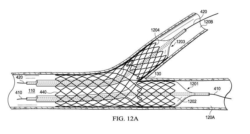
[0030] FIGS. 12A and 12B arc diagrams of three stents being positioned at
the
bifurcation according to some embodiments. Fig 12B demonstrating the final
results of the
creation of a true pantaloons bifurcation stenting configuration.
[0031] FIGS. 13A and 13B are simplified diagrams of an open-cell and a
closed-cell
stent according to some embodiments.
[00321 FIG. 13C is a diagram of a bifurcation stent delivery device
employing a
single-lumen catheter, according to some embodiments. Here the second wire is
trapped
under the stent by crimping the stent over it.
CA 02846634 2014-02-25
WO 2013/033215 PCT/US2012/052864
7
[0033] FIG. 14 is a flowchart of a bifurcation stent delivery device
assembly using a
single-lumen catheter with a closed-cell stent according to some embodiments.
[0034] FIG. 15 is a flowchart of a bifurcation stent delivery device
assembly using a
single-lumen catheter with an open-cell stent according to some embodiments.
[0035] FIGS. 16A-C are diagrams of alternative delivery devices according
to some
embodiments.
[0036] FIGS. I 7A-B illustrate a three-stent delivery device according to
an alternative
embodiment.
100371 While this specification provides several embodiments and
illustrative
drawings, a person of ordinary skill in the art will recognize that the
present specification is
not limited only to the embodiments or drawings described. It should be
understood that the
drawings and detailed description are not intended to limit the specification
to the particular
form disclosed, but, on the contrary, the intention is to cover all
modifications, equivalents
and alternatives falling within the spirit and scope of the claims. Also, any
headings used
herein are for organizational purposes only and are not intended to limit the
scope of the
description. As used herein, the word "may" is meant to convey a permissive
sense (i.e.,
meaning "having the potential to"), rather than a mandatory sense (i.e.,
meaning "must").
Similarly, the words "include," "including," and "includes" mean "including,
but not limited
to."
DETAILED DESCRIPTION
[00381 This specification discloses systems and methods for accurately
deploying
stents within bifurcated vessels. Examples of "bifurcated vessels" include,
but are not limited
to, bifurcated blood vessels (coronary, carotid, iliac, or other blood
vessels), tracheobronchial
trees, venous systems, ureters, etc. Although the embodiments discussed below
occasionally
refer to specific types of vessels (e.g., blood vessels), it should be
understood that these
examples of intravascular stents arc provided for sake of illustration only,
and not by way of
limitation. Moreover, it should be noted that the various embodiments
illustrated in the
figures and discussed below are not necessarily drawn to scale, but are
instead presented with
dimensions intended facilitate their understanding.
CA 02846634 2014-02-25
WO 2013/033215 PCT/US2012/052864
8
100391 In various
embodiments, the methods described herein include deploying a
stent at the main branch of a bifurcated vessel by positioning the stent
accurately at the carina
of the bifurcation while maintaining access to one or more side branches, and
then deploying
one or more additional stents in the side branches of the bifurcation. In
some
implementations, these methods may be performed by employing at least two
distinct types
or groups of stent delivery devices. A first group of devices includes a
balloon catheter
manufactured with two or more lumens or channels configured to accommodate two
or more
separate guide wires (i.e., a dual-lumen catheter as shown in FIGS. 2A-D, or a
triple-lumen
catheter, as shown in FIG. 2E). The pre-manufactured models may include
multiple balloons
in some embodiments. A second group of devices includes alternatives to the
pre-
manufactured dual-lumen catheter. An existing single-lumen balloon catheter
may be
modified so that it is capable of performing the same or similar operations as
the pre-
manufactured models. For example, a secondary guide wire may be placed between
the stent
and a single-lumen balloon catheter in an "off-label" procedure (e.g.. FIG.
13C).
Additionally or alternatively, a dual-balloon configuration with a single
stent crimped over
two balloons may be designed to help position the stent at the carina (e.g.,
FIG. 16A).
Additionally or alternatively, a stent may be crimped over a combination of a
balloon catheter
and a long tube catheter with an approximately 0.014-inch wire lumen or the
like to facilitate
accurate delivery at the carina while maintaining dual side branch access
through the stent
lumen (e.g., FIGS. 16B and 16C). These various devices, as well as their
corresponding
manufacturing and delivery methods, are described in turn below.
Stent Delivery With Multi-Lumen Balloon Catheters
100401 In some
embodiments, stent delivery devices may employ balloon catheters
manufactured with two or more lumens (the first group or type of devices
described above).
For example, in a dual-lumen configuration, a main lumen may be located in the
axial center
of the balloon shaft, and may be configured to house a main guide wire. A
secondary lumen
may be located along the side of the balloon shaft, and may be configured to
house a
secondary guide wire. The exit point for the secondary lumen may be at the
distal end of the
balloon, and may occur where the balloon tapers¨i.e., at or near a "shoulder
region" of the
balloon. This secondary guide wire may maintain access to a side branch of a
bifurcated
vessel during a stent deployment procedure. In some embodiments, three stents
may be
deployed, one in each branch of the bifurcation. The device may maintain a low
profile to
CA 02846634 2014-02-25
WO 2013/033215 PCT/US2012/052864
9
ensure that it fits in the entity being treated (e.g., a coronary vessel or
other type of vessel).
The stent(s) may be chosen, for example, based on the size of the vessel and
the length of the
lesion.
[0041] In various embodiments, the stent may be positioned on the balloon
so that the
stent is at the shoulder of the balloon, just as the balloon tapers. As the
inventor hereof has
discovered, when the balloon is inflated for stent expansion, the portion of
the balloon distal
to the stent should immediately taper and the balloon should not push the
stent back from its
desired location within the vessel directly at the carina. In contrast,
conventional stent
delivery systems typically place the stent in the center or middle of the
balloon, with a ¨0.5 to
1 mm of balloon extending or "overhanging" proximal and distal to the stent.
The distal
portion of the balloon beyond the distal edge of the stent is generally larger
than either side
branch. During stent inflation, the ends of the balloon that arc not covered
by the stent
expand first. Since side branches are generally smaller than the main branch,
when there is a
size mismatch of the distal balloon with respect to the size of the side
branch vessel, the distal
balloon-end expansion in a conventional delivery system invariably displaces
the stent away
from the carina. Again, at least in part because certain of the techniques
described herein
allow accurate positioning of the stent at the carina of the bifurcation,
these techniques
represent a significant improvement over conventional delivery systems.
Conventionally,
because of branch vessel overlap, it is difficult to identify the true
bifurcation. The bifurcation
seen by angiography may not accurately correspond to the true anatomical
bifurcation. This
difficulty is overcome by the technique described herein, because the
anatomical bifurcation
is physically identified. This not only guarantees that the stent is placed
accurately at the
bifurcation, it also saves the patient from being exposed to additional
contrast and radiation.
[0042] A 0.014-inch guide wire or the like may be placed in each lumen or
channel of
the balloon. The assembled device may be placed in the vessel using the main
guide wire.
As the device moves along main guide wire through the vessel, the secondary
guide wire may
be guided into a side branch. The device may be advanced, for example, until
it naturally
stops at the carina of the bifurcation due to the secondary wire positioned
into the side
branch. At this point, the operator may know or sense that the device is
positioned accurately
at the carina. For example, the secondary wire in the second side branch may
be observed to
buckle slightly and a resistance to forward progress of the stent will be felt
physically by the
operator. Additionally or alternatively, radiolucent markers or the like on
the balloon shaft,
CA 02846634 2014-02-25
WO 2013/033215 PCT/US2012/052864
stent, and/or distal tip of the tube or channel under the stent may facilitate
positioning of the
balloon during this procedure. Also, in some cases, the un-inflated stent may
have a distal
marker or may be more visible because it is not inflated and/or because it is
more radiolucent,
as is the case of platinum chromium stents (e.g., IOW or PROMUS stents).
[0043] The balloon catheter may then be inflated and the stent deployed. In
this
manner, access to the side branch and main branch within the lumen of the
stent may be
maintained with the two guide wires. Next, a first kissing balloon technique
may be used to
splay the stent to conform to the bifurcation. The two balloons may be sized
as per the
approximate diameters of each side branch so as to splay the stent
appropriately without
damaging the side branches. Once the kissing balloons have been inflated, the
stent in the
main branch may be splayed across the carina. Thereafter, stents of the
appropriate size may
be deployed in a kissing manner into the side branches of the bifurcations.
These two stents
may be positioned so that the proximal part of the respective stents is
exactly at the carina. A
second kissing balloon technique may be used to further inflate the branch
stents and the
main vessel stent, and further cause opposition of the stents into the intima
of the vessel.
High-pressure inflations may be used.
[00441 For sake of illustration, a typical procedure for kissing stents
deployment may
be conducted as follows. When one of the kissing balloons is inflated to
approximately ¨10-
16 atm, the other balloon may be inflated to approximately ¨4 atm (and vice
versa for the
other stent). Thereafter, both balloons may be brought down to approximately
¨5-8 atm and
deflated at the same time to ensure that the carina is correctly positioned.
It should be
understood, however, that the inflation pressures to be used arc dependent on
the size of the
vessel, the compliance of the inflating balloons, manufacturer
recommendations, etc. In the
dual balloon stent configuration, for example, the two balloon sizes selected
may be small
enough to not damage the main vessel and yet capable of pre-dilating the
distal side branches
to facilitate the kissing stents to follow.
[0045] In various applications, a stent delivery device may be used to
deploy stents
designed to treat stenosis and/or other vessel conditions. Techniques for
deploying these
stents accurately at bifurcated lesions are described below.
[0046] Turning now to FIG. 1, a diagram of a bifurcated vessel is depicted.
Generally, the lengths and diameters of the various elements of bifurcated
vessel 100 may
CA 02846634 2014-02-25
WO 2013/033215 PCT/US2012/052864
11
vary depending upon their location in a patient's body. As illustrated,
bifurcated vessel 100
includes main branch 110, which splits between side branches 120A-B. Carina
130
represents a region of bifurcated vessel 100 where side branches 120A-B are
joined together.
In some cases, carina 130 may also be referred to as a "vertex" or "crotch
point" of bifurcated
vessel 100. Plaque 140 is illustrated along the surfaces or walls of
bifurcated vessel 100 to
represent stenosis or other types of lesions.
100471 FIG. 2A is a diagram of a dual-lumen balloon catheter according to
some
embodiments. In particular, balloon catheter 200A may include proximal tapered
end 210
and distal tapered end 220. Catheter 200A may also include main or primary
guide wire
lumen (or channel) 230 as well as side or secondary guide wire lumen (or
channel) 240.
Main guide wire lumen 230 may include exit 250, and may be configured to
receive a first
guide wire (i.e., a main or primary guide wire ¨ not shown) through main wire
port 201.
Conversely, side guide wire lumen 240 may include end 260, and may be
configured to
receive another guide wire (i.e., a side or secondary guide wire ¨ not shown)
through second
wire port 202. Balloon inflation port 203 may be utilized deliver dilute
contrast or another
suitable fluid to lumen 280 or chamber 281 so as to inflate catheter 200A
during a delivery
procedure. In some cases, lumen 280 or chamber 281 may at least partially
surround main
guide wire lumen 230.
100481 As illustrated in FIG. 2A, exit 250 of main lumen 230 through shaft
portion
251 may be located at or near the center portion (i.e., the axis) of catheter
200A, whereas end
260 of side lumen 240 may be located at or near (e.g., immediately after)
proximal edge 270
of distal shoulder region 220 of catheter 200A. It may also be noted that
catheter 200A tapers
between proximal edge 270 of distal shoulder region 220 (or end 260) and
distal edge 271 of
distal shoulder region 220, which is where the balloon joins shaft 251 in an
approximately
conical tapered fashion. Accordingly, proximal edge 270 of distal shoulder
region 220 may
sometimes be referred to as a "tapered edge," "tapered shoulder," or
"shoulder" of catheter
200A.
100491 In some embodiments, proximal edge 270 may be defined as the point
along
catheter 200A where it begins to taper into region 220. And in some cases, end
260 may be
located exactly at proximal edge 270. In other cases, end 260 may be located
at a distance
from proximal edge 270 so that lumen 240 ends before edge 270 or extends
beyond edge 270.
CA 02846634 2014-02-25
WO 2013/033215 PCT/US2012/052864
12
[0050] The individual guide wires may be placed through the main vessel and
into the
two side branches of the bifurcation before the dual lumen stent balloon is
loaded. In this
case, the guide wires should not be twisted around each other, which would
obstruct the
movement of the stent balloon as it travels along the guide wires and through
the main vessel
to the carina location. In some cases, the dual lumen catheter in the
configuration of FIGS.
2A-2E may aid in such parallel placement of wires. In the configuration of
FIG. 4C, for
example, such parallel placement of the guide wires may be achieved beforehand
(e.g., the
Twin Pass Dual access Catheter model 5200 by Vascular Solutions Inc.).
[0051] FIGS. 2B-E illustrates alternative embodiments of a dual-lumen
balloon
catheter. Particularly, FIG. 2B shows side guide wire lumen 241 with end 261
located at
distal edge 272 of proximal tapered portion 210 of catheter 200B. In some
cases, the
embodiment of FIG. 2B may be used, for example to deliver a stent distal to
the carina of a
bifurcated vessel (as shown in FIGS. 4D and 4E).
100521 FIG. 2C shows side guide wire lumen 242 with first exit 262 located
at or near
distal edge 272 of proximal tapered portion 210 (i.e., a "first tapered edge")
and end 260
located at or near proximal edge 270 of distal tapered portion 220 (i.e., a
"second tapered
edge") of catheter 200C. As such, the embodiment of FIG. 2C is a "universal"
balloon
catheter with the capability to accurately deliver a stent located proximal or
distal to the
carina.
[0053] FIG. 2D shows an alternative configuration of side guide wire lumen
243 with
end 263 located at proximal edge 270 of distal tapered portion 220, but
running alongside
main guide wire lumen 230 for a least a portion of the length of balloon
catheter 200D.
[0054] FIG. 2E shows yet another alternative configuration of a universal
balloon
catheter 200E with two wire lumens; lumen 240 terminating at opening 260 at
edge 270 and
lumen 244 terminating at opening 264 at edge 272.
[0055] Referring to FIG. 3, a cross-sectional view of balloon catheter 200A
of FIG.
2A is depicted. In this embodiment, lumen 230 is usually located approximately
at the center
of catheter 200A, and lumen 240 is located outside the perimeter of catheter
200A. In
alternative embodiments, lumen 240 may also be located along the perimeter but
within
balloon catheter 200A. Again, end 260 of lumen 240 may be located at or near
shoulder
CA 02846634 2014-02-25
WO 2013/033215 PCT/US2012/052864
13
region 270 of catheter 200A, near a point where catheter 200 begins to taper
off (i.e.,
proximal edge 270 of distal shoulder region 220).
[0056] In various embodiments, radius 300 of catheter 200A may be designed
so as to
determine an angle or degree of tapering of distal end 220 and to facilitate
insertion of
catheter 200A in vessels of varying sizes. For example, a small radius 300 may
reduce the
profile of catheter 200A. Conversely, a large radius 300 may allow
bifurcations with large
angles and,/or diameters to be properly treated using catheter 200A. In a
number of
applications, the distal balloon end may taper from the shoulder onwards as
rapidly as
technically feasible. Moreover, in some cases, a set of two or more catheters
200A with
different diameters may be available, and a user or operator may select a
suitable one among
the set based on a location within the patient's body where a stent procedure
will be
performed (e.g., coronary arteries may require low profile, etc.).
100571 It should be noted that, except in FIGS. 6, 7, 16A-C and 17A (where
the stcnt
balloon diagram represents an unexpanded balloon with the stent crimped on
it), all other
balloon diagrams (FIGS. 2A-E, 3, and 4A-G) are shown with the balloon expanded
somewhat, but this is entirely for illustrative purposes. Fig 4H is a self-
expanding stent and
does not require a balloon for deployment. Generally speaking, balloon lumen
281 is
collapsed when the stent is crimped on the balloon (i.e., the balloon is
folded in an
unexpanded state under the crimped stent). FIGS. 4E, 8-11, 12A, and 17B may
represent
expanded versions of the stent-balloon configuration in some situations.
[0058] FIG. 4A is a diagram of bifurcation stent delivery device 400A
according to
some embodiments. As illustrated, device 400A utilizes the balloon catheter
200A depicted
in FIG. 2A. Specifically, stcnt 440 may be positioned on the outer surface of
balloon catheter
200A. In some cases, a distal edge of stent 440 may be aligned with edge 270
of shoulder
region 220 on catheter 200A. Main guide wire 410 may be positioned in a vessel
in a
location desired by the operator or surgeon. Note that in most instances, wire
410 may be
placed in the vessel across the lesion in the main branch 110 (shown in FIG 1)
and further
across the first side branch 120-A (shown in FIG. 1), which is choscn because
it is thc more
difficult lesion to cross. Wire 420 may be placed across the other side branch
120B (shown
in FIG. 1) beforehand or after the stent approaches the carinal bifurcation
point 130 (shown in
FIG. 1).
CA 02846634 2014-02-25
WO 2013/033215 PCT/US2012/052864
14
[0059] Main guide wire 410 is inserted through main lumen 230 of catheter
200A into
end 250 and out of proximal end 201 (shown in FIG. 2). Catheter 200A is then
advanced
along guide wire 410 into the vessel and positioned as desired. Similarly,
side guide wire 420
may be inserted through side lumen 240 of catheter 200A into end 260 and out
end 202 (also
shown in FIG. 2). In other embodiments, as shown in FIGS. 28 and 2C, lumen 240
may
terminate at the distal shoulder 272 of tapered region 210, where side guide
wire 420 may
exit through end 261 or exit 262 (shown in FIGS. 2B and 2C). Alternatively,
the side
guidewire 420 may be introduced through the proximal end 202 into lumen 240 to
exit from
the end 260, 261 or 262 as the case may be, after the catheter 200A has
already been
advanced into the artery close to the carina.
[0060] FIG. 4B shows an alternative configuration for bifurcation stent
delivery
device 400B according to some embodiments. Specifically, device 400B employs
balloon
catheter 200D shown in FIG. 2D.
[0061] FIG. 4C shows stent delivery device 400C where the second side guide
wire
channel 244 is approximately the same length as the cylindrical portion of the
balloon and
slightly longer than the stent 440 spanning from shoulder 272 to shoulder 270.
In this
configuration, both wires 410 and 420 may be placed across the main branch and
side
branches 120A and 120B (shown in FIG. 1) before threading the guide wires into
the stent
delivery device 400C. Wires 410 and 420 may be of approximately the same
lengths
allowing for one catheter to be exchanged for another.
[0062] FIG. 4D illustrates a bifurcation stent delivery device 400D using
balloon
catheter 200B of FIG. 2B. In this embodiment, as previously shown, side guide
wire 420
may leave side guide wire lumen 240 through end 261. As such, this device
configuration
may be particularly well suited for accurately placing stent 440 at the carina
beyond the main
branch and into one of the side branches 120A or 120B (shown in FIG. 1).
[0063] FIG. 4E shows device 400D positioned within side branch 120A beyond
carina 130. As device 400D is insertion into side branch 120A, guide wire 420
causes device
400D to stop at carina 130 with stent 440 accurately located at carina 130 and
extending into
branch 120A. In some cases, such a technique may be used, for example, to
preserve side
branches and/or to prevent jailing of the side branch¨i.e., prevent the stent
from deployed in
such a way as to block or partially block access to the side branch Besides
accurate
CA 02846634 2014-02-25
WO 2013/033215 PCT/US2012/052864
positioning of the stent beyond the carina, the added advantage of this
technique is that the
wire 420 maintains access to the side branch 120B in case side branch 120B
needs
intervention should the carina shift laterally and obstruct blood flow to the
side branch 120B.
100641 FIG. 4F shows bifurcation stent delivery device 400F employing
balloon
catheter 200C of FIG. 2C. Particularly, balloon 200C may have two exit points
(260 and
262) in lumen 242 for guide wire 420. For example, wire 420 may leave catheter
200C
through exit 260 (at or near edge 270 of distal tapered region 220) for
placement of stent 440
at the carina of a bifurcation and just before a side branch. Proximal exit
point 262 (at or near
edge 272 of proximal tapered region 210) may be used to place stent 440
accurately after the
carina and within a side branch.
[0065] FIG. 40 shows device 400G with a balloon catheter with three lumens
¨
center lumen 230 and side lumens 240 and 245. Each lumen is configured to hold
a different
guide wire 410, 420, 430. As such, device 400G may be particularly well suited
for a
procedure involving a trifurcation or the like (e.g., where a vessel includes
a main branch
splitting into three side branches). In this case, each of guide wires 410,
420, 430 may
facilitate positioning a stent with respect to each of three side branches.
100661 FIG. 4H shows bifurcation delivery device 400H in a configuration
suitable
for use with self-expanding stents. Particularly, device 400H includes outer
sheath 450, self-
expanding stent 440, and inner shaft 460, as well as main lumen 230 and side
channel 246.
Delivery of stent 440 may be accomplished by unsheathing stent 440, for
example, by pulling
back outer sheath 450. In the experience of the inventor hereof, the self-
expanding stent
should be oversized to the extent that it has to splay and closely conform to
the spread of the
bifurcation. Often the stent has to be partially released a millimeter or two
before the carina
and simultaneously gently advanced forward to get it to the carina and
sometimes a fraction
of the strut length beyond the carina. Thus, a method of deploying a self-
expanding stent
may be different from another method using a balloon expandable stent.
Typically, self-
expanding stents are intended for peripheral use. A bifurcation deployment may
be
considered, for example, the common Iliac bifurcation to the external and
internal Iliac or the
common femoral to superficial femoral and profound femoris bifurcation. The
use of a
second wire lumen 246, as described herein, may allow accurate placement of
the stent at the
bifurcation while allowing for luminal placement of both of the wires in each
side branch vis-
à-vis the stent in the main vessel.
CA 02846634 2014-02-25
WO 2013/033215 PCT/US2012/052864
16
100671 FIG. 5 is a flowchart of a bifurcation stent delivery technique
according to
some embodiments. To further illustrate this technique, reference is also made
to FIGS. 4A-
G and 6-12. At block 505, a user or operator may position a stent (e.g., stent
440 in FIG. 4A)
with its edge at or near at or near a proximal edge (e.g., 270) of distal
shoulder region (e.g.,
220) of a balloon catheter (e.g., 200A). At block 510, the user may insert a
first guide wire
(e.g., main wire 410) in a first lumen, channel, or cavity (e.g., main lumen
230) of the
catheter and/or may also insert a second guide wire (e.g., side wire 420) in a
second lumen,
channel, or cavity (e.g., side lumen 240) of the catheter. In other cases,
however, a medical
device manufacturer or the like may perform the operations indicated in blocks
505 and 510
to provide a pre-assembled bifurcation stent delivery device as shown in FIGS.
4A-G.
[0068] At block 515, the user may place the bifurcation stent delivery
device in a
patient's vessel using the first guide wire. For example, if the main guide
wire is the "first
guide wire," it may be placed across the mail vessel and into one of the
branches. Typically,
the first guide wire may be placed across the lesion in the main branch and
the side branch
that presents the more challenging stenosis to cross. This operation is shown
in FIG. 6, as
device 400A is introduced into main branch 110 toward the bifurcation into
branches 120A
and 120B. The second guide wire may be placed in the second branch (e.g. 120B)
beforehand or as the stent approaches the bifurcation depending upon the
configuration of the
bifurcation stent delivery device. In some cases, a portion of side wire 420
leaving the device
may be shaped at a first acute angle alpha (a) designed to (at least
approximately) match a
second acute angle beta (13) between side branches 120A and 120B, and
therefore be inserted
into side branch 120B. FIG. 6 also shows main wire 410 positioned inside one
of the
branches (e.g., branch 120A) of bifurcation 100 (for ease of illustration,
stenotic plaques are
not drawn). It will be understood that the main branch 110 and side branches
120A and 120B
as drawn in the figures are merely examples for the purpose of illustration.
The stents and
methods described herein may be used with any sizes and any configuration of
the main
branch 110 and side branches 120A and 120B.
[0069] Returning to block 515, the user may advance device 400A until it
stops at the
carina of the bifurcation. This is illustrated in FIG. 7, where device 400A
positions stent
(e.g., 440) exactly at carina 130. In particular, FIG. 7 shows that side wire
420 may enter the
other side vessels (e.g., 120B), and thus cause the insertion of device 400A
to naturally stop
at carina 130.
CA 02846634 2014-02-25
WO 2013/033215 PCT/US2012/052864
17
[0070] At block 520, the user may inflate the balloon catheter to deploy
the stent
while maintaining access to the first and second branches of the bifurcation
via the first and
second guide wires, respectively. FIG. 8 shows catheter 200A after it has been
inflated so
that expanded stent 440 is correctly positioned with respect to the
bifurcation. FIG. 9 shows
stent 440 expanded at carina 130 and straddling it after the catheter 200A has
been deflated
and removed. FIG. 9 also shows that side guide wire 420 has been positioned
deeper within
side branch 120B after deflation of catheter 200A. This may be achieved by
advancing wire
420 into the side branch 120B simultaneously as the balloon deflates.
Subsequently, the
balloon catheter may be removed in a manner so that both guide wires (410 and
420) remain
in place in each respective side branch. Importantly, it should be noted that
both wires (410
and 420) arc within the lumen of the stmt.
100711 At block 525, the user may apply a first kissing balloon procedure
to splay the
deployed stent 440 and to cause it to more fully conform to the walls of the
bifurcation
between the first and second side branches. FIG. 10 shows balloons 1000 and
1010, which
have been advanced along their respective guide wires 420 and 410 through
expanded stent
440 and into the side branches. The balloons 1000 and 1010 are inflated,
thereby causing
stent 440 to further expand and conform to the shape of the vessel at the
bifurcation. After
inflation of balloons 1000 and 1010, stent 440 is splayed across the
bifurcation at carina 130.
FIG. 11 is a diagram illustrating stent 440 fully splayed across carina 130 as
a result of the
first kissing balloon procedure after the balloons have been deflated and
removed.
[0072] Returning to FIG. 5, at block 530 the user may apply a second
kissing balloon
procedure to deploy a kissing stent within each branch of the bifurcation. The
second kissing
balloon procedure is illustrated in FIGS. 12A and 12B. FIG. 12A shows balloon
1201 with
stent 1202 and balloon 1203 with stent 1204. Balloons 1201 and 1203 have been
advanced
along the guide wires 410 and 420, respectively, through expanded stent 440
and into the side
branches. Balloon 1201 and first kissing stent 1202 arc positioned within
first branch 120A
and then balloon 1201 is inflated to expand stent 1202. Balloon 1203 and
second kissing
stent 1204 are positioned within second branch 120B and then balloon 1203 is
inflated to
expand stent 1204.
[0073] FIG. 12B depicts the result of the second kissing balloon procedure
with the
deploying devices 1201 and 1203 removed from the vessel. As shown in FIGS. 12A
and
12B, there may be an area of overlap between or among stents 440, 1202, and
1204 during
CA 02846634 2014-02-25
WO 2013/033215 PCT/US2012/052864
18
inflation and after the balloons have been withdrawn. Unlike conventional or
traditional
bifurcation stenting methods, the methods described herein may ensure that the
deployed
stents are positioned accurately at the carina and cover the entire
bifurcation uniformly.
Depending upon the type of stent used, this may allow anti-restenosis drugs to
be uniformly
delivered to the bifurcation. Additionally, it is also to be noted that the
methods described
herein may ensure that all stent struts are opposed to the walls of the
bifurcation, thus
minimizing or otherwise reducing the chance of stent thrombosis.
100741 Therefore, using the techniques outlined above, stents 1202 and 1204
may be
positioned at the carina 130. These stents may be the regular pre-mounted
stents, and in most
cases may not need to be reconfigured in any way. The stents used in the
second kissing
procedure may be deployed at the same time or sequentially. The configuration
shown in
FIG. 4E may be used to deploy stents 1202 and 1204 accurately at the carina
130 and beyond.
For example, a first stent delivery device may enter the vessel with lumen 230
on the wire
410 and with side branch wire 420 going through lumen 241. This would be used
to deploy
stent 1202. A second stent delivery device may then enter the vessel with
lumen 230 on wire
420 and with side branch wire 410 going through lumen 241. This would be used
to deploy
stent 1204.
100751 After stents 1202 and 1204 have been deployed, another kissing
balloon
inflation across the bifurcation (e.g. FIG. 10) may be employed to complete
the procedure
and cause optimal or otherwise improved expansion and opposition of the stents
to the wall
of the vessel. This particular stent deployment technique at the carina may
save on the
amount of radiation and/or contrast usage, and it may improve patients'
outcomes due to its
ability to position stents accurately at the carina.
Alternatives to Multi-Lumen Balloon Catheters
[0076] In some situations, a pre-configured or pre-manufactured dual-lumen
balloon
catheter may not be readily available to a user. However, one or more of the
stent
deployment methods described herein may be used with single-lumen,
conventional
catheters. This is the second group or type of devices referred to above. For
example, a dual-
guide wire stent may be constructed from a single-lumen catheter stent by
adding a second
guide wire between the stent and the balloon. The stent may be removed from
the balloon
CA 02846634 2014-02-25
WO 2013/033215 PCT/US2012/052864
19
and the second guide-wire positioned inside the stent. The stent may then be
reinstalled on
the balloon.
[0077] Starting with a single-lumen catheter, a stent delivery device may
be
assembled in different ways depending upon the type of stent being used (i.e.,
a closed-cell
stent versus an open-cell stent). For example, the operation of removing the
stent from its
balloon catheter may be performed differently open-cell versus closed cell
stents, so as to
maintain the integrity of the stent. Typically, open-cell stents cannot be
properly crimped
back onto the balloon once expanded because non-linked struts tend to not fold
back well. In
contrast, a closed-cell can usually be crimped back after being expanded. For
example, if
Medtronic Inc.'s ENDEAVOR'- or RESOLUTE INTEGRITY' open-cell stents are used,
the
stent may be taken off the balloon without inflating the balloon catheter.
Alternatively, a
closed-cell stent such as Cordis Corporation's CYPHER stent may be taken off
the balloon
by first inflating the balloon and then expanding the stent.
100781 The dual balloon and other configurations of open-celled stents as
described
herein may be pre-manufactured. This would ensure that the open cell stents
are not damaged
by manual handling of the stents.
[0079] This stent configuration (i.e., a balloon catheter, a stent, and a
second guide-
wire positioned between the balloon and the stent) may be constructed by the
operator or
may be pre-built by a manufacturer. An advantage of this configuration is that
its cross-
section profile may be the lowest, especially if the device is pre-built by
the manufacturer,
due to the missing side lumen. However, the same configuration may require
above-
average operator skill to maneuver the second wire trapped under the stent
into the side
branch. Specifically, the entire balloon-stent-second-wirc device may have to
be
maneuvered into the main branch and turned so that the second wire enters thc
second
side branch. In some cases, to alleviate these concerns, a spring-coiled tip
wire (e.g.,
Boston Scientific Corp.'s CHOICE Floppy Guide Wire or the Zinger Support
Guidewire by Medtronic) may be used as the second wire under the stent and the
tip may
be steered into the second side branch, even though the spring coil is under
the stent,
because the distal wire tip is connected to the steel core of the wire under
the spring coils.
[0080] Again, in the case of the off-label use of a closed-cell stent, for
example, a
traditional stent balloon (e.g., the CYPHER stent) may be inflated outside the
body and the
CA 02846634 2014-02-25
WO 2013/033215 PCT/US2012/052864
stent expanded. A secondary wire (e.g., a 0.014 spring tip wire because the
internal stent
wire is attached to the tip and can rotate the tip even if the wire is under
the crimped stent)
may be introduced between the balloon and the stent struts. The stent may be
re-crimped to
trap the secondary wire between the stent and the balloon. In some
applications, an
approximately ¨3-5 mm tip of the wire may be kept curved beyond the stent.
Additionally, a
0.014 guide wire may be introduced to the main (or only) lumen to prevent
damage to this
channel when re-crimping the stent. As described above, the stent may be
positioned forward
onto the distal shoulder of the balloon, usually at the distal edge of the
distal balloon marker
on the shaft. The stent may be then re-crimped (e.g., manually by the
operator's fingers), and
a #2.0 silk or the like may be wrapped around the stent and further crimped
manually. A 6F
sheath may also be cut into approximately ¨1.5-2.5 inches, split, and placed
on the shaft of
the balloon with the second wire in it. The proximal side of this piece of the
sheath may be
beveled and used to introduce the stent through the valve of a Touhy borst
adapter or another
medical apparatus used for attaching catheters to other devices. The stent may
be loaded on
the wire that is main branch of the bifurcation. As the stent is advanced, the
secondary wire
may be manipulated so that it enters the side branch of the bifurcation.
Again, the stent may
advance until it stops naturally at the carina. After the stent is deployed at
the carina and the
balloon is being deflated, the side branch wire may be advanced into the side
branch, and the
process may continue similarly as otherwise described herein.
100811 In the case of the off-label use of an open-cell stent, an operator
may receive
an assembled device including a balloon catheter and the open-cell stent. As
before, the
balloon catheter may be a single-lumen catheter¨i.e., configured to accept
only one guide
wire. However, rather than inflating the balloon to expand the stent, the
operator may slide
the stent off of the balloon to remove it from the assembly. The stent may be
loosened off the
balloon by rocking the proximal and distal portions of the balloon shaft
within the stent in
multiple directions. This expands the stent minimally to get it off the
balloon. For example,
in some cases an approximately ¨8-9 mm stent may be used for this purpose.
Then, a second
guide wire may be added between an inner surface of the stent and an outer
surface of the
balloon catheter, and the stent may be slid back over the catheter, thus
trapping the second
guide wire between the stent and the catheter. The distal edge of the stent in
the assembled
device may be at the distal shoulder region of thc balloon. The stent may be
re-crimped
manually, for example, with a #2 silk thread similarly as described for the
closed-cell stent
above.
CA 02846634 2014-02-25
WO 2013/033215 PCT/US2012/052864
21
100821 In some situations, when there is a stent with a second wire under
the stent,
either assembled at the time of the case with available materials (as
described above) or pre-
manufactured as described herein, an introducer device may be used to get the
stent-wire
configuration across a hemostasis valve without damaging or changing the shape
of the
second guide wire tip protruding from the distal edge of the stent. Such an
introducer may be
manufactured in vitro, for example, by cutting an appropriate length of a #6
French sheath as
described above.
100831 FIG. 13A illustrates open-cell stent 1305 that may be used to
assemble a
bifurcation delivery device following the operations described in connection
with FIG. 14.
Particularly, open-cell stent 1305 with a crown of struts 1330 may have one or
more struts
unattached to the adjacent crown of struts, thus creating a few struts 1310
that are
interconnected. In this case, cells 1340 arc considered to be open¨although,
typically, one
of every 3-6 cells may be connected to each other.
100841 FIG. 13B shows closed-cell stent 1315, which may be used following
the
operations described in FIG. 15. In contrast with open-cell stent 1305, every
crown of struts
1335 of closed-cell stent 1315 is connected to the adjacent crown of struts
1335, thus creating
all closed cells 1320.
100851 FIGURE 13C shows an example of a bifurcation stent delivery device
employing a single-lumen catheter, as described above. Device 1300 is similar
to device
400C shown in FIG. 4C, but without second lumen 244. In device 1300, side
guide wire
1301 is crimped between stent 1302 and catheter 1303. Although stent 1302 is
illustrated as
a closed-cell stent (e.g., as in FIG. 13B), an open-cell stent may also be
used (e.g., as in FIG.
13A). In situations where the device is assembled by an operator in an "off-
label" procedure
(i.e., as opposed to pre-built by a manufacturer), the methods depicted in
FIGS. 14 and 15
may be employed. Main guide wire 1304 is positioned in the vessel across the
bifurcation
and into a first branch. Device 1300 may be advanced along main guide wire
1304 into the
vessel toward the bifurcation. Side guide wire section 1301A will be guided
into the second
branch as device 1300 approaches the bifurcation. Wire section 1301A may be
curved to
assist in "catching" the second branch. This will stop the balloon 1303 and
stent 1302
adjacent to the carina of the bifurcation. The stent may then be deployed and
splayed across
the bifurcation as described above.
CA 02846634 2014-02-25
WO 2013/033215 PCT/US2012/052864
22
[0086] Turning now to FIG. 14, a flowchart of a bifurcation stent delivery
device
assembly using a single-lumen catheter with a closed-cell stent (e.g., in FIG.
13B) is depicted
according to some embodiments. At block 1405, the user may inflate the balloon
to expand
the stent outside the patient's body. At block 1410, a user may position a
stent at a forward
shoulder of a balloon catheter having a single lumen. Positioning the stent at
the forward
shoulder of the lumen will help to deploy the stent right at the carina of the
bifurcation. At
block 1415, the user may insert a secondary wire between the balloon and the
stent. Then, at
block 1420, the user may re-crimp the stent to trap the secondary wire between
the stent and
the balloon while leaving a curved portion beyond the stent. The curved
portion will be
directed into a side branch at the bifurcation to help position the stent at
the carina.
[0087] The technique shown in FIG. 14 is particularly suitable for use with
closed-
cell stents, where the stent is amenable to bcing expanded and re-crimped,
thus returning to
its original configuration. As the inventor hereof has recognized, in the case
of open-cell
stents, it may not be possible to return the stent to its original form after
its initial expansion.
Nonetheless, it has been determined that, with respect to pre-assembled stent
delivery devices
having an open-cell stent surrounding a balloon catheter, the open-cell stent
in certain types
of stents, may be removed from the assembly without causing damage to the
stent or to the
catheter without inflating the stent.
[0088] Accordingly, FIG. 15 is a flowchart of a bifurcation stent delivery
device
assembly using a single-lumen catheter with an open-cell stent according to
some
embodiments. At block 1505, the user or operator may receive the pre-assembled
delivery
device and may slide the open-cell stent off of the catheter to remove it from
the assembly.
In some cases, this operation may require that the user apply some amount of
manipulation to
loosen the stent and use some amount of gentle force to get the stent off the
balloon. At
block 1510, the operator may insert a secondary guide wire between the balloon
and the stent.
Then, at block 1515, the user may slide the stent back over the balloon
catheter, thus trapping
the secondary guidc wire between the stcnt and the balloon while positioning
the distal edge
of the stent at the tapered edge of the balloon, typically farther forward
that its original
position in the assembly.
[0089] In some cases, the pre-assembled device may be such that the edge of
the
open-cell stent is positioned at the distal shoulder region of the catheter
(e.g., very close to, or
exactly on the tapered edge). In many applications, such repositioning of the
open-cell stent
CA 02846634 2014-02-25
WO 2013/033215 PCT/US2012/052864
23
may ensure that the second guide wire, now trapped between the stent and the
balloon
catheter, will cause a) the stent to stop at the carina of the bifurcation and
b) the stent to be
deployed accurately at the carina of a bifurcation during balloon expansion.
100901 FIGS. 16A-C are diagrams of alternative delivery devices according
to some
embodiments. Particularly, FIG. 16A shows a dual balloon configuration 1600
with single
stent 1601 crimped over two balloons 1602 and 1603. Radiopaque markers on the
shaft or
the stent may be used to help position the stent at the carina. In some
implementations, a
commercially available stent-balloon catheter may be modified by crimping
stent 1601 over
two parallel balloon catheters 1602 and 1603. Balloons 1602 and 1603 are sized
to fit into
the first and second side branches of a bifurcation. Two parallel guide wires
1605 and 1606
are first placed in the vessel and each guide wire is positioned into its own
side branch of the
bifurcation. Each balloon 1602, 1603 is then advanced along the guide wires
1605 and 1606
though the vessel to the bifurcation. The two balloon-stent device 1600 may
stop at the
carina and the stent then may be deployed at this location by inflating both
the balloons at the
same time. In such an embodiment, the deployment and splaying of the distal
portion of the
stent may occur at the same time as pre-dilatation of the stenosis in the
first and second side
branches. If only open-cell stents are available on the market, this dual
balloon configuration
may be pre-manufactured. The configuration may be used with the closed-cell
Cypher stent,
but this stent is currently off the market and no longer available from the
manufacturer.
[0091] FIG. 16B depicts stent delivery device 1610 according to an
alternative
embodiment. Specifically, stent 1611 is crimped over a parallel combination of
balloon
catheter 1612 (for a first guide wire) and a long tube catheter 1613 with an
approximately
0.014-inch wire lumen (for a second guide wire). Device 1610 may also include
markers (not
shown) on the shaft of the stent itself to assist in positioning the device.
The embodiment of
device 1610 with catheter 1613 may facilitate accurate delivery at the carina
while
maintaining dual side branch access through the stent lumen.
100921 FIG. 16C depicts another embodiment of a stent delivery device.
Stent 1621
is crimped over balloon catheters 1622 and 1623. The catheters have inflation
balloon
sections that are longer than stent 1621. As a result, sections 1625 on each
balloon 1622,
1623 extend beyond the distal edge of stent 1621. This configuration may be
useful, for
example, to dilate each side branch 120A and 120B (FIG. 10) of the bifurcation
when stent
1621 is deployed. This would prepare the side branches for a subsequent
kissing stenting
CA 02846634 2014-02-25
WO 2013/033215 PCT/US2012/052864
24
operation. Additionally, the inflation of segments 1625 in different side
branches would
cause stent 1621 to be splayed across the bifurcation with the first inflation
itself. This
embodiment may make it easier to splay stent 1621 in order to achieve the
configuration
depicted in of FIG. 10 and FIG. 11, for example.
[0093] FIG. 17A illustrates a three-stent delivery device 1700 according to
another
alternative embodiment. A stent 1704 is positioned on balloon 1702 and stent
1705 is
positioned on balloon 1703. Thereafter stent 1701 is positioned around both
the balloon
catheters 1702 and 1703, with the distal end of the stent overlapping the
stents 1704 and
1705. This configuration allows for the simultaneous deployment of stent 1701
in the main
vessel before a bifurcation and deployment of stents 1704 and 1705 in separate
side branches.
[0094] FIG. 17B illustrates device 1700 deployed at a bifurcation. First,
guide wires
1706, 1707 are positioned though main vessel 110 and into separate side
branches 120A,
120B. Then, device 1700 is advanced along the guide wires with balloon
catheter 1702
traveling along guide wire 1706 and balloon catheter 1703 traveling along
guide wire 1707.
As device 1700 approaches the bifurcation, the balloons are directed into
separate side
branches. The device will stop moving into the vessel when the balloon
segments covered by
stents 1704 and 1705 have entered the side branches. Stent 1701 cannot move
into the side
branches, but will be stopped at carina 130. Once the device 1700 is
positioned with stent
1701 at the carina in this manner, the balloons 1702, 1703 may be inflated as
illustrated in
FIG. 17B. This inflation will simultaneously deploy stent 1701 in the main
vessel proximal
to carina 130 and stents 1704, 1705 in the side branches distal to carina 130.
Additionally,
device 1700 performs the kissing balloon techniques when it is inflated, which
splays stent
1701 across the bifurcation.
[0095] As a person of ordinary skill in the art will recognize in light of
this disclosure,
one or more of the numerous embodiments described herein may provide one or
more
advantages over known stent deployment techniques. For example, some of these
embodiments may prevent guide wires from becoming tangled. In some cases,
access to a
side branch may be maintained using the second guide wire when deploying a
stent in the
main vessel. Furthermore, the wire going into the side branches may be
maintained within
the lumen of the stent, rather than through the stent struts. One or more of
the techniques
disclosed herein may also guarantee the exact location of the stent at the
carina, which makes
CA 02846634 2014-02-25
WO 2013/033215 PCT/US2012/052864
it less likely that areas of the bifurcation lesion will remain uncovered by
stents after
treatment.
[0096] Moreover, in contrast with existing devices currently used to treat
bifurcation
lesions, one or more of the devices disclosed herein may be manufactured with
a low or small
profile, may be easy to maneuver, and may therefore be particularly well
suited for the
treatment of coronary arteries, which are typically small in diameter
(although it may also be
used in any bifurcation lesion). In some devices, the side lumen may ensure
access to the
side branch of the bifurcation. Further, in some cases, the side guide wire
may help place the
main stent exactly at the carina. Because in embodiments where the bare wire
is trapped
under the stent the side guide wire is generally unable to move within the
lumen, a 'V' shape
may be created between the guide wire and the balloon catheter of the main
branch stent. As
the device advances with the side wire in the side branch and the main wire in
the main
branch, it may stop at the vertex of bifurcation. As such, one or more of the
techniques
described herein may guarantee precise placement of a stent at the carina with
any amount of
plaque buildup in the arteries, and while ensuring there is full coverage of
the bifurcation.
Under fluoroscopy in two dimensions, it is often very difficult to identify
the precise location
of the carina in two dimensions because of variable side branch vessel
overlap. Hence the
particular suitability of certain of these techniques and innovations to
accurately place stents
at bifurcations in coronary, peripheral vascular, venous or other anatomical
locations.
[0097] In some cases, the stent delivery systems and methods described
herein may
provide a 100% or near 100% apposition or coverage of the bifurcation lesion
by the stent
struts, thereby eliminating a limitation of present day stenting of such
lesions. In a typical
scenario, 100% coverage of the lesion may be a particularly critical issue
with local lesion
drug delivery by drug eluting stents to prevent restenosis. In addition, 100%
or near 100%
stent apposition to the bifurcation lesion ensures that luminal access to each
branch is wide
open¨that is, stent struts do not protrude into the lumen and a true
pantaloons configuration
may be obtained. This method of stenting may therefore eliminate or otherwise
reduce the
risk of stent thrombosis due to stent struts that are not opposed to the wall
of the vessel.
Furthermore, in the case of restenosis or new lesions developing downstream to
the
bifurcation, normal anatomical access allows subsequent operators to cross
through the
bifurcation with wires, balloons and stents without any metallic lumina(
obstacles caused by
struts not in apposition to the walls of the bifurcation.
CA 02846634 2014-02-25
WO 2013/033215 PCT/US2012/052864
26
[0098] In some cases, the stent delivery systems and methods described
herein may
also prevent the carina of the bifurcation from being shifted from its
anatomical location.
This may be guaranteed by deflating the kissing balloons together at the same
inflation
pressures. The stent in the main vessel may be accurately delivered at the
carina by making
sure that the distal end of the stent is positioned forward on the shoulder or
distal taper of the
deploying balloon than is the case with more conventional stents. In addition,
problems of
plaque shifting are also eliminated or otherwise reduced. In various
implementations, the
two wires in each lumen may always be within the lumen of the stents and do
not at any time
go through stent struts.
[0099] Certain conventional balloon and stent profiles are small enough to
utilize
certain of the stent delivery techniques described herein, for instance,
through an 8F (crossing
profile of the guiding catheter) system. For example, the closed-cell design
of the CYPHER
stent is particularly suitable for this method because it can be re-crimped
after expanding it
outside the patient's body. Other open cell stents such as, for example, the
ENDEAVOle, or
the RESOLUTE INTEGRITY ' may be loosened and removed from the balloon without
expanding the stent. Also conventional stents, wires, and materials may be
used to
reconfigure a stent for delivery at the bifurcation (i.e., off-FDA label
utilization of these
stents). While such an off-label technique may require a higher level of
operator expertise for
reconfiguration of the stent for the bifurcation, after the initial learning
curve is overcome,
such a method is also very feasible.
[0100] With one or more of the innovations described herein, stent delivery
systems can
be created to make the delivery operator friendly and achieve routine use for
bifurcation
stenting. Additional innovations described herein may be used to accurately
deliver a stent at
a trifurcation, for example, a left-main trifurcation into the left anterior
descending, ramus
intermedius and circumflex arteries. Yet additional innovations may accurately
deliver stents
beyond the carina without jailing a side branch. This may be utilized in other
non-bifurcation
lesion situations where stenting is required in the main vessel but the stent
needs to be
delivered without jailing a side branch, while maintaining access to the
branch in case the
carina is shifted.
[0101] As such, in various embodiments, the stent delivery systems and
methods
described herein may be particularly useful for use with patients who cannot
undergo bypass
surgery safely. Moreover, one or more of these techniques may be safely used
in patients
CA 02846634 2014-02-25
WO 2013/033215
PCT/US2012/052864
27
with "complex" bifurcation lesions, thus making complex bifurcation operations
a matter of
routine; thus helping decrease the need for such surgery.
[0102] The various
systems and methods illustrated in the figures and described herein
represent example embodiments of systems and methods for deploying stents
within
bifurcated blood vessels. The order in which each operation of a given method
is performed
may be changed, and various elements of the systems or devices illustrated
herein may be
added, reordered, combined, omitted, modified, etc. Various modifications and
changes may
be made as would be clear to a person of ordinary skill in the art having the
benefit of this
specification. It is intended that the invention(s) described herein embrace
all such
modifications and changes and, accordingly, the above description should be
regarded in an
illustrative rather than a restrictive sense.