Note: Descriptions are shown in the official language in which they were submitted.
CA 02846709 2014-03-14
"
PROTECTIVE FINISH FOR WING TiP DEVICES
FIELD
The present disclosure relates to wing tip devices. In particular, it relates
to a
protective finish for wing tip devices.
BACKGROUND
Airfoil leading edges and nose cones of aircraft are susceptible to erosion
caused by
debris and/or weathering. As such, currently in industry, protective film or
erosion
caps are used to protect leading edges of airfoils and nose cones from
erosion. For
example, a known polyurethane protective tape has been used on airfoil leading
edges to protect them from erosion. However, this is a flat tape and it does
not have
a contoured shape specific to the airfoil. At least one known aircraft
includes
winglets having a protective film covering on the leading edge of the winglet.
Known
erosion caps include contoured metal sheets mechanically fastened to the
airfoil
leading edge. These erosion caps extend rearwardly covering about ten (10)
percent (/o) of the chord length. As such, the mechanical fasteners and the
back
edge of the erosion cap disturbs the laminar flow. Such protective coverings
and
erosion caps are manufactured to only extended rearwardly covering about 10%
of
the chord length to save on weight and cost.
In addition, laminar flow across a winglet or other airfoil is also disturbed
by steps
that are formed from the layers of paint on the winglet (e.g., painting on the
winglet is
done by applying multiple single-color paint layers, and steps are formed
between
the successive layers of paint). The disruption of laminar flow by the back
edge of
the protective covering or erosion cap and/or by the paint steps increases the
drag
across the airfoil and reduces fuel efficiency.
Therefore, an improved protective finish for wing tip devices is needed.
1
CA 02846709 2016-07-12
..
SUMMARY
In one aspect, the present disclosure relates to a method for a protective
finish for an
airfoil, the method comprising: applying a sheath to a surface of the airfoil
by
wrapping the sheath around the surface of the airfoil from a leading edge of
the
airfoil towards a trailing edge of the airfoil, wherein the sheath covers 50
percent to
70 percent of a chord length of the airfoil, and wherein a back edge of the
sheath is
positioned downstream from a point where airflow over the airfoil in a
direction from
the leading edge towards the trailing edge separates to prevent disruption of
laminar
airflow over the airfoil.
In one or more embodiments, the sheath is manufactured from at least one
polymer.
In at least one embodiment, at least one polymer is a polyurethane and/or a
floropolymer. In some embodiments, the sheath is manufactured from a
polyurethane protective tape manufactured by the 3MTm Company.
In at least one embodiment, the airfoil is a winglet, a raked wing tip, and/or
a wing.
In one or more embodiments, the airfoil is manufactured to have a monocoque
carbon fiber architecture.
In one or more embodiments, the method further involves printing an image on
at
least one side of the sheath. In at least one embodiment, the image is a
customer
livery, such as an airline trademark.
In at least one embodiment, the applying of the sheath to the surface of the
airfoil is
achieved by an adhesion of an adhesive surface of the sheath to the surface of
the
airfoil. In some embodiments, the sheath is manufactured to be contoured
corresponding to a shape of the airfoil.
2
CA 02846709 2016-07-12
In another aspect, the present disclosure relates to a system for a protective
finish
for an airfoil, the system comprising: the airfoil; and a sheath applied to a
surface of
the airfoil, wherein the sheath wraps around the surface of the airfoil from a
leading
edge of the airfoil towards a trailing edge of the airfoil, wherein the sheath
covers 50
percent to 70 percent of a chord length of the airfoil, and wherein a back
edge of the
sheath is positioned downstream from a point where airflow over the airfoil in
a
direction from the leading edge towards the trailing edge separates to prevent
disruption of laminar airflow over the airfoil.
In at least one embodiment, an image is printed on at least one side of the
sheath.
In some embodiments, the sheath is applied to the surface of the airfoil by
adhesion
of an adhesive surface of the sheath to the surface of the airfoil.
In yet another aspect, the present disclosure relates to a wing or wing tip
device
comprising: a body having a leading edge, a trailing edge and a chord length
defined
therebetween; and a sheath wrapped around a surface of the body from the
leading
edge of the body towards the trailing edge of the body and contoured to
correspond
to a shape of the body, wherein the sheath covers 50 percent to 70 percent of
the
chord length of the body, and wherein a back edge of the sheath is positioned
downstream from a point where airflow over the airfoil in a direction from the
leading
edge towards the trailing edge separates to prevent disruption of laminar
airflow over
the airfoil.
The features, functions, and advantages can be achieved independently in
various
aspects and embodiments of the present inventions or may be combined in yet
other
aspects and embodiments.
3
CA 02846709 2016-07-12
DRAWINGS
These and other features, aspects, and advantages of the present disclosure
will
become better understood with regard to the following description and
accompanying drawings where:
FIG. 1 is an illustration of an exemplary current, conventional design for
airfoil
protection.
FIG. 2 is an illustration of the disclosed system for a protective finish for
an airfoil, in
accordance with at least one embodiment of the present disclosure.
FIG. 3 is a cross-sectional view of the lower winglet of FIG. 2, in accordance
with at
least one embodiment of the present disclosure.
DESCRIPTION
The methods and apparatus disclosed herein provide an operative system for a
protective finish for wing tip devices. Specifically, the system employs an
airfoil
sheath that wraps around the leading edge of an airfoil, and extends
rearwardly from
the leading edge towards the trailing edge to cover approximately fifty (50)
to
3a
CA 02846709 2014-03-14
approximately seventy (70) percent (%) of the chord length of the airfoil. As
such,
the back edge of the sheath is positioned downstream from where the flow over
the
airfoil separates. In contrast, as previously mentioned above in the
background
section, current conventional leading edge protection extends only about ten
(10) Yo
of the chord length of the airfoil such that the back edge of the leading edge
protection causes a disruption to the laminar flow across the airfoil.
The current existing design solutions for leading edge erosion protection and
protection of customer livery (e.g., the airline trademark) of wing tip
devices consists
of a discrete metallic sheet attached to the leading edge of the wing tip
device,
where the customer livery is directly painted onto the torque box and trailing
edge
structure. This architecture results in a structural configuration that is
higher in part
count (i.e., it requires multiple detailed parts and mechanical fasteners),
higher in
assembly time (i.e., due to the high part count), and higher in the amount of
tooling
required to complete the assembly. The most significant drawback to these
design
solutions is the limitation of natural laminar flow across the wing tip device
that
occurs due to the joints in the assembled parts and the paint steps used for
the
customer livery.
The disclosed system provides a means to protect the leading edge of wing tip
devices while increasing the natural laminar flow of the wing tip airfoil due
to the
elimination of a discrete attached erosion cap and corresponding streamwise
join in
the wing structure. The disclosed system will provide a protective finish
system that
will protect the leading edge of wing tip devices (e.g., winglets and/or raked
wing
tips), which in some embodiments are of a monocoque carbon fiber architecture.
In
addition, the disclosed system will eliminate the multiple paint steps (i.e.,
one paint
step for each color) that are currently required as a result of a multi-
colored unique
livery, thereby providing a smooth surface to enable natural laminar flow
across the
planform livery.
In particular, the system of the present disclosure utilizes polyurethane
tape(s) (i.e.,
a boot made of at least one thin sheet of polyurethane tape) for erosion
protection
and protection of customer livery on wingtip devices. The customer livery is
digitally
printed on an adhesive backed floropolymer film that covers the inboard and/or
4
CA 02846709 2014-03-14
outboard planform surface of the wing tip device. The printed livery is
wrapped by a
polymer fitted boot that spans from the upper trailing edge to the lower
trailing edge
of the wing tip device. This protective finish system will protect the leading
edge of,
for example, a carbon monocoque airfoil from leading edge erosion as well as
enable greater natural laminar flow due to the elimination of span-wise
splices in the
airfoil.
As previously mentioned, the disclosed system provides a protective coating
that
increase laminar flow across an airfoil, such as a winglet, and provides
erosion
protection for the leading edge. More specifically, the proposed airfoil
sheath
includes a contoured film corresponding to the shape of the leading edges of a
multi-
surfaced winglet. The film has a smooth finish to facilitate laminar flow over
the
leading edges. Further, the sheath extends rearwardly from the leading edge
toward
the trailing edge to cover approximately 50 to approximately 70 % (in some
embodiments, to cover approximately 2/3 is preferable) of the chord length of
the
winglet airfoil. Although the sheath includes more material (i.e., thereby
leading to
added weight and cost) as compared to known film coverings and erosion caps,
the
back edge of the proposed sheath is positioned downstream from the point where
the flow over the winglet separates. As such, the sheath does not disturb the
laminar flow over the winglet. Additionally, the proposed sheath covers the
paint on
the airfoil to shield the paint from contact with the flow over the winglet.
As such, the
steps in the winglet livery paint do not impact the flow over the winglet. The
sheath
can be formed from polyurethane, floropolymer, or other suitable polymer.
In the following description, numerous details are set forth in order to
provide a more
thorough description of the system. It will be apparent, however, to one
skilled in the
art, that the disclosed system may be practiced without these specific
details. In the
other instances, well known features have not been described in detail so as
not to
unnecessarily obscure the system.
FIG. 1 is an illustration of an exemplary current, conventional design 100 for
airfoil
protection.
In this figure, a winglet 110 on a main wing 120 of an aircraft (not
shown) is depicted. The winglet 110 may be manufactured from various different
materials including, but not limited to, carbon fiber and/or aluminum (Al).
The winglet
5
CA 02846709 2014-03-14
110 has a leading edge 130 and a trailing edge 140. In addition, the winglet
110 is
shown to have three segments: a first segment 150, a second segment 160, and a
third segment 170. Also, the customer livery 180 (e.g., the airline
trademark) is
printed directly onto the surface of the winglet 110.
As is shown in this figure, the leading edge 130 of the winglet 110 is covered
with a
thin strip of metal 195 that is riveted to the winglet 110. This thin strip of
metal 195 is
used for protection for the winglet 110 from erosion caused by debris and/or
weathering. For this design, the strip of metal 195 only covers approximately
ten
percent (10%) of the chord length 190 of the winglet 110 and, as such, causes
a
disruption to the laminar flow across the winglet 110.
Also, it should be noted that since the customer livery 180 is printed
directly onto the
surface of the winglet 110, the multiple layers of paint, which are needed to
paint the
different colors of the customer livery 180 (e.g., one layer of paint is
needed for each
color), also cause a disruption to the laminar flow across the winglet 110. In
addition, it should be noted that since the rivets, which are used to attach
the thin
strip of metal 195 to the winglet 110, are not completely flush with the
surface of the
winglet 110, the rivets also contribute to the disruption of the laminar flow
across the
winglet 110.
FIG. 2 is an illustration of the disclosed system 200 for a protective finish
for an
airfoil, in accordance with at least one embodiment of the present disclosure.
In this
figure, a main wing 210 of an aircraft (not shown) is shown to have two
winglets, an
upper winglet 220 and a lower winglet 230. In order to understand the
orientation of
the aircraft (not shown) in this figure, arrow 240 is pointing towards the
location of
the nose of the aircraft, and arrow 250 is pointing towards the location of
the tail of
the aircraft.
For this figure, the disclosed system 200 is illustrated to be employed by the
lower
winglet 230; although it should be understood that the system 200 can be used
with
any suitable airfoil, such as a wiglet, a raked wing tip, and/or a wing.
However, it
should be noted that in various embodiments, both winglets 220, 230 or only
one
winglet 220, 230 (especially for the case of a main wing that only employs one
winglet) may employ this disclosed system 200.
6
CA 02846709 2014-03-14
The lower winglet 230, which employs the disclosed system 200, is shown to
have a
leading edge 260 and a trailing edge 270. The lower winglet 230 also has a
front
spar 280, a mid spar 285, and a rear spar 290. For the disclosed system 200, a
sheath 295 is applied to the surface of the lower winglet 230. The sheath 295
is
applied such that the sheath 295 wraps around the surface of the lower winglet
230
from the leading edge 260 of the lower winglet 230 towards the trailing edge
270 of
the lower winglet 230, and such that the sheath 295 covers approximately 50 to
approximately 70 percent of the chord length 297 of the lower winglet 230.
Preferably the sheath 295 covers approximately two-thirds (2/3) of the chord
length
297 of the lower winglet 230.
The sheath 295 may be manufactured from at least one polymer, such as a
polyurethane and/or a floropolymer.
In some embodiments, a polyurethane
protective tape (e.g., at least one large sheet of tape) manufactured by the
3MTNA
Company is employed for the sheath 295.
In addition, the sheath 295 is
manufactured such that it is contoured corresponding to the shape of the lower
winglet 230.
In one or more embodiments, one side of the sheath 295 is manufactured to have
an
adhesive. For these embodiments, the adhesive side of the sheath 295 is placed
in
contact with the surface of the lower winglet 230 such that the sheath 295
adheres to
the surface of lower winglet 230.
In some embodiments, the sheath 295 is significantly transparent. For these
embodiments, the customer livery may be printed on the side of the sheath 295
that
is in contact with the surface of the lower winglet 230 such that the customer
livery
shows through on the opposite side of the sheath 295. Since the customer
livery is
printed on the underside of the sheath 295 and not the external side of the
sheath
295, the layers of paint of the customer livery are covered by the sheath 295
and,
thus, the paint layers will not cause a disruption to the laminar flow across
the lower
winglet 230.
It should be noted that in other embodiments, the customer livery may be
painted
directly onto the surface of the lower winglet 230, and then the sheath 295
may be
placed on top of the surface of the lower winglet 230, thereby allowing the
paint of
7
CA 02846709 2015-09-25
the customer livery to show through the significantly transparent sheath 295.
Since
the customer livery is printed on the lower winglet 230, which is covered by
the
sheath 295, the layers of paint of the customer livery are covered by the
sheath 295
and, thus, the paint layers will not cause a disruption to the laminar flow
across the
lower winglet 230.
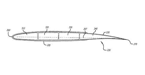
FIG. 3 is a cross-sectional view of the lower winglet 230 of FIG. 2, in
accordance
with at least one embodiment of the present disclosure. In this figure, the
lower
winglet 230 is shown to have a leading edge 260 and a trailing edge 270. The
chord
297 of the lower winglet 230 stretches from the leading edge 260 to the
trailing edge
270. In addition, the lower winglet is shown to contain four cells: a first
cell 310, a
second cell 320, a third cell 330, and a fourth cell 340.
In this figure, the sheath 295 is shown to be applied to the surface of the
lower
winglet 230 such that the sheath 295 wraps around the surface of the lower
winglet
230 from the leading edge 260 of the lower winglet 230 towards the trailing
edge 270
of the lower winglet 230, and such that the sheath 295 covers approximately 50
to
approximately 70 percent of the chord length 297 of the lower winglet 230.
Although certain illustrative embodiments and methods have been disclosed
herein,
it can be apparent from the foregoing disclosure to those skilled in the art
that
variations and modifications of such embodiments and methods can be made
without departing from the scope of the disclosure. The scope of the claims
should
not be limited by the embodiments set forth above, but should be given the
broadest
interpretation consistent with the description as a whole.
8