Note: Descriptions are shown in the official language in which they were submitted.
CA 02846749 2014-03-14
ROTATING CONTINUOUS FLOW SUB
BACKGROUND OF THE INVENTION
Field of the Invention
[0om] The present invention relates to a rotating continuous flow sub.
Description of the Related Art
[0002] In many drilling operations in drilling in the earth to recover
hydrocarbons, a
drill string made by assembling pieces or joints of drill tubulars or pipe
with threaded
connections and having a drill bit at the bottom is rotated to move the drill
bit. Typically
drilling fluid, such as oil or water based mud, is circulated to and through
the drill bit to
lubricate and cool the bit and to facilitate the removal of cuttings from the
wellbore that is
being formed. The drilling fluid and cuttings returns to the surface via an
annulus formed
between the drill string and the wellbore. At the surface, the cuttings are
removed from
the drilling fluid and the drilling fluid is recycled.
[0003] As the drill bit penetrates into the earth and the wellbore is
lengthened, more
joints of drill pipe are added to the drill string. This involves stopping the
drilling while the
tubulars are added. The process is reversed when the drill string is removed
or tripped,
e.g. to replace the drilling bit or to perform other wellbore operations.
Interruption of
drilling may mean that the circulation of the mud stops and has to be re-
started when
drilling resumes. This can be time consuming, can cause deleterious effects on
the walls
of the wellbore being drilled, and can lead to formation damage and problems
in
maintaining an open wellbore. Also, a particular mud weight may be chosen to
provide a
static head relating to the ambient pressure at the top of a drill string when
it is open
while tubulars are being added or removed. The weighting of the mud can be
very
expensive.
[0004] To convey drilled cuttings away from a drill bit and up and out of a
wellbore
being drilled, the cuttings are maintained in suspension in the drilling
fluid. If the flow of
fluid with cuttings suspended in it ceases, the cuttings tend to fall within
the fluid. This is
inhibited by using relatively viscous drilling fluid; but thicker fluids
require more power to
1
CA 02846749 2014-03-14
pump. Further, restarting fluid circulation following a cessation of
circulation may result in
the overpressuring of a formation in which the wellbore is being formed.
[0005] Figure 1 is a prior art diagrammatic view of a portion of a
continuous flow
system. Figure 1A is a sectional elevation of a portion of the union used to
connect two
sections of drill pipe, showing a short nipple to which is secured a valve
assembly.
Figure 1B is a sectional view taken along the line 1B-1B of Figure 1A.
[00os] A derrick 1 supports long sections of drill pipe 8 to be lowered
and raised
through a tackle having a lower block 2 supporting a swivel hook 3. The upper
section of
the drill string includes a tube or Kelly 4, square or hexagonal in cross
section. The Kelly
4 is adapted to be lowered through a square or hexagonal hole in a rotary
table 5 so,
when the rotary table is rotated, the Kelly will be rotated. To the upper end
of the Kelly 4
is secured a connection 6 by a swivel joint 7. The drill pipe 8 is connected
to the Kelly 4
by an assembly which includes a short nipple 10 which is secured to the upper
end of the
drill pipe 8, a valve assembly 9, and a short nipple 25 which is directly
connected to the
Kelly 4. A similar short nipple 25 is connected to the lower end of each
section of the drill
pipe.
[0007] Each valve assembly 9 is provided with a valve 12, such as a
flapper, and a
threaded opening 13. The flapper 12 is hinged to rotate around the pivot 14.
The flapper
12 is biased to cover the opening 13 but may pivot to the dotted line position
of Figure 1A
to cover opening 15 which communicates with the drill pipe or Kelly through
short a
nipple 25 into the screw threads 16. The flapper 12 pivots to cover opening 15
in
response to switching of circulation from hose 19 to hose 29. The flapper 12
is provided
with a screw threaded extension 28 which is adapted to project into the
threaded opening
13. A plug member 27 is adapted to be screwed on extension 28 as shown in
Figure 1A,
normally holding the valve 12 in the position covering the side opening in the
valve
assembly. Normally, before drilling commences, lengths of drill pipe are
assembled in the
vicinity of the drill hole to form "stands" of drill pipe. Each stand may
include two or more
joints of pipe, depending upon the height of the derrick, length of the Kelly,
type of
drilling, and the like. The sections of the stand are joined to one another by
a threaded
2
= CA 02846749 2014-03-14
connection, which may include nipples 25 and 10, screwed into each other. At
the top of
each stand, a valve assembly 9 is placed. It will be observed that the valve
body acts as
a connecting medium or union between the Kelly and the drill string.
[0008] Normally, oil well fluid circulation is maintained by pumping
drilling fluid from
the sump 11 through pipe 17 through which the pump 18 takes suction. The pump
18
discharges through a header 39 into valve controlled flexible conduit 19 which
is normally
connected to the member 6 at the top of the Kelly, as shown in Figure 1. The
mud
passes down through the drill pipe assembly out through the openings in the
drill bit 20,
into the wellbore 21 where it flows upwardly through the annulus and is taken
out of the
well casing 22 through a pipe 23 and is discharged into the sump 11. The Kelly
4, during
drilling, is being operated by the rotary table 5. When the drilling has
progressed to such
an extent that is necessary to add a new stand of drill pipe, the tackle is
operated to lift
the drill string so that the last section of the drill pipe and the union
assembly composed
of short nipple 25, valve assembly 9, and short nipple 10 are above the rotary
table. The
drill string is then supported by engaging a slips (not shown).
[0009] The plug 27 is unscrewed from the valve body and a hose 29, which
is
controlled by a suitable valve, is screwed into the screw threaded opening 13.
While this
operation takes place, the circulation is being maintained through hose 19.
When
connection is made, the valve controlling hose 29 is opened and momentarily
mud is
being supplied through both hoses 19 and 29. The valve controlling hose 19 is
then
closed and circulation takes place as before through hose 29. The Kelly is
then
disconnected and a new stand is joined to the top of the valve body, connected
by screw
threads 16. After the additional stand has been connected, the valve
controlling hose 19
is again opened and momentarily mud is being circulated through both hoses 19
and 29.
Then the valve controlling hose 29 is closed, which permits the valve 12 to
again cover
opening 13. The hose 29 is then disconnected and the plug 27 is replaced.
3
CA 02846749 2014-03-14
SUMMARY OF THE INVENTION
[0010] In one embodiment, a method for drilling a wellbore includes
drilling the
wellbore by advancing the tubular string longitudinally into the wellbore;
stopping drilling
by holding the tubular string longitudinally stationary; adding a tubular
joint or stand of
joints to the tubular string while injecting drilling fluid into a side port
of the tubular string,
rotating the tubular string, and holding the tubular string longitudinally
stationary; and
resuming drilling of the wellbore after adding the joint or stand.
[0oil] In another embodiment, a method for drilling a wellbore,
includes a) while
injecting drilling fluid into a top of a tubular string disposed in the
wellbore and having a
drill bit disposed on a bottom thereof and rotating the tubular string:
drilling the wellbore
by advancing the tubular string longitudinally into the wellbore; and stopping
drilling by
holding the tubular string longitudinally stationary; b) injecting drilling
fluid into a side port
of the tubular string while injecting drilling fluid into the top, rotating
the tubular string, and
holding the tubular string longitudinally stationary; c) while injecting
drilling fluid into the
port, rotating the tubular string, and holding the tubular string
longitudinally stationary:
stopping injection of drilling fluid into the top; adding a tubular joint or
stand of joints to
the tubular string; and injecting drilling fluid into the top; and d) stopping
injection of
drilling fluid into the port while injecting drilling fluid into the top,
rotating the tubular
string, and holding the tubular string longitudinally stationary.
[0012] In another embodiment, method for drilling a wellbore, includes
drilling the
wellbore by rotating a tubular string using a top drive and advancing the
tubular string
longitudinally into the wellbore; rotationally unlocking an upper portion of
the tubular
string having a side port from a rest of the tubular string; adding a tubular
joint or stand of
joints to the upper portion while injecting drilling fluid into the side port
and rotating the
rest of the tubular string using a rotary table; rotationally locking the
upper portion to the
rest of the tubular string after adding the joint or stand; and resuming
drilling of the
wellbore after rotationally locking the upper portion.
[0013] In another embodiment, a continuous flow sub (CFS) for use with
a drill string,
includes a tubular housing having a central longitudinal bore therethrough and
a port
4
CA 02846749 2014-03-14
formed through a wall thereof and in fluid communication with the bore; a
sleeve or case
disposed along an outer surface of the housing, the sleeve or case having a
port formed
through a wall thereof; one or more bearings disposed between the housing and
the
sleeve/case, the bearings supporting rotation of the housing relative to the
sleeve/case;
one or more seals disposed between the housing and the sleeve/case and
providing a
sealed fluid path between the sleeve/case port and the housing port; and a
closure
member operable to prevent fluid flow through the fluid path.
BRIEF DESCRIPTION OF THE DRAWINGS
[0014] So that the manner in which the above recited features of the
present invention
can be understood in detail, a more particular description of the invention,
briefly
summarized above, may be had by reference to embodiments, some of which are
illustrated in the appended drawings. It is to be noted, however, that the
appended
drawings illustrate only typical embodiments of this invention and are
therefore not to be
considered limiting of its scope, for the invention may admit to other equally
effective
embodiments.
[0015] Figure 1 is a diagrammatic view of a prior art continuous flow
system. Figure
1A is a sectional elevation of a portion of the union used to connect two
sections of drill
pipe, showing a short nipple to which is secured a valve assembly. Figure 1B
is a
sectional view taken along the line 1B-1B of Figure 1A.
[0016] Figure 2 is a cross-sectional view of a rotating continuous flow sub
(RCFS) in a
top injection mode, according to one embodiment of the present invention.
Figure 2A is
an enlargement of a portion of the RCFS.
[0017] Figure 3 is a cross-sectional view of the RCFS in a side
injection mode.
Figure 3A is an enlargement of a portion of the RCFS.
[0018] Figure 4A is an isometric-sectional view of hydraulic ports of the
RCFS. Figure
4B is a hydraulic diagram illustrating a clamp and a hydraulic power unit for
operating the
RCFS between the positions. Figure 4C is a table illustrating operation of the
RCFS.
5
CA 02846749 2014-03-14
[0019] Figures 5A-5I illustrate a drilling operation using the RCFS,
according to
another embodiment of the present invention.
[0020] Figure 6 is a cross-sectional view of a portion of an RCFS,
according to
another embodiment of the present invention. Figure 6A is an enlargement of a
plug of
the RCFS. Figure 6B is a cross-sectional view of a clamp for removing and
installing the
plug.
[0021] Figure 7A is a cross-sectional view of a bore valve for the
RCFS, according to
another embodiment of the present invention. Figure 7B is a cross-sectional
view of a
portion of an RCFS, according to another embodiment of the present invention.
Figure
7C is a cross-sectional view of a portion of an RCFS, according to another
embodiment
of the present invention. Figure 7D is a cross-sectional view of a portion of
an RCFS,
according to another embodiment of the present invention.
[0022] Figure 8 is a cross-sectional view of an RCFS, according to
another
embodiment of the present invention. Figure 8A is an isometric view of the
locking
swivel.
[0023] Figures 9A-9D are cross-sectional views of wellbores being
drilled with drill
strings employing downhole RCFSs, according to other embodiments of the
present
invention. Figure 9E is a cross-sectional view of a rotating control device
(RCD) for use
with one or more of the down hole RCFSs.
DETAILED DESCRIPTION
[0024] Figure 2 is a cross-sectional view of a rotating continuous flow
sub (RCFS)
100 in a top injection mode, according to one embodiment of the present
invention.
Figure 2A is an enlargement of a portion of the RCFS 100. Figure 3 is a cross-
sectional
view of the RCFS 100 in a side injection mode. Figure 3A is an enlargement of
a portion
of the RCFS 100.
6
CA 02846749 2014-03-14
[0025] The RCFS 100 may include a tubular housing 105u,t, a bore valve
110, a
swivel 120, and a side port valve 150. The tubular housing 105u,t, may include
one or
more sections, such as an upper section 105u and a lower 105t section, each
section
connected together, such as by fastening with a threaded connection. The
tubular
housing 105u,t may have a central longitudinal bore therethrough and one or
more
radial flow ports 101 formed through a wall thereof in fluid communication
with the bore.
The flow ports 101 may be spaced circumferentially around the housing and each
of the
ports may be formed as a longitudinal series of small ports to improve
structural integrity.
The housing 105u,t may also have a threaded coupling at each longitudinal end,
such as
box 105b formed in an upper longitudinal end and a threaded pin 105p formed on
a
lower longitudinal end, so that the housing may be assembled as part of the
drill string.
Except where otherwise specified, the RCFS 100 may be made from a metal or
alloy,
such as steel or stainless steel.
[0026] A length of the housing 105u,t, may be equal to or less than the
length of a
standard joint of drill pipe 8. Additionally, the housing 105u,e, may be
provided with one
or more pup joints (not shown) in order to provide for a total assembly length
equivalent
to that of a standard joint of drill pipe. The pup joints may include one or
more stabilizers
or centralizers or the stabilizers or centralizers may be mounted on the
housing.
[0027] Additionally, the housing 105u,t, may further include one or more
external
stabilizers or centralizers (not shown). Such stabilizers or centralizers may
be mounted
directly on an outer surface of the housing &/or proximate the housing above
and/or
below it (as separate housings). The stabilizers or centralizers may be of
rigid
construction or of yielding, flexible, or sprung construction. The stabilizers
or centralizers
may be constructed from any suitable material or combination of materials,
such as
metal or alloy, or a polymer, such as an elastomer, such as rubber. The
stabilizers or
centralizers may be molded or mounted in such a way that rotation of the sub
about its
longitudinal axis also rotates the stabilizers or centralizers. Alternatively,
the stabilizers
or centralizers may be mounted such that at least a portion of the stabilizers
or
centralizers may be able to rotate independently of the housing.
7
CA 02846749 2014-03-14
[0028] The bore valve 110 may include a closure member, such as a ball
110b, and a
seat (not shown). The seat may be made from a metal/alloy, ceramic/cermet, or
polymer
and may be connected to the housing, such as by fastening. The ball 110b may
be
disposed in a spherical recess formed in the housing and rotatable relative
thereto. The
ball 110b operable between an open position (Figure 2) and a closed position
(Figure 3).
The ball 110b may have a bore therethrough corresponding to the housing bore
and
aligned therewith in the open position. A wall of the ball may close the bore
in the closed
position. The ball may have a receiver 110r extending into an actuation port
102 formed
radially through a wall of the housing. The receiver 110r may receive a stem
(not shown)
of an external actuator (not shown) operable to rotate the ball 110b between
the open
and the closed positions. The actuator may be manual, hydraulic, pneumatic, or
electric.
[0029] Alternatively, the bore valve 110 may be replaced by a float
valve, such as a
flapper (Figure 7A) or poppet valve.
[0030] The swivel 120 may include a sleeve 121, one or more bearings,
such as an
upper bearing 122u and a lower bearing 122t, and one or more seals 123a-d. The
sleeve 121 may be disposed between the upper 105u and lower 105t housing
sections,
thereby longitudinally coupling the sleeve to the housing. The sleeve 121 may
have a
radial port 121p formed through a wall thereof and the port may be aligned
with the
housing ports 101. The bearings 122u,t may be disposed between respective ends
of
the sleeve 121 and a respective housing section 105u,, thereby facilitating
rotation of
the housing relative to the sleeve. The bearings 122u,t may be radial
bearings, such as
rolling element or hydrodynamic bearings. The seals 123a-d may each be a seal
stack
of polymer seal rings or rotating seals, such as mechanical face seals,
labyrinth seals, or
controlled gap seals.
[0031] The port valve 150 may include a closure member, such as a sleeve
151, an
actuator, and one or more seals 154a-c. The valve sleeve 151 may be disposed
in an
annulus radially formed between the swivel sleeve 121 and the lower housing
section
105t. The valve sleeve 151 may be free to rotate relative to both the swivel
sleeve 121
and the housing 105u,. The annulus may be longitudinally formed between a
bottom of
8
CA 02846749 2014-03-14
the upper housing section 105u and a shoulder 104 of the lower housing section
105t.
The valve sleeve 151 may be longitudinally movable between an open position
(Figure
2A) and a closed position (Figure 3A) by the actuator. In the open position,
the housing
ports 101 and the swivel port 121p may be in fluid communication via a radial
fluid path.
In the closed position, the valve sleeve 151 may isolate the housing ports 101
from the
swivel port 121p, thereby preventing fluid communication between the ports.
The
actuator may be hydraulic and include a piston 151p, a biasing member, such as
a
spring 152, one or more hydraulic ports, such as an inlet 153i and an outlet
153o, one or
more seals 154a-c, a hydraulic chamber 155, and one or more hydraulic valves
156i,o
(see Figures 4A and 4B). Alternatively, the actuator may be electric or
pneumatic.
[0032] The annulus may be divided into a spring chamber, the hydraulic
chamber
155, and the fluid path. The spring 152 may be disposed in the spring chamber
and may
be disposed against the bottom of the upper housing section 105u and the
piston 151p,
thereby biasing the valve sleeve 151 toward the closed position. A top of the
valve
sleeve 151 may form the piston 151p and the piston may isolate the spring
chamber from
the hydraulic chamber. The seals 123a, 154a may be respectively disposed
between the
swivel sleeve 121 and the upper housing section 105u and between the upper
housing
section and the lower housing section 105t and may seal the top of the spring
chamber.
The seal 154a may be one or more polymer seal rings. One or more equalization
ports
103 may be formed radially through a wall of the lower housing section 105t
and may
provide fluid communication between the spring chamber and the housing bore.
The
seal 154b may be disposed in an outer surface of the piston 151p, may isolate
the spring
chamber from the hydraulic chamber 155, and may be a stack of polymer seal
rings.
The seal 154c may be disposed in an inner surface of the piston 151p, may
isolate the
spring chamber from the fluid path, and may be a stack of polymer seal rings.
The seal
123b may be disposed in an inner surface of the swivel sleeve 121 and may
isolate the
hydraulic chamber 155 from the fluid path. The seals 123c,d may be
respectively
disposed in an inner surface of the swivel sleeve 121 and between the swivel
sleeve and
the lower housing section 105t and may seal the bottom of the annulus.
9
= CA 02846749 2014-03-14
[0033] Additionally, the RCFS 100 may include one or more lubricant
reservoirs (not
shown) in fluid communication with a respective one of the bearings 122u,t.
The
reservoirs may each be pressurized by a balance piston in fluid communication
with the
housing bore.
[0034] Figure 4A is an isometric-sectional view of the hydraulic ports
1531,o of the
RCFS 100. Although shown as longitudinal/radial ports in Figures 2 and 3, the
hydraulic
ports 153i,o may actually extend radially and circumferentially through the
wall of the
swivel sleeve 121. One of the hydraulic valves 1561,0 may be disposed in a
respective
hydraulic port 153i,o. The hydraulic valves 156i,o are shown externally of the
ports in
Figure 4B for the sake of clarity only. The inlet hydraulic valve 1561 may be
a check
valve operable to allow hydraulic fluid flow from a hydraulic power unit (HPU)
170 to the
chamber 155 and prevent reverse flow from the chamber to the HPU. The check
valve156i may include a spring having substantial stiffness so as to prevent
return fluid
from entering the chamber should an annulus pressure spike occur while the
RCFS 100
is in the wellbore 21. The outlet hydraulic valve 156o may be a pressure
relief valve
operable to allow hydraulic fluid flow from the chamber to the HPU when
pressure in the
chamber exceeds pressure in the HPU by a predetermined differential pressure.
[0035] Figure 4B is a hydraulic diagram illustrating a clamp 160 and the
HPU 170 for
operating the RCFS 100 between the positions. The clamp 160 may include a body
161,
one or more bands 162 pivoted to the body, such as by a hinge (not shown, see
315 in
Figure 6B), and a latch (not shown, see 320p, 322p in Figure 6B) to operable
to fasten
the bands to the body. The clamp 160 may be movable between an opened position
(not shown) for receiving the RCFS 100 and a closed position for surrounding
an outer
surface of the swivel sleeve 121. The clamp 160 may further include a
tensionser (not
shown, see Figure 6B) operable to tightly engage the clamp with the swivel
sleeve 121
after the latch has been fastened. The body 161 may have a circulation port
161p
formed therethrough and hydraulic ports 1611,0 formed therethrough
corresponding to
each of the swivel sleeve ports 153i,o. The body 161 may further have a
profile (not
shown) for connection of the hose 29. The body 161 may further have one or
more
CA 02846749 2014-03-14
seals 1631,o,p disposed in an inner surface thereof corresponding to each of
the body
ports 161i,o,p. When engaged with swivel sleeve 121, the seals 163i,o,p may
provide
sealed fluid communication between the body ports 161i,o,p and respective
swivel
sleeve ports153i,o, 121p. Each of the body 161 and the swivel sleeve 121 may
further
include mating locator profiles (see dowel 329 in Figure 6B) for alignment of
the clamp
body with the swivel sleeve.
[0036]
Alternatively, the bands 162 and latch may be replaced by automated (i.e.,
hydraulic) jaws. Such jaws are discussed and illustrated in U.S. Pat. App.
Pub. No.
2004/0003490 (Atty. Dock. No. WEAT/0368.P1).
[0037]
Additionally, the clamp 160 may be deployed using a beam assembly,
discussed and illustrated in the US 61/292,607 provisional application at
Figure 4A and
the accompanying discussion therewith. The beam assembly may include a one or
more
fasteners, such as bolts, a beam, such as an I-beam, a fastener, such as a
plate, and a
counterweight. The counterweight may be clamped to a first end of the beam
using the
plate and the bolts. A hole may be formed in the second end of the beam for
connecting
a cable (not shown) which may include a hook for engaging the hoist ring. One
or more
holes (not shown) may be formed through a top of the beam at the center for
connecting
a sling which may be supported from the derrick 1 by a cable. Using the beam
assembly, the clamp 160 may be suspended from the derrick 1 and swung into
place
adjacent the RCFS 100 when needed for adding joints or stands to the drill
string and
swung into a storage position during drilling.
[0038]
Alternatively, the clamp 160 may be deployed using a telescoping arm,
discussed and illustrated in the US 61/292,607 provisional application at
Figures 4B-4D
and the accompanying discussion therewith. The telescoping arm may include a
piston
and cylinder assembly (PCA) and a mounting assembly. The PCA may include a two
stage hydraulic piston and cylinder which is mounted internally of a
telescopic structure
which may include an outer barrel, an intermediate barrel and an inner barrel.
The inner
barrel may be slidably mounted in the intermediate barrel which is, may be in
turn,
slidably mounted in the outer barrel. The mounting assembly may include a
bearer which
11
CA 02846749 2014-03-14
may be secured to a beam by two bolt and plate assemblies. The bearer may
include
two ears which accommodate trunnions which may project from either side of a
carriage.
In operation, the clamp 160 may be moved towards and away from the RCFS 100 by
extending and retracting the hydraulic piston and cylinder.
[0039] The HPU 170 may include a pump 172, one or more control valves 171a-
c, a
reservoir 173 having hydraulic fluid 174, and hydraulic conduits 175i,o
connecting the
pump, reservoir, and control valves to respective hydraulic ports of the clamp
body. The
control valves 171a-c may each be directional valves having an electric,
hydraulic, or
pneumatic actuator in communication with a programmable logic controller (PLC,
see
Figure 5A) 180. Each control valve 171a-c may be operable between an open and
a
closed position and may fail to the closed position. In the open position,
each control
valve 171a-c may provide fluid communication between one or more of the RCFS
hydraulic valves 156i,o and one or more of the pump 172 and reservoir 173.
[0040] Figure 4C is a table illustrating operation of the RCFS 100. In
operation, when
a joint or stand needs to be added to the drill string, the clamp 160 may be
closed around
the swivel sleeve 121 and tightened to engage the swivel sleeve. The PLC 180
may
then open control valve 171a, thereby providing fluid communication between
the HPU
pump 172 and the inlet valve 156i and between the HPU reservoir 173 and the
outlet
valve 1560. The pump 172 may then inject hydraulic fluid 174 into the chamber
155.
Once pressure in the chamber 155 exceeds the differential pressure, fluid 174
may exit
the chamber 155 through the outlet valve 156o to the HPU reservoir 173,
thereby
displacing any air from the chamber. Once the RCFS chamber 155 has been bled,
the
PLC 180 may close the control valve 171a and then open the control valve 171b,
thereby
providing fluid communication between the HPU pump 172 and the inlet valve
1561 and
preventing fluid communication between the HPU reservoir and the outlet valve
1560.
The pump 172 may then inject hydraulic fluid 174 into the chamber.
[0041] Once pressure in the chamber 155 exerts a fluid force on a lower
face of the
piston 151p sufficient to overcome a fluid force exerted on an upper face of
the piston
exerted by the drilling fluid and the force exerted by the spring 152, the
port sleeve 151
12
CA 02846749 2014-03-14
may move upward to the open position (Figure 3A). Drilling fluid may then be
injected
into the RCFS ports 101 and the joint/stand added to the drill string. Once
the joint/stand
has been added, the PLC 180 may close the control valve 171b and then open the
control valve 171c, thereby providing fluid communication between the
hydraulic valves
1561,0 and the HPU reservoir 173. The forces exerted on the upper face of the
piston
151p may pressurize the fluid in the hydraulic chamber 155 until the hydraulic
fluid 174
exceeds the differential pressure. The hydraulic fluid 174 may then exit the
chamber 155
through the outlet valve 1560 and to the reservoir 173, thereby allowing the
valve sleeve
151 to close. Once the valve sleeve 151 has closed, the PLC 180 may close the
control
valve 171c and the clamp 160 may be removed. The differential pressure may be
set to
be equal to or substantially equal to the drilling fluid pressure so that the
pressure in the
hydraulic chamber remains equal to or slightly greater than the drilling fluid
pressure,
thereby ensuring that drilling fluid does not leak into the hydraulic chamber
155.
[0042] Figures 5A-5I illustrate a drilling operation using a plurality
of RCFSs 100a,b,
according to another embodiment of the present invention.
[0043] The drilling rig may include the derrick 1 (Figure 1), a top
drive 50, a torque
sub 52, a compensator 53, a grapple 54, a pipe handler 55, an elevator (not
shown), a
control system, and a rotary table 70 supported from a platform 71. The
platform 71 may
be located adjacent a surface of the earth over the wellbore 21 extending into
the earth.
Alternatively, the platform 71 may be located adjacent a surface of the sea
and the
wellbore 21 may be subsea. The rig may further include a traveling block 2
(Figure 1)
that is suspended by wires from draw works and holds a quill or drive shaft of
the top
drive 50. The top drive 50 may include a motor for rotating a drill string 60.
The top drive
motor may be either electrically or hydraulically driven. Additionally or
alternatively, the
drill bit 20 may be rotated by a mud motor (not shown) assembled as part of
the drill
string proximate to the drill bit. Additionally, the top drive 50 may be
coupled to a rail of
the rig for preventing rotational movement of the top drive during rotation of
the drill string
and allowing for vertical movement of the top drive under the traveling block
2. The
grapple 54 may longitudinally and rotationally couple the drill string 60 to
the quill. The
13
CA 02846749 2014-03-14
grapple 54 may be a torque head. The torque head 54 may be hydraulically
operated to
grip or release the drill string 60. Periodically, one or more joints of drill
pipe 8 may be
added to the drill string 60 to continue drilling of the wellbore 21.
[0044] The rotary table 70 may include a drive motor (Figure 1), slips
73, a bowl 72,
and a piston 74. The slips 73 may be wedge-shaped arranged to slide along a
sloped
inner wall of the bowl 72. The slips 73 may be raised and lowered by the
piston 74.
When the slips 73 are in the lowered position, they may close around the outer
surface of
the drill string 60. The weight of the drill string 60 and the resulting
friction between the
drill string 60 and the slips 73 may force the slips downward and inward,
thereby
tightening the grip on the drill string. When the slips 73 are in the raised
position, the
slips are opened and the drill string 60 is free to move longitudinally in
relation to the
slips. The drive motor may be operable to rotate the rotary table relative to
the platform
71.
[0045] The rotary table 70 may further include a stationery slip ring
75. The stationery
slip ring 75 may be positioned around the outside of the bowl 72. The
stationery slip ring
75 may include couplings to secure fluid paths between the rotary table 70 and
the
stationery platform 71. These fluid paths may conduct hydraulic fluid to
operate the
piston 74. The fluid paths may port to the outside of the bowl 72 and align
with
corresponding recesses along the inside of the slip ring 75. Seals may prevent
fluid loss
between the bowl 74 and the slip ring 75. The couplings may connect hydraulic
line, such
as hoses, that supply the fluid paths. The rotary table 70 may also include a
rotary speed
sensor.
[0046] The control system may include the PLC 180, the HPU 170, one or
more
pressure sensors G1-G3, a flow meter FM, and one or more control valves V1-V5.
Control valves V1, V2 may be shutoff valves, such as ball or butterfly, or
they may be
metered type, such as needle. If control valves V1 and V2 are metered valves,
the PLC
180 may gradually open or close them, thereby minimizing pressure spikes or
other
deleterious transient effects. Pressure sensors G1-G3 may be disposed in the
header
39, pressure sensor G2 may be disposed downstream of control valve V1, and
pressure
14
CA 02846749 2014-03-14
sensor G3 may be disposed downstream of control valve V2. The flow meter FM
may be
disposed in communication with an outlet of the mud pump 18. The pressure
sensors
G1-G3 and flow meter FM may be in data communication with the PLC 180. The PLC
180 may also be in communication with actuators of the control valves V1-V5,
the draw
works, the top drive motor, the torque sub 52, the compensator 53, the grapple
54, the
pipe handler 55, the HPU 170, and the rotary table 70 to control operation
thereof. The
PLC 180 may be microprocessor based and include an analog and/or digital user
interface. The PLC 180 may further include an additional HPU (not shown) or
the HPU
170 may instead be connected to the rig components for operation thereof
(except the
top drive motor and the draw works may have their own power units and the PLC
may
interface with those power units). The PLC 180 may further be in communication
with
the mud pump for control thereof.
Alternatively, the rig components may be
pneumatically or electrically actuated.
[0047]
The torque sub 52 is discussed and illustrated in the US 61/292,607
provisional application at Figure 15A and the accompanying discussion
therewith. The
torque sub may include a torque shaft having one or more strain gages disposed
thereon
and oriented to measure torsional deflection of the torque shaft. The torque
sub may
further include a wireless power coupling and/or a wireless data
transmitter/transceiver.
The torque sub may further include a turns counter.
[0048] A suitable pipe handler 55 is discussed and illustrated in U.S. Pat.
Pub. No.
2004/0003490. The pipe handler 55 may include a base at one end for coupling
to the
derrick, a telescoping arm for radially moving a head about the base, and the
head
having jaws for gripping the drill string.
[0049]
Alternatively, the top drive 50 may be connected to the drill string 60
with a
threaded connection directly to the quill or via a thread saver instead of
using the grapple
54 and the top drive 50 may include a back-up tong to makeup or breakout the
threaded
connection with the drill string 60. Alternatively, the pipe handler 55 may be
omitted.
CA 02846749 2014-03-14
[0050] Referring specifically to Figure 5A, the top drive 50 may rotate
80t the drill
string 60 having the drill bit 20 at an end thereof while drilling fluid
(Figure 1), such as
mud, is injected through the drill string 60 and bit 20 and while the top
drive 50 and drill
string 60 are being advanced 85 longitudinally into the wellbore 21, thereby
drilling the
wellbore. The mud pump 18 may inject drilling fluid into a top of the drill
string 60 via
header 39, hose 19, swivel 51, and the top drive quill. The valves V1, V3, and
110 may
be open.
[0051] Referring specifically to Figure 5B, once it is necessary to
extend the drill string
60, drilling may be stopped by stopping advancement 85 and rotation 80t of the
top drive
50. The slips 73 may then be lowered to engage the drill string 60, thereby
longitudinally
supporting the drill string 60 from the platform 71. The clamp 160 may be
transported to
the RCFS 100, closed, and engaged by the rig crew. The driller may maintain or
substantially maintain the current mud pump flow rate or change the mud pump
flow rate.
The change may be an increase or decrease. The PLC 180 may then close valve V3
and apply pressure to the clamp circulation port 161p by opening valve V2 and
then
closing valve V2. If the clamp 160 is not securely engaged, drilling fluid
will leak past the
seal 163p. The PLC 180 may verify sealing integrity by monitoring pressure
sensor G3.
The PLC 180 may then relieve pressure by opening valve V3. The PLC 180 may
then
close valve V3.
[0052] Referring specifically to Figure 5C, the PLC 180 may then operate
the HPU
170 to open the valve sleeve 151, as discussed above. Once the valve sleeve
151 is
open, the PLC 180 may verify opening by monitoring pressure sensor G3. The PLC
180
may then open valve V2 to inject the drilling fluid through the RCFS side
ports 101 and
into the drill string bore. Drilling fluid may be flowing into the drill
string through both the
side ports 101 and the top.
[0053] Referring specifically to Figure 5D, the PLC 180 may then close
valve V1. The
rig crew may then close the bore valve 110. The PLC 180 may then open valve
V4,
thereby relieving pressure from the top drive 50. The PLC may verify that the
bore valve
110 is closed by monitoring pressure sensor G2. The table drive motor may then
be
16
CA 02846749 2014-03-14
operated to rotate 80r the bowl 72 and drill string 60. The table drive motor
may rotate
the drill string 60 at an angular speed equal to, less than, or substantially
less than an
angular speed that the top drive 50 rotated the drill string 60 during
drilling, such as less
than or equal to three-quarters, two-thirds, or one-half the drilling angular
speed. The
torque head 54 may then be operated to release the drill string 60 and the top
drive 50
may be moved upward away from the drill string 60.
[0054] Alternatively, if the threaded connection with the quill is used
instead of the
torque head 54, the top drive 50 may hold the quill rotationally stationary
while the rotary
table 70 rotates the drill string 60, thereby breaking out the connection
between the quill
and the drill string. The compensator 53 may be operated to account for
longitudinal
movement of the connection.
[0055] Referring specifically to Figure 5E, the top drive 50 may then
engage the stand
62 from a stack or the V-door with the aid of the elevator and the pipe
handler 55. The
stand 62 may be preassembled and include an RCFS 100b connected to one or more
joints of drill pipe 8 by a threaded connection. Engagement of the stand 62 by
the top
drive 50 may include grasping the stand using the torque head 54. The top
drive 50 may
then move the stand 62 into position above the drill string 60. The top drive
50 and/or
pipe handler 55 may then rotate 80t the stand 62 at an angular speed
corresponding to
the drill string 60 being rotated by the rotary table.
[0056] Alternatively, only an RCFS without drill pipe joints may be added
to the drill
string 60.
[0057] Referring specifically to Figure 5F, a pin of the stand 62 may
then be engaged
with the box 105b of the RCFS housing 105u. The rotational speed of the top
drive/pipe
handler 50,55 may be increased relative to the drill string 60, thereby making
up the
threaded connection between the stand 60 and the RCFS 100. If the pipe handler
55 is
equipped with a spinner, the pipe handler 55 may make up a first portion of
the
connection and the top drive 50 may make up a second portion of the
connection. The
compensator 53 may be operated to account for vertical movement of the
threaded
17
CA 02846749 2014-03-14
connection. The torque sub 52 may measure torque and rotation of the stand
relative to
the drill string as the connection is made up. The pipe handler 55 may also
compensate
for longitudinal movement during makeup.
[0058] Alternatively, the stand pin may be engaged with the box thread
before rotation
of the stand by the top drive.
[0059] Referring specifically to Figure 5G, once the threaded connection
between the
stand 62 and the drill string 60 is made up, rotation of the drill string
60,62 may be
stopped. The bore valve 110 may be opened by the rig crew. The PLC 180 may
then
close valve V4. The PLC may open the valve V1, thereby allowing drilling fluid
flow from
the mud pump 18, through the hose 19, and into a top of the drill string
60,62. The PLC
180 may verify opening of the valve V1 by monitoring the pressure sensor G2.
pow Referring specifically to Figure 5H, the PLC 180 may then close
valve V2 and
operate the HPU 170 to close the valve sleeve 151, as discussed above. The PLC
180
may confirm closure of the valve sleeve 151 by opening valve V3 to relieve
pressure,
closing valve V3, and monitoring pressure sensor G3. The PLC 180 may then open
the
valve V3. The rig crew may then disengage the clamp 160, open the clamp, and
transport the clamp away from the RCFS 100.
[0061] Referring specifically to Figure 51, the PLC 180 may then
disengage the slips
73, return the mud pump flow rate (if it was changed from the drilling flow
rate), rotate 80t
the drill string 60 at the drilling angular speed, and advance 85 the drill
string 60,62 into
the wellbore 21, thereby resuming drilling of the wellbore.
[0062] If, at any time, a dangerous situation should occur, an emergency
stop button
(not shown) may be pressed, thereby opening the vent valves V3-V5 and closing
the
supply valves V1 and V2, (some of the valves may already be in those
positions).
[0063] Advantageously, rotation of the drill string 60 while making up the
connection
may reduce likelihood of differential sticking of the drill string to the
wellbore.
18
=
CA 02846749 2014-03-14
[0064] A similar process may be employed if/when the drill string
60 needs to be
tripped, such as for replacement of the drill bit 20 and/or to complete the
wellbore. The
steps may be reversed in order to disassemble the drill string. Alternatively,
the method
may be utilized for running casing or liner to reinforce and/or drill the
wellbore, or for
assembling work strings to place wellbore components in the wellbore.
Alternatively, a
power tong may be used to make up the connection between the stand and the
drill
string instead of the top drive and/or pipe handler. Additionally, a backup
tong may be
used with the power tong.
[0065] Figure 6 illustrates a portion of an RCFS 200, according to
another
embodiment of the present invention. The RCFS 200 may include a tubular
housing
205u,t, a bore valve (not shown, see 110), a swivel 220, and a plug 250. The
housing
205u,t, may be similar to the housing 105u,t and include the pin 205p and the
ports 201.
The swivel 220 may include a case 221, one or more bearings, such as an upper
bearing
222u and a lower bearing 222, and one or more seals 223u,t. The seals 223u,t
and
bearings 222u,t may be similar to the seals 123a-c and bearings 122u,t,
respectively.
[0066] The case 221 may be disposed between the upper 205u and
lower 205t
housing sections, thereby longitudinally coupling the case to the housing. The
case 221
may have a radial port 221p formed through a wall thereof and the radial port
221p may
be aligned with the housing ports 201. The case 221 may also have one or more
longitudinal passages 221t formed through a wall thereof. The bearings 222u,t
may be
disposed between respective ends of the case 221 and a respective housing
section,
thereby facilitating rotation of the housing 205u,t relative to the case. The
case 221 may
an outer diameter greater or substantially greater than that of the housing
205u,t. The
case 221 may serve as a centralizer or stabilizer during drilling and may be
made from a
wear and erosion resistant material, such as a high strength steel or cermet.
In order to
maintain a tubular seal face 221f for engagement with a clamp 300, the
longitudinal
passages 221t may serve to conduct returns therethrough during drilling so
that the
enlarged case does not obstruct the flow of returns. The case 221 may further
have an
alignment profile 221a for engagement with the clamp 300.
19
CA 02846749 2014-03-14
[0067] Figure 6A is an enlargement of the plug 250 of the RCFS 200. The
plug 250
may have a curvature corresponding to a curvature of the case 221. The plug
250 may
include a body 251, a latch 252, 256, one or more seals, such as o-rings 253,
a retainer,
such as a snap ring 254, and a spring, such as a disc 255 or coil spring. The
latch may
include a locking sleeve 252 and one or more balls 256. The body 251 may be an
annular member having an outer wall, an inner wall, an end wall, and an
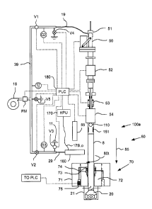
opening defined
by the walls. The outer wall may taper from an enlarged diameter to a reduced
diameter.
The outer wall may form an outer shoulder 251os and an inner shoulder 251is at
the
taper. The outer wall may have a radial port therethrough for each ball 256.
The outer
shoulder 251os may seat on a corresponding shoulder 221s formed in the case
port
221p. The balls 256 may seat in a corresponding groove 201g formed in the wall
defining the housing port 201, thereby fastening the body to the case 221. The
case port
221p may further include a taper 221r. The plug 250 may be shielded from
contacting
the wellbore by the taper 221r, thereby reducing risk of becoming damaged and
compromising sealing integrity. One or more seals, such as o-rings 253, may
seal an
interface between the plug body 251 and the case 221.
[0068] The locking sleeve 252 may be disposed in the body 251 between
the inner
and outer walls and may be longitudinally movable relative thereto. The
locking sleeve
252 may be retained in the body by a fastener, such as snap ring 254. The disc
spring
255 may be disposed between the locking sleeve and the body and may bias the
locking
sleeve toward the snap ring. An outer surface of the locking sleeve 252 may
taper to
form a recess 252r, an enlarged outer diameter 252od, and a shoulder 252os.
One or
more protrusions may be formed on the outer shoulder 252os to prevent a vacuum
from
forming when the outer shoulder seats on the body inner shoulder 251is. An
inner
surface of the locking sleeve may taper to form an inclined shoulder 252is and
a latch
profile 252p.
[0069] Figure 6B is a cross-sectional view of the clamp 300 for
removing and
installing the plug 250. The clamp 300 may include a hydraulic actuator, such
as a
retrieval piston 301 and a retaining piston 302; an end cap 303, a chamber
housing 304,
CA 02846749 2014-03-14
a piston rod 305, a fastener, such as a snap ring 306; one or more seals, such
as o-rings
306-311, 334, 336, 339; one or more fasteners, such as set screws 312, 313;
one or
more fasteners, such as nuts 314 and cap screws 315; one or more fasteners,
such as
cap screws 316; one or more fasteners, such as a tubular nut 317; one or more
clamp
bands 318,319; a clamp body 320; a clamp handle 321; a clamp latch 322; one or
more
handles, such as a clamp latching handle 323 and a clamp unlatching handle
325; one or
more springs, such as torsion spring 324 and coil spring 331; a rod sleeve
326; a flow
nipple 327; a hoist ring 328; a locator, such as dowel 329; a plug 330; a
tension adjuster,
such as bolt 332a and stopper 332b; one or more seals, such as rings 333; a
latch, such
as collet 335; one or more hydraulic ports 337, 338, and a fastener, such as
nut 340.
Alternatively, the clamp actuator may be pneumatic or electric. A more
detailed
discussion of the clamp components and operation thereof may be found in the
US
61/292,607 provisional at Figures 3, 3A, and 5A-E and the accompanying
discussion
therewith. Any of the deployment options and alternatives discussed above for
the
clamp 160 also apply to the clamp 300.
[0070] In operation, the RCFS 200 and the clamp 300 may be used in the
drilling
method, discussed above, instead of the RCFS 100 and the clamp 160. The HPU
170
may be modified (not shown) to operate the clamp 300.
[0071] Figure 7A is a cross-sectional view of a portion of an RCFS 400,
according to
another embodiment of the present invention. The RCFS 400 may be similar to
either of
the RCFSs 100, 200 except for the substitution of a bore float valve 410 for
the bore ball
valve 110 and accompanying modifications to the RCFS housing 105u (now 405u).
The
float valve 410 may include a closure member, such as a flapper 410f, a body
411, and a
locking sleeve 412. The body 411 may be disposed in a recess formed in the
upper
housing section 405u. The float valve 410 may be longitudinally coupled to the
housing
705 by disposal between shoulders 406u,1 formed in the upper housing section.
Alternatively, the upper shoulder 406u may be omitted and the float valve 410
may be
inserted into the upper housing section 405u via the box 405b and fastened to
the
housing 405u, such as by a threaded connection and a snap ring.
21
CA 02846749 2014-03-14
[0072] The locking sleeve 412 may have a shoulder 412s formed in an
inner surface
thereof and a fastener, such as a snap ring 412f, disposed in an outer surface
thereof.
The locking sleeve 412 may be movable between an unlocked position (shown) and
a
locked position. The locking sleeve 412 may be fastened to the body 411 in the
upper
position by one or more frangible fasteners, such as shear screws 411f. A seal
411s
may be disposed along an outer surface of the body 411. The flapper 410f may
be
pivoted 410p to the body 411 and movable between an open position and a closed
position (shown). The flapper 410f may be biased toward the closed position by
a
biasing member, such as a torsion spring (not shown). The flapper 410f may be
movable to an open position in response to fluid pressure above the flapper
exceeding
fluid pressure below the flapper (plus resistance by the torsion spring).
[0073] If a thru-tubing operation needs to be conducted through the
drill string 60,
such as to remediate a well control situation, a shifting tool (not shown) may
be deployed
using a deployment string, such as wireline, slickline, or coiled tubing. The
shifting tool
may include a plug having a shoulder corresponding to the locking sleeve
shoulder 412s
and a shaft extending from the plug. The shaft may push the flapper 410f at
least
partially open as the plug seats against the locking sleeve shoulder 412s and,
thereby
equalizing pressure across the flapper. Weight of the plug may then be applied
to the
shoulder 410s by relaxing the deployment string or fluid pressure may be
exerted on the
plug from the surface or through the deployment string.
[0074] The shear screws 411f may then fracture allowing the locking
sleeve 412 to be
moved longitudinally relative to the body 411 until the snap ring 412f engages
a groove
411g formed in an inner surface of the body. The locking sleeve 412 may engage
and
open the flapper 410f as the locking sleeve is being moved. The snap ring 412f
may
engage the groove 411g, thereby fastening the locking sleeve 412 in the locked
position
with the flapper 410f held open. The operation may be repeated for every RCFS
400
disposed along the drill string 60. In this manner, every RCFS 400 in the
drill string 60
may be locked open in one trip. Remedial well control operations may then be
22
=
CA 02846749 2014-03-14
conducted through the drill string in the same trip or retrieving the
deployment string to
surface and changing tools for a second deployment.
[0075] In operation, the RCFS 400 may be used in the drilling method,
discussed
above, instead of the RCFSs 100, 200. Since the float valve 410 may respond
automatically, the steps of manually opening and closing the bore valve 110
are
obviated. In a further alternative, the rotation stoppages of the drill string
at Figures 5B,
5C, 5G, and 5H may be omitted by connecting the clamp 160 before engaging the
slips
73 of the rotary table 70 (for 5B and 5C) and by disengaging the slips before
removing
the clamp (for 5G and 5H). Rotation of the drill string 60 may then be
continuously
maintained while adding the stand 62 to the drill string.
[0076] Figure 7B is a cross-sectional view of a portion of an RCFS 425,
according to
another embodiment of the present invention. The RCFS 425 may include one or
more
tubular housing sections 430t (upper housing section not shown, see 105u,
405u), a
bore valve (not shown, see 110, 410), and a port valve. The lower housing
section 430t
may have one or more radial ports 426 formed through a wall thereof. The
radial ports
426 may be circumferentially spaced around the lower housing section 430. The
RCFS
425 may be used with a modified clamp 440 equipped with a swivel, such as
rotary
sleeve 445 or rollers (not shown), allowing the housing 430t to rotate
relative to the
clamp. The port valve may include a sleeve 435 and a biasing member, such as a
spring
438. The sleeve 435 may be disposed in a recess formed in the lower housing
section
430t. The sleeve 435 may have a piston shoulder 435s having a seal 436 for
engaging
an inner surface of the lower housing section 430. The sleeve 435 may be
longitudinally
movable relative to the housing 430t between an open position and a closed
position.
The spring 438 may bias the sleeve 435 toward the closed position where the
sleeve
isolates the housing ports 426 from the housing bore. The clamp 440 may engage
the
housing 430t. When pressure is exerted on a flow passage 441 through the clamp
440,
the pressure may act on the piston shoulder 435s of the sleeve 435, thereby
pushing the
sleeve longitudinally from the closed position to the open position and
allowing side
circulation. When circulation through the side ports 426 is halted, the spring
438 may
23
. ,
CA 02846749 2014-03-14
return the sleeve 435 to the closed position. The RCFS 425 may further include
upper
431 and lower 432 seals for further isolating the ports 426 from the bore.
Alignment of
the clamp port 441 with the housing port 426 is not required for fluid
communication of
the ports.
[0077] Figure 7C is a cross-sectional view of a portion of an RCFS 450,
according to
another embodiment of the present invention. The RCFS 450 may include a
tubular
housing 455e (upper housing section not shown, see 105u, 405u), a bore valve
(not
shown, see 110, 410), a swivel 460, and a plug 250. The lower housing section
455e
may have a port 451 formed through a wall thereof in communication with the
bore. The
swivel 460 may include a sleeve 461, one or more bearings 462, and one or more
seals
463. The clamp 300 may engage the rotary sleeve 461 while the housing 455e may
rotate relative to the sleeve 461 and the clamp 300. To remove and install the
plug 250,
rotation of the RCFS 450 may be stopped so the clamp 300 may be aligned with
the port
451 to access the plug 250.
[0078] Figure 7D is a cross-sectional view of a portion of an RCFS 475,
according to
another embodiment of the present invention. The RCFS 475 may include a
tubular
housing 480e (upper housing section not shown, see 105u, 405u), a bore valve
(not
shown, see 110, 410), and a plug 250. The housing 480e may have a side port
481 and
the plug may be installed and removed from the side port. As compared to the
RCFS
450, the swivel has been omitted and the clamp 440 may be used with the RCFS
475
instead of the clamp 300.
[0079] Figure 8 is a cross-sectional view of an RCFS 500, according
to another
embodiment of the present invention. The RCFS 500 may include a non-rotating
CFS
(NCFS) 500a and a locking swivel 560. The NCFS 500a may be similar to the RCFS
100 except that the bearings 122u,e may be omitted so that the sleeve 521 does
not
rotate relative to the housing, the seals disposed between the housing and the
sleeve
521 do not have to accommodate rotation, and a bottom of the lower housing has
a
threaded coupling for connecting to the locking swivel 560 instead of a pin
for connecting
to a pup joint/drill pipe.
24
CA 02846749 2014-03-14
[0080] Figure 8A is an isometric view of the locking swivel 560. The
locking swivel
560 may include an upper housing 561 and a lower housing 562. The upper
housing
561 may include one or more lugs 561p extending from an outer surface thereof.
A lock
ring 563 may be disposed around an outer the outer surface of the upper
housing 561 so
that the lock ring 563 is longitudinally moveable along the upper housing 561
between an
unlocked position and a locked position. The lock ring 563 may include a key
563k for
each lug 561p. The lower housing 562 may include a keyway 562w for receiving a
respective lug 561p and a shoulder 562s for engaging a respective lug 561p
once the lug
561p has been inserted into the keyway 562w and rotated relative to the lower
housing
until the lug 561p engages the shoulder 562s. Once each lug 561p has engaged
the
respective shoulder 562s, the lock ring 563 may be moved into the locked
position,
thereby engaging each key 563k with a respective keyway 562w. The upper
housing 561
may include one or more holes laterally formed in an outer surface thereof,
each hole
corresponding to respective set of holes 563h formed through the lock ring
563.
Engaging the keys 563k with the keyways 562w may align the holes for receiving
a
respective fastener, such as pin 564, thereby fastening the upper housing 561
to the
lower housing 562. The lower housing 562 may further include a seal mandrel
562m
extending along an inner portion thereof. The seal mandrel 562m may include a
seal (not
shown) and a bearing (not shown) disposed along an outer surface for engaging
an inner
surface of the upper housing 561 to seal the interface therebetween and allow
relative
rotation of the lower housing 562 relative to the upper housing 561.
[0081] In operation, the RCFS 500 may be used in the drilling method,
discussed
above, instead of the RCFS 100. The locking swivel 560 may be unlocked during
the
first rotation stoppage. The rotary table 70 may then rotate the drill string
60 excluding
the upper housing 561 and NCFS 500a which may remain rotationally stationary.
The
locking swivel 560 may then be locked during the second rotation stoppage.
[0082] Alternatively, the NCFS 500a may be used in a non-rotating
continuous flow
drilling method (without the locking swivel and having the conventional pin
coupling at a
bottom of the lower housing).
CA 02846749 2014-03-14
[0083] Figures 9A-9D are cross-sectional views of wellbores 800, 810,
820, 830 being
drilled with drill strings 802 employing downhole RCFSs 805, 825a,b, according
to other
embodiments of the present invention.
[0084] Referring to Figure 9A, the wellbore 800 may have a tubular
string of casing
801c cemented therein. A tubular liner string 8011 may be hung from the casing
801c by
a liner hanger 801h. The liner hanger may include a packer for sealing the
casing-liner
interface. The liner 8011 may be cemented in the wellbore 800. A tieback
casing string
801t may be hung from a wellhead (not shown, see Figure 1) and may extend into
the
wellbore 800 proximately short of the hanger 801h so that a flow path is
defined between
the distal end of the tieback string 801t and the liner hanger 801h or top of
the liner 8011.
Alternatively, a parasite string may be used instead of the tieback string
801t. A drill
string 802 may extend from a top drive or Kelly located at the surface (not
shown, see
Figure 1). The drill string 802 may include a drill bit 803 located at a
distal end thereof
and a CFS 805.
[0085] The RCFS 805 may include a tubular housing have a longitudinal flow
bore
therethrough and a radial port through a wall thereof. A float valve 805f may
be disposed
in the housing bore and may be similar to the float valve 410. A check valve
805c may
be disposed in the housing port. The check valve 805c may be operable between
an
open position in response to external pressure exceeding internal pressure
(plus spring
pressure) and a closed position in response external pressure being less than
or equal to
internal pressure. The check valve 805c may include a body, one or more seals
for
sealing the housing-port interface, a valve member, such as a ball, flapper,
poppet, or
sliding sleeve and a spring disposed between the body and the valve member for
biasing
the valve member toward a closed position.
[0086] The RCFS 805 may further include an annular seal 805s. The annular
seal
805s may engage an outer surface of the CFS housing and an inner surface of
the tie-
back string 805t so that an upper portion of an annulus formed there-between
is isolated
from a lower portion thereof. The annular seal 805s may be longitudinally
positioned
below the check valve 805c so that the check valve is in fluid communication
with the
26
CA 02846749 2014-03-14
upper annulus portion. A cross-section of the annular seal may take any
suitable shape,
including but not limited to rectangular or directional, such as a cup-shape.
The annular
seal 805s may be configured to engage the tie-back string only when drilling
fluid is
injected into the tie-back/drill string annulus, such as by using the
directional
configuration. The annular seal may be part of a seal assembly that allows
rotation of
the drill string relative thereto.
[0087] The seal assembly may include the annular seal, a seal mandrel,
and a seal
sleeve. The seal mandrel may be tubular and may be connected to the CFS
housing by
a threaded connection. The seal sleeve may be longitudinally coupled to the
seal
mandrel by one or more bearings so that the seal sleeve may rotate relative to
the seal
mandrel. The annular seal may be disposed along an outer surface of the seal
sleeve,
may be longitudinally coupled thereto, and may be in engagement therewith. An
interface between the seal mandrel and seal sleeve may be sealed with one or
more of a
rotating seal, such as a labyrinth, mechanical face seal, or controlled gap
seal. For
example, a controlled gap seal may work in conjunction with mechanical face
seals
isolating a lubricating oil chamber containing the bearings. A balance piston
may be
disposed in the oil chamber to mitigate the pressure differential across the
mechanical
face seals.
[0088] Additionally, the CFS port may be configured with an external
connection. The
external connection may be suitable for the attachment of a hose or other such
fluid line.
The annular seal 805s may also function as a stabilizer or centralizer.
[0089] The CFS 805 may be assembled as part of the drill string 802
within the
wellbore 800. Once the CFS 805 is within the tie-back string 805t, drilling
fluid 804f may
be injected from the surface into the tieback/drill string annulus. The
drilling fluid 804f
may then be diverted by the seal 805c through the check valve 805c and into
the drill
string bore. The drilling fluid may then exit the drill bit 803 and carry
cuttings from the
bottomhole, thereby becoming returns 804r. The returns 804r may travel up the
open
wellbore/drill string annulus and through the liner/drill string annulus. The
returns 804r
may then be diverted into the casing/tie-back annulus by the annular seal
805s. The
27
CA 02846749 2014-03-14
returns 804r may then proceed to the surface through the casing/tie-back
annulus. The
returns may then flow through a variable choke valve (not shown), thereby
allowing
control of the pressure exerted on the annulus by the returns.
[0090] Inclusion of the additional tie-back/drill string annulus
obviates the need to
inject drilling fluid through the top drive. Thus, joints/stands may be
added/removed
to/from the drill string 802 while maintaining drilling fluid injection into
the tie-back/drill
string annulus. Further, an additional CFS 805 is not required each time a
joint/stand is
added to the drill string. During drilling, drilling fluid may be injected
into the top drive
and/or the tie-back/drill string annulus. If drilling fluid is injected into
only the top drive,
the drilling fluid may be diverted to the tie-back/drill string annulus when
adding/removing
a joint/stand to/from the drill string. The tie-back/drill string annulus may
be closed at the
surface while drilling. If drilling fluid is injected into only the tie-
back/drill string, injection
of the drilling fluid may remain constant regardless of whether drilling or
adding/removing
a stand/joint is occurring.
[0091] Referring to Figure 9B, the RCFS 805 may also be deployed for
drilling a
wellbore 810 below a surface 812s of the sea 812. A tubular riser string 801r
may
connect a fixed or floating drilling rig (not shown), such as a jack-up, semi-
submersible,
barge, or ship, to a wellhead 811 located on the seafloor 812f. A conductor
casing string
801cc may extend from the wellhead 811 and may be cemented into the wellbore.
A
surface casing string 801sc may also extend from the wellhead 811 and may be
cemented into the wellbore 810. A tubular return string 801p may be in fluid
communication with a riser/drill string annulus and extend from the wellhead
811 to the
drilling rig. The riser/drill string annulus may serve a similar function to
the tie-back/drill
string annulus discussed above. The surface casing string/drill string annulus
may serve
a similar function to the liner/drill string annulus, discussed above. The
returns 804r,
instead of being diverted into the casing/tie-back annulus may be instead
diverted into
the return string.
[0092] Alternatively, the riser string may be concentric, thereby
obviating the need for
the return string 801p. A suitable concentric riser string is illustrated in
Figures 3A and
28
CA 02846749 2014-03-14
3B of International Patent Application Pub. WO 2007/092956 (Atty. Dock. No.
WEAT/0730-PCT, hereinafter '956 PCT). The concentric riser string may include
riser
joints assembled together. Each riser joint may include an outer tubular
having a
longitudinal bore therethrough and an inner tubular having a longitudinal bore
therethrough. The inner tubular may be mounted within the outer tubular. An
annulus
may be formed between the inner and outer tubulars.
[0093] Referring to Figure 90, the subsea wellbore 820 may be drilled
using the CFS
825a instead of the CFS 805. The CFS 825a may differ from the CFS 805 by
removal of
the annular seal 805s. Instead, a rotating control device (RCD) 821 may be
used to
divert the drilling fluid 904f into the drill string and the returns 804r into
the returns string
801p. Instead of longitudinally moving with the drill string 802, the RCD 821
may be
longitudinally connected to the wellhead 811.
[0094] Figure 9D illustrates the bottom of the wellbore 820 extended to
a second,
deeper depth relative to Figure 90. Once the CFS 825a nears the RCD 821, a
second
CFS 825b may be added to the drill string 802. The second CFS 825b may
continue the
function of the CFS 825a. Once drilling fluid 804f is diverted into the drill
string 802, the
drilling fluid may open the float valve 805f in the CFS 825a and close the
check valve
805c in the CFS 825a. Since the CFS 825a may not include the annular seal
805s, the
CFS 825a may pass through the RCD 821 unobstructed.
[0095] In operation, any of the downhole CFSs 805, 825a,b may be used in
the
drilling method, discussed above, instead of the RCFS 100. Use of the downhole
CFSs
may obviate the rotation stoppages of the drill string at Figures 5B, 50, 5G,
and 5H.
Rotation of the drill string may then be continuously maintained while adding
the stand to
the drill string.
[0096] Figure 9E is a cross-sectional view of one embodiment of the RCD
821. The
RCD 821 may be located and secured within a housing 864 which includes a head
860
and a body 862. In the illustrated embodiment, the RCD 821 is removably held
in place
by a packing unit 868 energized by piston 866 within the housing 864.
Alternatively, the
29
CA 02846749 2014-03-14
RCD may be removably secured with the housing 864 using an appropriate latch,
or the
RCD 821 may be permanently secured within the housing 864.
[0097] The RCD 821 may further include a bearing assembly 878. The
bearing
assembly 878 may be attached to at least one of a top stripper rubber 882 and
a bottom
stripper rubber 884. The bearing assembly 878 allows stripper rubbers 882, 884
to
rotate relative to the housing 864. Each rubber 882, 884 may be directional
and the
upper rubber 882 may be oriented to seal against the drill string 802 in
response to
higher pressure in the riser 801r than the wellbore 820 and the lower rubber
884 may be
oriented to seal against the drill string in response to higher pressure in
the wellbore than
the riser. In operation, the drill string 802 can be received through the
bearing assembly
878 so that one of the rubbers 882, 884 may engage the drill string depending
on the
pressure differential. The RCD 821 may provide a desired barrier or seal in
the riser 801r
both when the drill string 802 is stationary or rotating. Alternatively, an
active seal RCD
may be used.
[0098] While the foregoing is directed to embodiments of the present
invention, other
and further embodiments of the invention may be devised without departing from
the
basic scope thereof, and the scope thereof is determined by the claims that
follow.