Note: Descriptions are shown in the official language in which they were submitted.
CA 02846886 2014-03-17
WING FLAPPING MECHANISM AND METHOD
CROSS-REFERENCE
The present case claims the benefit of U.S. Patent Application No. 61/793,335
filed on 15 March
2013.
TECHNICAL FIELD
The technical field relates generally to wing flapping mechanisms for use in
flying machines such
as ornithopters and orthopters. It also relates to methods of propelling
flying machines using
flapping wings.
BACKGROUND
Many artificial mechanisms have been suggested in the past in an attempt to
imitate the way birds,
insects and other animals with wings are flying. This resulted in a number of
different
constructions. Some of these mechanisms were designed for use in mechanical
bird toys while
others were designed for use in much larger implementations. However, existing
approaches have
limitations preventing the wing flapping motions from being fully optimized
during a flight. Thus,
they are only partially successful in addressing the challenge of creating
wing flapping mechanisms
that are truly capable of flying as some animals do, particularly birds.
Examples of suggested mechanisms can be found in documents such as U.S. Patent
Application
Publication No. 2002/0117583 Al published 29 August 2002 to Hamamoto et al.,
U.S. Patent
No. 7,651,051 B2 issued 26 January 2010 to Agrawal et al., German Patent
Application No.
DE 10 2009 015 974 Al published on 30 September 2010 to FESTO AG & CO, and
U.S. Patent
CA 02846886 2014-03-17
2
Application Publication No. 2012/0003896 published 5 January 2012 to Van
Ruymbeke, to name
just a few.
Overall, there is still room for many improvements in this area of technology.
SUMMARY
The proposed concept provides a new approach in wing flapping mechanisms for
use in flying
machines such as ornithopters and orthopters.
In one aspect, there is provided a wing flapping mechanism including: a main
frame extending
along a longitudinal axis; a pair of opposite wing structures laterally
projecting from the main
frame, each wing structure including: a triaxial shoulder joint having a
proximal end and a distal
end, the proximal end of the shoulder joint being pivotally connected to a
respective side of the
main frame; a first torsion-responsive tube having a proximal end and a distal
end, the proximal
end of the first torsion-responsive tube being rigidly connected to the distal
end of the shoulder
joint; an uniaxial elbow joint having a proximal end and a distal end, the
proximal end of the elbow
joint being rigidly connected to the distal end of the first torsion-
responsive tube; a second torsion-
responsive tube having a proximal end and a distal end, the proximal end of
the second torsion-
responsive tube being rigidly connected to the distal end of the elbow joint;
a biaxial wrist joint
having a proximal end and a distal end, the proximal end of the wrist joint
being rigidly connected
to the distal end of the second torsion-responsive tube; and a third torsion-
responsive tube having
a proximal end and a distal end, the proximal end of the third torsion-
responsive tube being rigidly
connected to the distal end of the wrist joint; and a linkage arrangement to
convert rotation of a
motor into a three-dimensional cyclic wing motion of each of the wings, the
linkage arrangement
including torque-transmitting couplings extending from inside the main frame
into the wing
CA 02846886 2014-03-17
3
structures to transmit an alternating pivoting motion, created as a result of
the rotation of the motor,
to the distal end of a corresponding one of the third torsion-responsive
tubes, each torque-
transmitting coupling extending inside the shoulder joint, the first torsion-
responsive tube, the
elbow joint, the second torsion-responsive tube, the wrist joint and the third
torsion-responsive tube
of the corresponding wing structure.
In another aspect, there is provided a wing flapping mechanism including: a
motor, for instance an
electric motor, having a unidirectional rotatable output shaft; three spaced-
apart rotatable axles that
are mechanically connected to the unidirectional rotatable output shaft, the
rotatable axles having
a same rotation speed and direction during operation of the motor, each full
rotation of the rotatable
axles corresponding to a wing flapping cycle; and a reciprocately-movable axle
that is
mechanically connected to the unidirectional rotatable output shaft, the
reciprocately-movable axle
having a pivoting motion synchronized with the rotation of the rotatable axles
and being repeated
at each wing flapping cycle.
In another aspect, there is provided a method of transmitting an alternating
pivoting motion to a tip
of a wing of a wing flapping flying machine using a set of juxtaposed and
interconnected torsion-
inducing tubes coaxially disposed inside a corresponding set of juxtaposed and
interconnected
torsion-responsive tubes, the alternating pivoting motion being transmitted
between the torsion-
inducing tubes regardless of a spatial orientation of the torsion-inducing
tubes and of the torsion-
responsive tubes.
In another aspect, there is provided a method of generating a wing flapping
motion using a wing
flapping mechanism provided on a flying machine having two opposite wings, the
wing flapping
mechanism being capable of creating a sustained flight of the flying machine
using mechanical
CA 02846886 2014-03-17
4
motor power, the wing flapping mechanism driving each wing into a 3D cyclic
motion that is a
combination of five sub-motions imposed to three juxtaposed and non-
collinearly disposed wing
segments.
In another aspect, there is provided a method of propelling a flying machine
using flapping wings
extending from a main frame, each wing including three juxtaposed and non-
collinearly disposed
wing structure segments, the method including: generating a cyclic three-
dimensional flapping
motion of each wing; and simultaneously generating a cyclic alternating
pivoting sub-motion at a
tip of each wing regardless of a relative position of the corresponding wing
structure segment.
The proposed concept can also provide a wing flapping mechanism inducing
progressive twisting
from wing tip to wing base by three juxtaposed torsion-inducing tubes coming
from main frame
joined to three juxtaposed torsion responsive tubes going back to main frame
by a locking pin.
The proposed concept can also provide a lever arm and push-pull rod assembly
converting rotation
into alternating translation motion in a vertical axis (Z-axis), the push-pull
rod being attached to a
second shoulder sub-component to make it alternatively pivot around a
longitudinal axis (X-axis)
in a transversal Y-Z plane so as to generate a flapping sub-motion.
The proposed concept can also provide a lever arm and push-pull rod assembly
converting rotation
into alternating translation motion in a longitudinal axis (X-axis), the push-
pull rod being attached
to a third (distal) shoulder sub-component to make it alternatively pivot
around a vertical axis (Z-
axis) in a horizontal X-Y plane so as to generate a forward-rearward sub-
motion.
The proposed concept can also provide a pair of push-pull rods so as to
generate a folding-
deployment sub-motion, a first one of these push-pull rods being connected to
a second shoulder
CA 02846886 2014-03-17
sub-component and to a second rod via an extension of a proximal elbow sub-
component, the
second push-pull rod connecting the distal end of the first rod to a distal
segment of the wrist joint
holding a third wing segment, the pair of push-pull rods forcing three wing
segments to fold or
deploy on themselves in a lateral axis (Y-axis) within an horizontal plane X-
Y, the pair of push-
The proposed concept can also provide a lever arm and push-pull rod assembly
converting rotation
into an alternating translation motion in a vertical axis (Z-axis), the push-
pull rod being attached to
a first (proximal) shoulder sub-component to make it alternatively pivot
around a lateral axis (Y-
The proposed concept can also provide a lever arm and push-pull rod assembly
converting rotation
into an alternating translation motion and then into an alternating pivoting
motion around a lateral
axis (Y-axis) so as to generate a progressive wing twisting sub-motion, the
alternating pivoting
motion being transmitted through each wing via three juxtaposed torsion-
inducing tubes joined
belts and pulleys that are configured and disposed so as to generate a three-
dimensional (3D) cyclic
CA 02846886 2014-03-17
6
motion of wing segments, the 3D motion being a combination, for instance, of
the five sub-motions
previously defined.
The proposed concept can also provide a central mechanism allowing adjustments
so as to achieve
angular advances and/or angular delays of one or more sub-motions in a 3D
cyclic motion, for
instance one or more of the five sub-motions previously defined.
The proposed concept can also provide a central mechanism allowing amplitude
optimization
independently for each one of the five sub-motions previously defined.
The proposed concept can also provide a mechanism for flapping wings that
includes a motor, for
instance an electric motor, and a mechanical power distribution system having
four axles in
continuous rotation and one axle that is in an alternating pivoting motion,
all axles being
mechanically synchronized during each wing flapping cycle.
The proposed concept can also provide a mechanism for flapping wings using
lever arms (cranks)
and corresponding push-pull rods to generate translation motions, including
one creating an
alternating pivoting motion, all of them being synchronized during each wing
flapping cycle and
having the possibility to be adjusted in amplitude upon changing the position
of the connection
points of the push-pull rods on the lever arms during operation.
The proposed concept can also provide a mechanism for flapping wings
generating a wing flapping
motion by the use of a lever arm and push-pull rod mechanism attached to
shoulder components.
The proposed concept can also provide a mechanism for flapping wings that is:
CA 02846886 2014-03-17
7
- generating a progressive alternating pivoting motion using a lever arm and
push-pull rod
mechanism that interconnects to another one in a way to convert a translation
motion into the
alternating pivoting motion around a lateral axis that can be amplified via a
pulley stage linked to
the axis of a first torsion-inducing tube; and/or
- generating a progressive alternating pivoting motion from wing tip to wing
base via three non-
collinear segments, each made of two concentric tubes, the inside one being
the "torsion inducer"
and the outside tube being the "torsion responder" and each pivoting around
the lateral axis or close
to it (the torsion-inducing tube being rigid in torsion and the torsion-
responsive tube being flexible
in torsion), each non-collinear segments being joined by articulations as
shoulder-elbow-wrist for
the outside tube and flexible members for the inside tubes, the stiffness of
the wing structure being
enhanced by the inner tube via the articulations of the outer tubes.
The proposed concept can also provide a mechanism for flapping wings that can
generate wing
longitudinal/folding/flapping sub-motions using a lever arm and push-pull rod
mechanism attached
at the base of shoulder-elbow segment, shoulder components moving around a
longitudinal and
vertical coincident axes of rotation, a shoulder-to-elbow segment,
interconnecting rods from
shoulder to elbow and from elbow to wrist, elbow components around a vertical
axis and then wrist
components pivoting around longitudinal and vertical axes, and component being
moved around
longitudinal axis by a push-pull rod to contribute to the folding sub-motion
in a proportional way
of the flapping sub-motion.
The proposed concept can also provide a mechanism for flapping wings having a
wing base
pivoting motion using a lever arm and push-pull rod mechanism attached to a
first shoulder
component and pivoting around a lateral axis.
CA 02846886 2014-03-17
8
The proposed concept can also provide a mechanism for flapping wings having
shoulder
components pivoting around a longitudinal axis and that are mounted on other
shoulder
components pivoting around a lateral axis.
The proposed concept can also provide a mechanism for flapping wings having
shoulder
components pivoting around a vertical axis and that are mounted on other
shoulder components
pivoting around a longitudinal axis and a lateral axis.
The proposed concept can also provide a mechanism for flapping wings having a
lateral "torsion-
inducing tube" axis running through three shoulder coincident axes
(longitudinal, vertical and
lateral), the elbow's single vertical axis, and the wrist's two non-coincident
longitudinal and
vertical axes. It should be noted, however, that the two axes of the wrist
joint can be made
coincident in some implementations.
The proposed concept can also provide a mechanism for flapping wings using a
linear guiding
system with an endless screw to adjust the lever arms so as to adjust the
amplitude of one or more
of the sub-motions, for instance for takeoff, stable flight and landing
conditions.
The proposed concept can also provide a mechanism for flapping wings having a
wing covering
supported in each of the three wing's sections by at least spaced-apart two
ribs, each mounted on
a corresponding torsion-responsive tube.
The proposed concept can also provide the possibility of using one or more
structural extrados
airfoil sections as torsion-responsive tubes.
CA 02846886 2014-03-17
9
The proposed concept can also provide a mechanism for flapping wings having
wing airfoil
sections overlapping one another in a way that each section tip support itself
on the other one during
the wing down stroke of the flapping cycle.
The proposed concept can also provide a mechanism for flapping wings offering
the possibility of
having a wing tip flap extension for low speed flights by using an extended
portion of a push-pull
rod to actuate a second rod connected to the wing tip flap extension, the wing
tip flap extension
pivoting on the wing structure, thus creating three new pivot points.
The technology presented herein can be used in many different fields and for a
wide range of
applications. Non-limiting examples of potential fields and applications
include robotics, toys,
military drones, animatronics (for motion pictures, exhibitions, theme or
amusement parks or the
like), art kinetic structures and educational presentations. Numerous others
exist.
Details on these aspects as well as other aspects of the proposed concept will
be apparent from the
following detailed description and the appended figures.
BRIEF DESCRIPTION OF THE FIGURES
FIG. 1 is a semi-schematic view of an example of a wing flapping mechanism as
suggested herein,
the wing flapping mechanism being provided inside an example of a generic
mechanical bird;
FIG. 2 is a top view of the left wing on the mechanical bird shown in FIG. 1;
FIG. 3 is an isometric side view illustrating the main frame and the left wing
structure of the wing
flapping mechanism shown in FIG. 1;
FIG. 4 is a semi-schematic left side view of the wing flapping mechanism shown
in FIG. 3;
CA 02846886 2014-03-17
FIG. 5 is a top view of the left wing structure of the wing flapping mechanism
shown in FIG. 3;
FIG. 6 is a front view of the left wing structure shown in FIG. 5;
FIG. 7 is another top view of the left wing structure shown in FIG. 5;
FIG. 8 is an isometric rear view of the proximal portion of the left wing
structure of the wing
5 flapping mechanism shown in FIG. 3;
FIG. 9 is a vertical cross-sectional rear view of the left shoulder joint of
the wing flapping
mechanism shown in FIG. 3;
FIG. 10A is a semi-schematic view of the left third torsion-responsive tube of
the wing flapping
mechanism shown in FIG. 3 to illustrate the effect of the torque being applied
at the distal end
10 thereof;
FIG. 10B is a view similar to FIG. 10A, showing an alternative configuration;
FIG. 10C is a view similar to FIG. 2, showing another alternative
configuration;
FIG. 11 is an isometric top view of the left elbow joint of the wing flapping
mechanism shown in
FIG. 3;
FIG. 12 is an isometric bottom view of the left elbow joint shown in FIG. 11;
FIG. 13 is an isometric top view of the left wrist joint of the wing flapping
mechanism shown in
FIG. 3;
FIG. 14 is an isometric bottom view of the left wrist joint shown in FIG. 13;
CA 02846886 2014-03-17
11
FIGS. 15A to 15H are side views of the left wing structure of the wing
flapping mechanism shown
in FIG. 3 during an example of a complete wing flapping cycle;
FIGS. 16A to 16H are front views of the left wing structure of the wing
flapping mechanism shown
in FIG. 3, each view A to H corresponding in position to what is shown in
FIGS. 15A to 15H,
respectively;
FIGS. 17A to 17H are top views of the left wing structure of the wing flapping
mechanism shown
in FIG. 3, each view A to H corresponding in position to what is shown in
FIGS. 15A to 15H,
respectively;
FIG. 18 is an isometric and semi-schematic view illustrating an example of an
arrangement for
repositioning the end of a push-pull rod on a corresponding lever arm; and
FIGS. 19 and 20 are top views of the left wing of the mechanical bird shown in
FIG. Ito illustrate
an example of an optional wing extension.
DETAILED DESCRIPTION
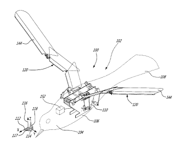
FIG. I is a semi-schematic view of an example of a wing flapping mechanism 100
as suggested
herein. This wing flapping mechanism 100 is provided inside an example of a
generic mechanical
bird 102. Such mechanical bird 102 can also be called an ornithopter or an
orthopter.
FIG. 1 is only an example of a possible implementation. The wing flapping
mechanism 100 can
also be used with other kinds of flying machines using flapping wings,
including ones that are not
shaped as birds or the like. The flying machines can be significantly larger
in size than birds as
well. Still, the wing flapping mechanism 100 could be used in machines that
are not capable of
CA 02846886 2014-03-17
12
flying for real. Non-limiting examples of potential fields and applications
include robotics, toys,
military drones, animatronics (for motion pictures, exhibitions, theme or
amusement parks or the
like), art kinetic structures and educational presentations. Numerous others
exist.
The illustrated mechanical bird 102 includes a head section 104, a main body
106, a tail section
108 and two opposite wings 120. It has a substantially symmetric construction
with reference to
the lengthwise direction, i.e. the left side and the right side being
substantially symmetric in
construction.
The wing flapping mechanism 100 includes a central main frame 110 that is
generally extending
along a longitudinal axis 112 and that is located inside the main body 106 of
the mechanical bird
102. The longitudinal axis 112 is substantially coextensive with the
lengthwise direction of the
mechanical bird 102. This longitudinal axis 112 corresponds to the X-axis in
the figures. The lateral
axis 114 (left to right or right to left) corresponds to the Y-axis in the
figures. The vertical axis 116
corresponds to the Z-axis in the figures. The main frame 110 includes two
spaced-apart main plates
160. The plates 160 extend parallel to one another and also parallel to the
longitudinal axis 112.
Laterally-extending spacer bars 162 are attached in-between the plates 160 at
various locations.
Variants are possible as well. FIG. 1 further illustrates the horizontal X-Y
plane 117 and the
transversal Y-Z plane 118.
FIG. 2 is a top view of the left wing 120 of the mechanical bird 102 shown in
FIG. 1. The right
wing 120 is substantially a mirror image of the left wing 120 of FIG. 2. Thus,
although the
following explanations about the wing structures are referring to the
illustrated left wing structure
122, they are also applicable to the right wing structure 122.
CA 02846886 2014-03-17
13
The wing flapping mechanism 100 includes a pair of opposite wing structures
122 laterally
projecting from the main frame 110. One is the right wing structure and the
other is the left wing
structure. Both wing structures 122 have a construction that is substantially
a mirror image of the
other.
FIG. 3 is an isometric side view illustrating the main frame 110 and the left
wing structure 122 of
the wing flapping mechanism 100.
FIG. 4 is a semi-schematic left side view of the wing flapping mechanism 100.
FIG. 5 is a top view of the left wing structure 122 of the wing flapping
mechanism 100.
FIG. 6 is a front view of the left wing structure 122 shown in FIG. 5.
FIG. 7 is another top view of the left wing structure 122 shown in FIG. 5.
As can be seen, each wing structure 122 is made of a plurality of parts
interconnected to one
another. In the illustrated example, it includes a triaxial shoulder joint
130, a first torsion-
responsive tube 132, a uniaxial elbow joint 134, a second torsion-responsive
tube 136, a biaxial
wrist joint 138 and a third torsion-responsive tube 140. The various joints
130, 134, 138 of each
wing structure 122 are named herein according to the relative position of
analogous parts in birds.
This is only for the sake of clarity.
Each part of the wing structure 122 includes a proximal end and a distal end.
It should be noted at
this point that the expressions "proximal end" and "distal end" are referring
to the relative position
of these opposite ends with reference to the main frame 110.
CA 02846886 2014-03-17
14
As can be seen in FIGS. 2 to 7, the proximal end of the shoulder joint 130 is
pivotally connected
to the side of the corresponding plate 160 of the main frame 110. More details
about the
construction of the shoulder joint 130 will be given later in the text.
The proximal end of each first torsion-responsive tube 132 is rigidly
connected to the distal end of
the corresponding shoulder joint 130. The first torsion-responsive tube 132
has an elongated and
rectilinear shape in the illustrated example. It also has a hollow cylindrical
body with an inner
circular cross section. Variants are possible as well.
The second torsion-responsive tube 136 has a proximal end and a distal end.
The proximal end of
the second torsion-responsive tube 136 is rigidly connected to the distal end
of the corresponding
elbow joint 134. The second torsion-responsive tube 136 has an elongated and
rectilinear shape in
the illustrated example. It also has a hollow cylindrical body with an inner
circular cross section.
Variants are possible as well.
The third torsion-responsive tube 140 has a proximal end and a distal end. The
proximal end of the
third torsion-responsive tube 140 is rigidly connected to the distal end of
the wrist joint 138. The
third torsion-responsive tube 140 has an elongated and rectilinear shape in
the illustrated example.
It also has a hollow cylindrical body with an inner circular cross section.
Variants are possible as
well.
The wing structure 122 is generally extending along the lateral axis 114.
However, most of time
during the motion of the wings 120, and as best shown from the top in FIGS. 2,
5 and 7, the distal
end of the first torsion-responsive tube 132 is slightly towards the rear with
reference to the
proximal end thereof, the distal end of the second torsion-responsive tube 136
is slightly towards
the front with reference to the proximal end thereof, and the distal end of
the third torsion-
CA 02846886 2014-03-17
responsive tube 140 is slightly towards the rear with reference to the
proximal end thereof. Thus,
when viewed from the top, the wing structure 122 has a somewhat zigzag shape.
In the illustrated example, spaced-apart ribs 142 are rigidly connected to the
outer surface of the
first torsion-responsive tube 132, the second torsion-responsive tube 136 and
the third torsion-
5 responsive tube 140 to support of corresponding set of three distinct
juxtaposed airfoil sections
144, as shown for instance in FIG. 2. There are at least two ribs 142 for each
portion of the wing.
Each rib 142 is substantially arc-shaped to give the shape to the airfoil
sections 144. Each rib 142
is also orthogonal with reference to the corresponding tube. The skin of the
airfoil sections 144 can
be made of a sheet-like material. This skin can be provided at the top of the
airfoil sections 144 or
10 on both sides (top and bottom) of the airfoil sections 144. Other
variants are possible as well.
In the illustrated example, the airfoil sections 144 are overlapping one
another in a way that each
section tip support itself on the other one during a complete wing flapping
cycle. Many variants
are possible as well. For instance, depending on the implementations, the
spaces between the airfoil
sections 144 can remain open and/or be covered with an elastic material of the
like. Still, the airfoil
15 sections 144 may also include a more complex construction in some
implementations and also be
designed as structural extrados airfoil sections (see for instance in FIG.
10C) to replace
corresponding ones of the torsion-responsive tubes 132, 136, 140 shown in FIG.
3. Other variants
are also possible.
The illustrated wing flapping mechanism 100 further includes a single electric
motor 150 to
generate the mechanical torque upon rotation of the motor 150 and thus drive
the two wing
structures 122 into motion. The motor 150 is located inside the main frame 110
and is supported
using internal brackets or the like. The motor 150 is schematically
illustrated in FIG. 4. The motor
CA 02846886 2014-03-17
16
150 is powered using one or more batteries 152 located inside the main body
106 of the mechanical
bird 102. Variants are also possible. For instance, one can design the wing
flapping mechanism
100 with two or more motors, such as with one motor per side for providing the
mechanical motor
power to a corresponding one of the wing structures 122. These motors could be
synchronized
electronically. One can also provide more than one motor driving a same
mechanical output for the
sake of redundancy. Still, one could use a plurality of servomotors to drive
each axle or some of
the axles independently from one another. Some implementations can include an
internal
combustion engine for generating the mechanical torque and/or for powering the
electric motor(s)
150 and any servomotor through a generator or the like. In relatively small
implementations, for
instance toys, the motor(s) 150 can be in the form of one or more spring-
loaded mechanisms or the
like. Many other variants are possible as well.
To increase the output torque and decrease its rotation speed, the motor 150
includes a speed-
reduction transmission 170 or another suitable similar arrangement that is
mechanically connected
between the rotor inside the motor 150 and an output shaft 154 that is
laterally disposed inside the
two spaced-apart main plates 160 of the main frame 110. The speed-reduction
transmission 170
can include a set of gears, for instance a planetary gear train or the like.
Variants are possible as
well.
FIG. 8 is an isometric rear view of the left wing structure 122.
FIG. 9 is a vertical cross-sectional rear view of the proximal portion of the
left wing structure 122.
As can be seen in FIGS. 8 and 9, each shoulder joint 130 includes three
juxtaposed subsections
130a, 130b, 130c that are pivotally connected to one another. The first
shoulder joint subsection
130a defines the proximal end of the shoulder joint 130 and is pivotally
connected to the
CA 02846886 2014-03-17
17
corresponding side of the main frame 110 around a first pivot axis 130d. This
first pivot axis 130d
extends substantially parallel to the lateral axis 114 (Y-axis). Thus, when
viewed from the side, the
first shoulder joint subsection 130a pivots clockwise and counterclockwise
around the first pivot
axis 130d.
The illustrated first shoulder joint subsection 130a includes a main plate
member 130a' extending
parallel and adjacent to the corresponding one of the plates 160 of the main
frame 110. It also
includes two flanged members 130a" provided at opposite front and rear ends of
the main plate
member 130a' and projecting perpendicularly in the outward direction. Variants
are possible as
well.
The illustrated second shoulder joint subsection 130b is pivotally connected
to the corresponding
first shoulder joint subsection 130a around a second pivot axis 130e. This
second pivot axis 130e
extends substantially parallel to the longitudinal axis 112 (X-axis) in the
illustrated example, i.e.
the second pivot axis 130e extends substantially parallel to the longitudinal
axis 112 when the first
shoulder joint subsection 130a is at a neutral position. A large part of the
up and down motions of
the corresponding wing 120 will come from motions around the second pivot axis
130e.
Also, the illustrated second shoulder joint subsection 130b is in the form of
a box-shaped member
opened on the outward-facing side thereof and whose opposite ends are
connected to the flanged
members 130a" of the first shoulder joint subsection 130a. Variants are also
possible.
The third shoulder joint subsection 130c defines the distal end of the
shoulder joint 130 and is
pivotally connected to the corresponding second shoulder joint subsection 130b
around a third
pivot axis 130f. The third pivot axis 130f extends substantially orthogonal
with reference to both
the first pivot axis 130d and the second pivot axis 130e. A large part of the
forward and rearward
CA 02846886 2014-03-17
18
motions around the vertical axis 116 (Z-axis) of the corresponding wing 120
will come from
motions around the third pivot axis 130f. The third shoulder joint subsection
130c includes a socket
member 130c' that is partially inserted inside the second shoulder joint
subsection 130b. The third
shoulder joint subsection 130c projects substantially outward from the second
shoulder joint
subsection 130b. Variants are possible as well.
Also, in the illustrated example, the first, second and third pivot axes 130d,
130e, 130f of each
shoulder joint 130 are substantially intersecting one another.
In the illustrated example, the proximal end of each first torsion-responsive
tube 132 is inserted
inside and rigidly connected to the socket member 130c' of the corresponding
third shoulder joint
subsection 130c.
The wing flapping mechanism 100 includes a linkage arrangement to convert
rotation of the motor
150 into a three-dimensional (3D) cyclic wing motion of each of the wing
structure 122. The
linkage arrangement of the illustrated example includes parts that are located
inside the main frame
110 and parts that are located outside the main frame 110.
In the illustrated example, the first sub-motion is the flapping sub-motion
created when the second
shoulder joint subsection 130b pivots around the longitudinal axis 112 (X-
axis). The second sub-
motion is the forward-rearward sub-motion created when the third shoulder
joint subsection 130c
pivots around the vertical axis 116 (Z-axis). The third sub-motion is the
folding-deployment sub-
motion during which the wing segments fold or deploy on themselves along the
lateral axis 114
(Y-axis), thus within the horizontal X-Y plane 117. The fourth sub-motion is
pitch sub-motion
created when the first shoulder joint subsection 130a pivots around the
lateral axis 114 (Y-axis).
The fifth sub-motion is the progressive wing twisting sub-motion created when
the wing tip is
CA 02846886 2014-03-17
19
pivoted around the lateral axis 114 (Y-axis), thereby transmitting an
alternating pivoting motion
through the wing structure 122.
The linkage arrangement includes an arrangement to transmit an alternating
pivoting motion at the
distal end of both third torsion-responsive tubes 140. This alternating
pivoting motion generates an
alternating cyclic motion for progressively twisting the wing substantially
around the lateral axis
114 (Y-axis in the figures). The alternating pivoting motion is created as a
result of the rotation of
the motor 150. In the illustrated example, it is transmitted directly to the
distal end of each third
torsion-responsive tube 140 using torsion-inducing tubes 252, 254, 256 that
are coaxially disposed
inside the corresponding torsion-responsive tubes 132, 136, 140 and free to
pivot therein. The
torsion-inducing tubes 252, 254, 256 are made of a rigid material, both in
torsion and in flexion.
They are also increasing the rigidity of the wing structure 122.
It should be noted that the word "tube" used in the expression "torsion-
inducing tube" refers
generically to a slender part having an elongated body and not necessarily to
a part that has a hollow
interior channel. For instance, the torsion-inducing tubes 252, 254, 256 can
be constructed as bars,
rods, or the like, having a solid interior. Other variants are possible as
well.
As shown for instance in FIG. 5, the first torsion-inducing tube 252 of the
illustrated example is
coaxially disposed inside the corresponding first torsion-responsive tube 132.
The proximal end of
the first torsion-inducing tube 252 is pivotally mounted inside the socket
member 130c' of the
shoulder joint 130. The distal end of the first torsion-inducing tube 252 is
pivotally mounted inside
the proximal end member 134a of the elbow joint 134.
The second torsion-inducing tube 254 of the illustrated example is coaxially
disposed inside the
corresponding second torsion-responsive tube 136. The proximal end of the
second torsion-
CA 02846886 2014-03-17
inducing tube 254 is pivotally mounted inside the distal end member 134b of
the elbow joint 134.
The distal end of the second torsion-inducing tube 254 is pivotally mounted
inside the proximal
end member 138a of the wrist joint 138.
The third torsion-inducing tube 256 of the illustrated example is coaxially
disposed inside the third
5 torsion-responsive tube 140. The proximal end of the third torsion-
inducing tube 256 is pivotally
mounted inside the distal end member 138b of the wrist joint 138. The distal
end of the third
torsion-inducing tube 256 is rigidly connected to the distal end of the third
torsion-responsive tube
140, for instance using a locking pin 258 as shown or the like. The locking
pin 258 transfers the
torque directly to the distal end of the third torsion-responsive tube 140.
However, because of the
10 configuration of the various parts, no torque is being transmitted
directly from the torsion-inducing
tubes 252, 254, 256 to the other parts of the wing structure 122 that are
closer to the main frame
110.
In use, the proximal end of first torsion-inducing tube 252 receives torque
coming from inside the
main frame 110 through a first flexible torque-transmitting member 260. The
first flexible torque-
15 transmitting member 260 is coaxially disposed inside the corresponding
shoulder joint 130 and
couples a reciprocately-movable axle 266 to the first torsion-inducing tube
252. A second flexible
torque-transmitting member 262 is coaxially disposed inside the corresponding
elbow joint 134
and couples the distal end of the first torsion-inducing tube 252 to the
proximal end of the second
torsion-inducing tube 254. A third flexible torque-transmitting member 264 is
coaxially disposed
20 inside the corresponding wrist joint 138 and couples the distal end of
the second torsion-inducing
tube 254 to the proximal end of the third torsion-inducing tube 256. The
geometrical centers of the
first and second flexible torque-transmitting members 260, 262 are
substantially coincident with
CA 02846886 2014-03-17
21
the center of their corresponding joints 130, 134. The geometrical center of
the third flexible torque-
transmitting member 264 is substantially coincident with a medial axis between
the first and second
pivot axes 138d, 138e of the wrist joint 138.
Also, in the illustrated example, each flexible torque-transmitting member
260, 262, 264 is a coiled
spring. Variants are also possible. For instance, one or more of the flexible
torque-transmitting
members 260, 262, 264 can be an elastomeric part, namely an elongated tubular
part or the like
made of an elastomeric material that is flexible when subjected to bending
motions but at the same
time that is capable of transmitting torque without significantly twisting on
itself. Other variants
are possible as well.
The first torsion-responsive tube 132, the second torsion-responsive tube 136
and the third torsion-
responsive tube 140 are relatively flexible in torsion. The alternating
pivoting motion at the distal
end of the third torsion-responsive tubes 140 transmits a torsion bias in the
corresponding wing
120 towards the proximal end of the corresponding first torsion-responsive
tube 132.
FIG. 10A is a semi-schematic view of the left third torsion-responsive tube
140 of the wing flapping
mechanism 100 to illustrate the effect of the torque being applied at the
distal end thereof. The
alternating pivoting motion is also applied in the opposite direction during a
same cyclic motion.
The locking pin 258 transfers the torque coming from the third torsion-
inducing tube 256 to the
distal end of the third torsion-responsive tube 140. Since the third torsion-
responsive tube 140 is
made of a material that is relatively flexible in torsion, the torque forces
the distal end of the third
torsion-responsive tube 140 to twist in the direction of the torque and the
torque is transmitted
towards the proximal end of the third torsion-responsive tube 140. The rib 142
near the distal end
of the third torsion-responsive tube 140 will twist more than the other ribs
142 that are closer to
CA 02846886 2014-03-17
22
the main frame 110. As aforesaid, the ribs 142 are rigidly connected to the
surface of the third
torsion-responsive tube 140 in the illustrated example, as well as the surface
of the first torsion-
responsive tube 132 and the second torsion-responsive tube 136 (see for
instance in FIG. 5). The
torque transmitted from the distal end to the proximal end of the third
torsion-responsive tube 140
is also transmitted to the distal end of the second torsion-responsive tube
136, thus all the way
towards the shoulder joint 130. However, the twisting effect of the torque
will decrease towards
the center. The elasticity of the materials can be chosen according to the
desired effect.
FIG. 10B is a view similar to FIG. 10A but shows an alternative configuration.
In FIG. 10B, the
third torsion-responsive tube 140 is made relatively short and the distal end
of the third torsion-
inducing tube 256 is not directly attached to the distal end of the third
torsion-responsive tube 140.
Instead, the rib 142 at the distal end of the wing 120 is rigidly attached
directly to the third torsion-
inducing tube 256. The torque coming from the third torsion-inducing tube 256
is transmitted to
the third airfoil section 144 by the rib 142 and from there, to the rib 142
that is rigidly attached to
the distal end of the short third torsion-responsive tube 140. The propagation
of the twisting
towards the center is then achieved as in FIG. 10A for the other components.
This alternative
configuration can be done when the third airfoil section 144 has a structure
designed to function as
the third torsion-responsive tube 140 in FIG. 10A. In other words, it can
transmit and suitably
respond to the torque as the third torsion-responsive tube 140 does. Reducing
the length of the third
torsion-responsive tube 140 can save weight. In FIG. 10B, one can also
consider that the airfoil
section 144 and the third torsion-responsive tube 140, combined together, are
the equivalent of the
third torsion-responsive tube 140 in FIG. 10A.
CA 02846886 2014-03-17
23
FIG. 10C is a view similar to FIG. 2. It shows another alternative
configuration. In FIG. 10C, the
torsion-responsive tubes are not the torsion-responsive tubes 132, 136, 140 as
in the other figures
but rather entirely replaced by the corresponding sections 144', 144", 144" of
a structural
extrados airfoil. The structural extrados airfoil is designed to twist when
subjected to a torsion at
the wing tip but it also provides the torsional spring force opposing the
torque. The rigidity of the
wings 120 is given by the torsion-inducing tubes 252, 254, 256. The ribs 142
are also rigidly
attached directly on the corresponding joint in this example. For instance,
one of the ribs 142 is
attached to the distal end of the wrist joint 138 while another one is
attached to the proximal end
thereof. Another one of the ribs 142 is rigidly attached to the distal end of
the elbow joint 134 while
one is attached to the proximal end thereof. Finally, one rib 142 is attached
to the distal end of the
shoulder joint 130.
In use, using the arrangement shown in FIG. 10C, the torque coming from the
third torsion-
inducing tube 256 is transmitted to the tip of the third structural extrados
airfoil section 144" '
located at the distal end of the third torsion-inducing tube 256 via the rib
142. The rib 142 is rigidly
attached to the third torsion-inducing tube 256. The torque will twist the
third structural extrados
airfoil section 144" ' and will be transmitted to the next rib 142 towards the
center. This second rib
142, however, is not rigidly attached to the third torsion-inducing tube 256
since it is attached
directly to the distal end of the wrist joint 138. The wrist joint 138 will
transmit what remains of
the torque at that location to the next rib, namely the rib 142 of the second
structural extrados airfoil
section 144". What is left of the torque at the inboard end of the second
structural extrados airfoil
section 144" will be transmitted to the first structural extrados airfoil
section 144'. The propagation
of the twisting towards the center is thus achieved somewhat like in FIG. 10A.
This alternative
configuration can be done when all structural extrados airfoil sections 144',
144", 144" have a
CA 02846886 2014-03-17
24
function very similar to that of the torsion-responsive tubes 132, 136, 140,
i.e. which can transmit
and suitably respond to the torque as the torsion-responsive tubes 132, 136,
140 do. Therefore, the
structural extrados airfoil sections 144', 144", 144" ' are considered to be
torsion-responsive tubes.
Using the structural extrados airfoil sections 144', 144", 144" instead of the
torsion-responsive
tubes 132, 136, 140 of the other examples can save weight. Variants are
possible as well.
It should be noted that one can use the features presented in FIG. 10C for
only some of the torsion-
responsive tubes 132, 136, 140, if desired. Still, the features presented in
FIGS. 10B and IOC can
be combined in a same implementation.
FIGS. 11 and 12 are isometric top and bottom views of the left elbow joint 134
of the wing flapping
mechanism 100, respectively.
The illustrated elbow joint 134 has a proximal end member 134a and a distal
end member 134b.
Both of these members 134a, 134b are pivotally connected to one another using
a pivot axis 134c
that is substantially vertical. This elbow joint 134 is designed so that the
distal end member 134b
can only pivot around the substantially vertical pivot axis 134c with
reference to the proximal end
member 134a. The proximal end member 134a of each elbow joint 134 is rigidly
connected to the
distal end of the corresponding first torsion-responsive tube 132. Variants
are also possible.
FIGS. 13 and 14 are isometric top and bottom views of the left wrist joint 138
of the wing flapping
mechanism 100, respectively.
The illustrated wrist joint 138 has a proximal end member 138a and a distal
end member 138b.
Both of these members 138a, 138b are pivotally connected to one another
through a mesial member
138c that is configured and disposed to create a universal joint connection.
The yoke of the
CA 02846886 2014-03-17
proximal end member 138a and the yoke of the distal end member 138b are thus
orthogonal to one
another. The proximal end member I38a is pivotally connected to the mesial
member 138c around
a first pivot axis 138d while the mesial member 138c is pivotally connected to
the distal end
member 138b around a second pivot axis 138e. The first pivot axis 138d is
substantially horizontal
5 when the wing 120 is in a neutral (or near horizontal) position and the
second pivot axis 138e is
substantially vertical when the wing 120 is in a neutral (or near horizontal)
position. The proximal
end member 138a is rigidly connected to the distal end of the corresponding
second torsion-
responsive tube 136. Variants are possible as well.
As aforesaid, the linkage arrangement includes parts that are located inside
the main frame 110 and
10 parts that are located outside the main frame 110. Referring back to the
example of FIG. 4, the
parts of the linkage arrangement that are inside the main frame 110 are shown
through transparency
for the sake of illustration. These parts include a first lateral axle 200 to
which are connected two
first lever arms 202 located outside the main frame 110. There is one first
lever arm 202 for each
side, thus one at the right, one at the left of the main frame 110.
15 In the illustrated example, the first lateral axle 200 is mechanically
connected to the output shaft
154 through a first timing belt 204 set around a corresponding pair of
pulleys. Still, in the example
of FIG. 4, the output shaft 154 rotates in the counterclockwise direction and
the first lever arm 202
also rotates in the counterclockwise direction. The first lever arm 202 is
operatively connected to
the second shoulder joint subsection 130b through a first push-pull rod 206.
The top end of the first
20 push-pull rod 206 is operatively connected to the side of the second
shoulder joint subsection 130b
using a side pin 208. FIG. 6 shows it from a different angle. Variants are
also possible.
CA 02846886 2014-03-17
26
The first timing belt 204 includes inner teeth engaging corresponding teeth on
the corresponding
pulleys. This configuration prevents slippage between them, which would
otherwise modify the
relative positioning of the parts. Variants of this configuration are also
possible. For instance, one
can use a chain with corresponding sprockets, sets of gears, etc. This also
applies to the other timing
belts/pulleys of the illustrated example.
The illustrated linkage assembly further includes a second lateral axle 210
inside to which are
connected two second lever arms 212 located outside of the main frame 110.
There is one second
lever arm 212 for each side, thus one at the right, one at the left of the
main frame 110. The second
lateral axle 210 is mechanically connected to the first lateral axle 200
through a second timing belt
214 set around a corresponding pair of pulleys. The second lever arm 212
rotates in the
counterclockwise direction and at the same rotation speed as the first lateral
axle 200 in this
example. The second lever arm 212 is operatively connected to the third
shoulder joint subsection
130c through a second push-pull rod 216. The rear end of the second push-pull
rod 216 is
operatively connected to the side of the third shoulder joint subsection 130c
using a side pin 218.
Variants are also possible.
The illustrated linkage assembly also includes a third lateral axle 220 to
which are connected two
third lever arms 222 located outside the interior of the main frame 110. There
is one third lever arm
222 for each side, thus one at the right, one at the left of the main frame
110. The third lateral axle
220 is mechanically connected to the first lateral axle 200 through a third
timing belt 224 set around
a corresponding pair of pulleys. The third lever arm 222 rotates in the
counterclockwise direction
in this example. The third lever arm 222 is operatively connected to the first
shoulder joint
CA 02846886 2014-03-17
27
subsection 130a through a third push-pull rod 226. The top end of the third
push-pull rod 226 is
operatively connected to the side of the first shoulder joint subsection 130a
using a side pin 228.
The first, second and third lateral axles 200, 210, 220 are configured and
disposed so that each
rotation of the output shaft 154 (i.e. at the output of the speed-reduction
transmission 170)
corresponds to one wing flapping cycle of the wings 120. Each one among the
lever arms 202, 212,
222 imposes a specific position to the corresponding one of the subsections
130a, 130b, 130c of
the shoulder joint 130. When combined together, the motion given to these
subsections 130a, 130b,
130c will create the desired wing motions and the various sub-motions.
In the illustrated example, the reciprocately-movable axle 266 located inside
the main frame 110
is driven by the motor 150 through the third lateral axle 220 to which a
fourth timing belt 270 is
also connected. This fourth timing belt 270 extends between a pair of pulleys,
one of which is in a
torque-transmitting engagement with the third lateral axle 220. The other
pulley is in a torque-
transmitting engagement with a fourth lateral axle 272 to which a fourth lever
arm 274 is connected.
The fourth lever arm 274 is operatively connected to a fifth lever arm 280,
itself connected to a
fifth lateral axle 282 through a fourth push-pull rod 284. However, the top
end of the fourth push-
pull rod 284 is operatively connected to a corresponding side pin at a radius
that is smaller than
that of the bottom end of the fourth push-pull rod 284. Thus, for each
rotation of the fourth lever
arm 274, there is only a back and forth motion of the fifth lever arm 280.
This creates the alternating
pivoting motion. It is transmitted to the reciprocately-movable axle 266 (FIG.
3) using a fifth timing
belt 286 engaged around a corresponding pair of pulleys.
The illustrated linkage arrangement further includes a triple push-pull rod
subassembly 230
provided on each wing structure 122. The subassembly 230 is designed to
control the spatial
CA 02846886 2014-03-17
28
orientation of the corresponding second torsion-responsive tube 136 and that
of the corresponding
third torsion-responsive tube 140 using only the relative position of the
first torsion-responsive
tube 132 with reference to the shoulder joint 130, more particularly to the
second shoulder joint
subsection 130b. Thus, no additional actuators are required.
The subassembly 230 includes a first push-pull rod 232. The first push-pull
rod 232 has a proximal
end that is operatively connected inside the upper side of the second shoulder
joint subsection 130b
using a corresponding side pin. The proximal end of a substantially
horizontally-disposed lever
arm 234 is pivotally connected to a bracket 236 (FIGS. 11 and 12). The bracket
236 is itself rigidly
connected to the proximal end member 134a of the corresponding elbow joint
134. The
substantially horizontally-disposed lever arm 234 controls the spatial
orientation of the
corresponding third torsion-responsive tube 140 in three dimensions, namely
the up/down
orientation and the front/rear orientation, using two other push-pull rods,
namely a second push-
pull rod 240 and a third push-pull rod 242. The proximal end of the second
push-pull rod 240 is
the rigidly connected to the distal end of the lever arm 234. The distal end
of the second push-pull
rod 240 is operatively connected to a location at the rear side of the distal
end member 138b
(FIG. 13) of the corresponding wrist joint 138 using a corresponding side pin.
The proximal end of
the third push-pull rod 242 is the operatively connected to a location under
the distal end of the
lever arm 234 using a corresponding side pin. The distal end of the third push-
pull rod 242 is
operatively connected to a location under the mesial end member 138c of the
corresponding wrist
joint 138. The third push-pull rod 242 also supports most of the weight of the
corresponding third
torsion-responsive tube 140 since the illustrated wrist joint 138 is a
universal joint.
CA 02846886 2014-03-17
29
As can be seen, the spatial positioning of the third torsion-responsive tube
140 is imposed by the
subassembly 230. The corresponding second torsion-responsive tube 136 is
simply following the
motion.
During flight, the motion of the wings 120 will be repeated continuously. This
motion, however,
is far more complex than simply an up and down movement. Each part of the wing
structure 122
inside each wing 120 will move so as to create an optimized motion.
FIGS. 15A to 1514 are side views of the left wing structure 122 of the wing
flapping mechanism
100 during an example of a wing flapping cycle. The eight successive positions
depicted in this
example are referred to as positions A to H. The corresponding views for the
right wing are
substantially mirror images thereof.
As best shown in FIG. 15A to 15H, the alternating pivoting motion provided by
the wing flapping
mechanism 100 increases thrust but also contributes indirectly in optimizing
lift and drag during
the wing flapping cycle. Progressive torsion, from wing tip to wing base,
increases lift and thrust
while limiting drag of the wing profile (depending of the airfoil section 114
on the lateral axis 114),
this being proportional to the amplitude of the flapping, longitudinal and
folding motions.
The wing shoulder backward pivoting around the lateral axis 114 (Y-axis) is
useful to reduce drag
during upstroke at slow longitudinal speeds.
FIGS. 16A to 16H and FIGS. 17A to 17H are front and top views of the left wing
structure 122 of
the wing flapping mechanism 100. Each view A to H corresponds in position to
what is shown in
FIGS. 15A to 1511, respectively. Thus, for instance, FIGS. 15A, 16A and 17A
show the left wing
CA 02846886 2014-03-17
structure 122 in the same position, namely position A. Only the viewpoint is
changed. The same is
also true for the other figures of these groups.
As best shown in FIGS. 16A to 16H, the wing flapping mechanism 100 includes a
wing flapping
sub-motion that once combined with the wing longitudinal/deployment-folding
sub-motions,
5 contributes in amplifying the relative wing tip angular stroke (compared
to the inner airfoil section
144) as well as its speed, thus increasing lift, thrust and the overall speed.
As best shown in FIGS. 17A to 17H, the wing tip longitudinal sub-motion
combined with the
deployment-folding sub-motion contributes in increasing or decreasing the
longitudinal wing tip
speed so as to optimize lift during upstroke and increase lift during down
stroke. It also contributes
10 in reducing drag during the upstroke, in increasing thrust during down
stroke by increasing
longitudinal wing tip speed, and in keeping the center of gravity
substantially in alignment with
the lift center of the wing flapping mechanism 100 in a way to reduce the
pitch moment during
flapping.
FIG. 18 is an isometric and semi-schematic view illustrating an example of an
arrangement for
15 repositioning the end of a push-pull rod on a corresponding lever arm.
In this example, the end of
the second push-pull rod 216 is connected to the lever arm 212 using a side
pin 218 that is mounted
on a follower 300. The follower 300 is itself mounted on a rotatable screw 302
that extends radially
with reference to the lever arm 212. The end of the screw 302 is pivotally
connected to a bracket
304 and the inner end of the screw 302 can be driven by an electric servomotor
306 when needed.
20 The servomotor 306 can rotate the screw 302 on itself to change the
position of the follower 300
along the length of the screw 302. The servomotor 306 can receive electricity
using brushes (not
shown) mounted on the axle 210. The same arrangement can be provided on some
or all the other
CA 02846886 2014-03-17
31
lever arms. This way, one can vary the amplitude of one or more of the five
sub-motions without
the need of stopping the rotation of the motor 150 to make adjustments. Other
configurations and
arrangements are possible as well.
Depending on the flight conditions, one can change the amplitude of each part
of the motion and
also vary the amplitude of the torsional alternating motion. The amplitude is
of about 120 in the
figures but other values are possible as well.
FIGS. 19 and 20 are top views of the left wing 120 of the mechanical bird 102.
These figures
illustrate an example of an optional wing extension 310 that can be very
useful for low speed
flights. This wing extension 310 is designed to progressively increase the
wing surface as the wing
120 is fully extending sideways, more particularly when the second torsion-
responsive tube 136
and the third torsion-responsive tube 140 moves to be substantially in
alignment with one another.
This is shown for instance in FIGS. 15D, 16D and 17D. The wing surface is then
decreased when
the wing 120 is retracted since the wing extension 310 is back inside the wing
120. The wing
extension 310 is pivoted in or out of its stowed position in function of the
relative angle between
the torsion-responsive tubes 136, 140. As can be seen, the wing extension 310
is pivotally attached
to the third torsion-responsive tube 140 at 312. It includes a first lever arm
314 extending inwards.
The inner end of the first lever arm 314 is pivotally attached to a second
lever arm 316, itself
pivotally attached to an additional portion 318 of the second push-pull rod
240 that extends beyond
the distal end member 138b of the wrist joint 138. Variants are possible as
well.
As can be appreciated, the complex motion of the wings 120 can be made by
using a single motor
150 and even if no additional actuators are used at the wing tips to generate
an alternating pivoting
motion.
CA 02846886 2014-03-17
32
The present detailed description and the appended figures are meant to be
exemplary only, and a
skilled person will recognize that variants can be made in light of a review
of the present disclosure
without departing from the proposed concept. For instance, the materials, the
shape and many other
characteristics specified in the detailed description are only examples.
In an alternative implementation of the proposed concept, one can block the
rotation of the first
torsion-inducing tube 252 at its proximal end, for instance by blocking the
rotation of the axle 266
inside the main frame 110 or by blocking of the rotation of the first torsion-
inducing tube 252
within the socket member 130c' of the third shoulder joint subsection 130c,
and include a
servomotor, for instance an electric servomotor, at the wing tip of each wing
120 instead of the
corresponding locking pins 258. Each servomotor would be provided between the
distal end of the
corresponding third torsion-inducing tube 256 and the distal end of the
corresponding third torsion-
responsive tube 140. This way, the torsion-inducing tubes 252, 254, 256 will
hold the
corresponding servomotor, i.e. preventing it from pivoting, while it applies
torque at the distal end
of the third torsion-responsive tube 140. The torque transmitted at the distal
end will create the
twisting effect towards the proximal end of the third torsion-responsive tube
140. Then, at the
proximal end of the third torsion-responsive tube 140, torque will also be
transmitted to the distal
end of the second torsion-responsive tube 136 since the wrist joint 138 is
designed to transmit
torque from its distal end to its proximal end. The same also applies for the
elbow joint 134 since
it is designed to transmit torque from its distal end to its proximal end as
well. Thus, the twisting
effect can be transmitted through the whole wing structure 122 all the way
towards the shoulder
joint 130, although this twisting effect will decrease towards the center. The
elasticity of the
materials can be chosen according to the desired effect.
CA 02846886 2014-03-17
33
The figures are only showing one possible example of an implementation. The
figures depicting
the example of a complete wing flapping cycle are only presenting one among
many possible
settings.
Overall, all possible adjustments will provide designers with ways to tailor
and optimize each
implementation based on the specific needs.
Other variants are also possible as well.
LIST OF REFERENCE NUMERALS
100 wing flapping mechanism
102 mechanical bird / flying machine
104 head section (of the mechanical bird)
106 main body
108 tail section (of the mechanical bird)
110 main frame (of the wing flapping mechanism)
112 longitudinal axis (X)
114 lateral axis (Y)
116 vertical axis (Z)
117 horizontal X-Y plane
118 transversal Y-Z plane
120 wing
122 wing structure
130 shoulder joint
130a first shoulder joint subsection (of shoulder joint 130)
130a' main plate member (of first shoulder joint subsection 130a)
130a" flanged members (of first shoulder joint subsection 130a)
130b second shoulder joint subsection (of shoulder joint 130)
130c third shoulder joint subsection (of shoulder joint 130)
130c' socket member (of third shoulder joint subsection 130c)
CA 02846886 2014-03-17
34
130d first pivot axis (of shoulder joint 130)
130e second pivot axis (of shoulder joint 130)
130f third pivot axis (of shoulder joint 130)
132 first torsion-responsive tube
134 elbow joint
134a elbow proximal end member (of elbow joint 134)
134b elbow distal end member (of elbow joint 134)
134c elbow pivot axis (of elbow joint 134)
136 second torsion-responsive tube
138 wrist joint
138a proximal end member (of wrist joint 138)
138b distal end member (of wrist joint 138)
138c mesial end member (of wrist joint 138)
138d first pivot axis (of wrist joint 138)
138e second pivot axis (of wrist joint 138)
140 third torsion-responsive tube
142 rib
144 airfoil section
144' first structural extrados airfoil section (in FIG. 10C)
144" second structural extrados airfoil section (in FIG. 10C)
144' third structural extrados airfoil section (in FIG. 10C)
150 motor
152 battery
154 output shaft
160 plate
162 spacer bar
170 speed-reduction transmission
200 first lateral axle
202 first lever arm
204 first timing belt
206 first push-pull rod
CA 02846886 2014-03-17
208 side pin
210 second lateral axle
212 second lever arm
214 second timing belt
5 216 second push-pull rod
218 side pin
220 third lateral axle
222 third lever arm
224 third timing belt
10 226 third push-pull rod
228 side pin
230 triple push-pull rod subassembly
232 first push-pull rod
234 lever arm
15 236 bracket
240 second push-pull rod
242 third push-pull rod
252 first torsion-inducing tube
254 second torsion-inducing tube
20 256 third torsion-inducing tube
258 locking pin
260 first flexible torque-transmitting member
262 second flexible torque-transmitting member
264 third flexible torque-transmitting member
25 266 reciprocately-movable axle
270 fourth timing belt
272 fourth lateral axle
274 fourth lever arm
280 fifth lever arm
30 282 fifth lateral axle
284 fourth push-pull rod
CA 02846886 2014-03-17
36
286 fifth timing belt
300 follower
302 screw
304 bracket
306 servomotor
310 wing extension
312 pivot
314 first lever arm
316 second lever arm
318 additional portion (of second push-pull rod 240)