Note: Descriptions are shown in the official language in which they were submitted.
CA 02847073 2014-02-26
WO 2013/035000
PCT/1B2012/054140
1
"ASSEMBLY FOR KYPHOPLASTY PROCEDURES"
TECHNICAL FIELD
The present invention is relative to an assembly for
kyphoplasty procedures.
BACKGROUND ART
Kyphoplasty is a technique that, for many years now,
has been used to treat spinal fractures. Substantially,
kyphoplasty involves the introduction of a balloon into the
vertebral column, or into a bone in general, in
correspondence to the fracture; said balloon is inflated,
thus re-establishing the correct vertebral arrangement;
subsequently, the balloon is deflated and removed, so as to
fill the cavity created by the balloon inflated with a
biocompatible cement, in order to make sure that the
vertebral arrangement, which has been re-established, is
maintained.
The introduction and the inflation of the balloon, as
well as the insertion of the cement, are performed by means
of suited syringes.
Obviously, this technique has to be supported by a
series of safety systems, so as to prevent iatrogenic
complications from occurring. Indeed, even the smallest
mistake can compromise the motor skills of the patient.
In particular, kyphoplasty procedures have to be
CA 02847073 2014-02-26
WO 2013/035000
PCT/1B2012/054140
2
carefully monitored during the creation of the vertebral
cavity by means of the balloon and during the filling of
the cavity with the cement.
A monitoring system used is relative to radiography
imaging techniques, which allow medical personnel to
perform kyphoplasty procedures with high degrees of safety.
Even though the use of radiography imaging techniques
fully fulfils the safety needs mentioned above, it is
affected by the problem of exposing the medical personnel
to ionizing radiations.
For this reason, the medical personnel involved is
provided with individual protections, which, though, due to
comfort and freedom of movement reasons, are used in a
partial way or not used at all.
DISCLOSURE OF INVENTION
The object of the prevent invention is to provide an
assembly for kyphoplasty procedures, whose technical
features are such as to guarantee a correct monitoring of
the different steps of the procedure, thus preventing at
the same time the medical personnel involved from being
exposed to the action of ionizing radiations.
The subject-matter of the present invention is an
assembly for kyphoplasty procedures, whose essential
features are set forth in claim 1, and whose preferred
and/or auxiliary features are set forth in claims 2-7.
CA 02847073 2014-02-26
WO 2013/035000
PCT/1B2012/054140
3
BRIEF DESCRIPTION OF THE DRAWING
The present invention will be best understood upon
perusal of the following detailed description of an.
illustrative and non-limiting embodiment with reference to
the accompanying figure, which shows a schematic view, with
some parts removed, of an assembly for kyphoplasty
procedures according to the present invention.
BEST MODE FOR CARRYING OUT THE INVENTION
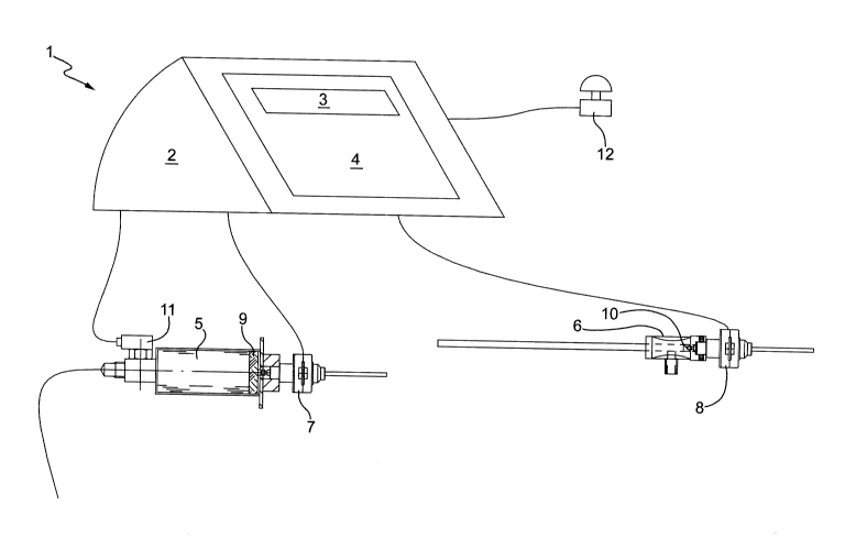
In the figure, number 1 indicates an assembly for
kyphoplasty procedures according to the present invention
as a whole.
The assembly 1 comprises a control unit 2, a display
3, which is connected to the control unit 2 and is suited
to transmit information to the medical personnel, and a
keyboard 4, through which the medical personnel
communicates with the control unit 2, so as to set the
operations to be performed.
The assembly 1 comprises, furthermore, a syringe 5,
which is useful to inflate the balloon (which is not
illustrated for simplicity reasons), and an injector 6,
which is useful to introduce the cement into the vertebral
cavity created. The syringe 5 and the injector 6 are
associated to a respective stepper motor 7 and 8 featuring
an adequate power, which is responsible for the movement of
a respective plunger 9 and 10.
CA 02847073 2014-02-26
WO 2013/035000
PCT/1B2012/054140
4
The motors 7 and 8 are connected to the control unit 2
by means of a wired or wireless connection.
The syringe 5 is associated to a pressure sensor 9, Sc'
as to remotely detect in real time the pressure present
inside the balloon. The pressure sensor 11 is connected to
the control unit 2 by means of a wired or wireless
connection, as well.
Finally, the assembly 1 comprises an emergency stop
button, which is schematically shown in the figure and is
indicated with number 12, to be activated by the medical
personnel in the event that operating faults occur. The
emergency stop button 12 is connected to the control unit 2
by means of a wired or wireless connection, as well.
Both the syringe 5 and the injector 6 comprise limit
stop detecting sensors, which allow a reset to be performed
at the beginning of the operating cycle and, at the same
time, allow the medical personnel to make sure that the
assembly correctly works before using it on the patient.
In use, the doctor, after having duly prepared the
syringe 5 for the inflation of the balloon inside the
channel that has been previously created in the vertebra,
remotely activates the movement of the plunger 9 by
controlling the stepper motor 7 through the control unit 2.
In particular, the keyboard 4 is arranged behind a
protective shield (which is not illustrated for simplicity
CA 02847073 2014-02-26
WO 2013/035000
PCT/1B2012/054140
reasons), so as to protect the doctor from radiations.
The doctor can visually follow the development of the
procure by means of the radiography monitoring system
normally used and, in so doing, can increase or decrease
5 the pressure inside the balloon and check the results in
real time.
The inflation of the balloon can be scheduled and then
activated, or it can be controlled in real time by the
doctor.
The pressure inside the balloon is constantly detected
by the pressure sensor 11 and displayed on the display 3.
To this regard, an inflation stop command can be insert,
which allows the inflation to be stopped when a given
pressure, which has been previously set, is reached.
After the balloon inflation step has ended, the doctor
manually removes the syringe 5. During this step, the
radiography monitoring system is not active and, therefore,
there are no radiations. After having removed the syringe
5, the doctor introduces the injector 6, which is suited to
insert the cement.
At this point, the doctor acts in the same way as he
acted during the inflation step and stands behind the
protective shield. In this way, the doctor remotely
activates the movement of the plunger by controlling the
stepper motor 8 through the control unit 2.
CA 02847073 2014-02-26
WO 2013/035000
PCT/1B2012/054140
6
Also in this case, the insertion of the cement can be
scheduled and then activated, or it can be controlled in
real time by the doctor.
Therefore, the doctor can remotely perform the
insertion of the cement into the cavity by monitoring the
process by means of the radiography monitoring system,
until the cavity is filled.
At this point, the procedure can be considered as
concluded and, after the monitoring system has been
disabled, the doctor can safely remove the entire apparatus
from the patient.
Obviously, all the devices that come into contact with
the patient, such as the syringe, have to be considered as
disposable and, therefore, are thrown away at the end of
the procedure.