Note: Descriptions are shown in the official language in which they were submitted.
CA 02847088 2014-02-26
WO 2013/035117 PCT/1T2012/000081
1
Portable device for financial transactions
The present invention relates to a portable device for financial
transactions which can be used for safe payments and/or withdrawals
of cash in real time and for other forms of credit and/or banking
operations in general.
In the technical sector of electronic economic transactions major efforts
are being constantly made to develop systems of the so-called
electronic wallet type where sums of money are withdrawn from an
account at an approved bank and are used for the payment of goods or
services instead of using cash.
Also known are economic transactions performed using "cashpoint
card" means which require the keying-in of personal codes, as well as
"credit card" means which require confirmation of the owner's
signature and in some cases the presentation of an identity document.
However, these known means may in some way be fraudulently
reproduced or used by users other than the owner, should the said
means be lost or stolen.
Also known are payment systems which use prepaid cards, with the
disadvantage that they require topping up of the sum available
whenever the funds run out and allow payments which are limited by
the very nature of the card.
WO 01/35334 and US 5,623,552 disclose credit cards which envisage
reading of fingerprints for identification of the owner and
authorization for money transfers.
US 2007/0220273 discloses a card for transactions which uses the
input of biometric identification data and a wireless system for
communicating an access code in the vicinity of a reader or a
transaction system.
CA 02847088 2014-02-26
WO 2013/035117
PCT/1T2012/000081
2
WO 2011/065867 discloses known solutions for high-security real-time
economic transactions which use mobile phones.
However, although improvements are being continually made in order
to increase the safety and practical nature of the known systems, with
none of these systems isit, possible to obtain the certainty that the
user is effectively the legitimate owner of the credit means; moreover,
with none of these known systems is it possible to have a single means
or a single device which may be electronic and which simultaneously
perform the functions of credit cards, cashpoint cards and cash.
Moreover, all the known systems which use means of the "badge" type,
such as credit cards or cashpoint cards, are subject to dimensional
requirements stipulated by the ISO 7810 standards such that they
must have a well-defined maximum thickness which results in the
necessary use - for example for the fingerprint recognition means - of
thin mono-dimensional sensors which are less reliable than other types
of sensors which have greater thicknesses and which cannot be used in
these cards. In fact, as mentioned, in order to comply with the
requirements of the ISO standards, the badge means must have a
limited thickness so as to be able to bend or twist along all the axes
without suffering damage.
These known systems therefore have the disadvantage that they
envisage three separate means for the functions which are normally
used in economic transactions, namely credit card, cashpoint card and
cash card.
Moreover, these known means have limitations in terms of their
thickness and are subject to damage, which may occur for example
inside one's pocket or wallet, owing to their limited thickness.
Moreover, the type of recognition sensor of these known means must
have a small thickness so that they can be used with badges means,
with the result that they must be preferably of the mono-dimensional
CA 02847088 2014-02-26
WO 2013/035117
PCT/1T2012/000081
3
type, typically in the form of a single strip which is less reliable and
difficult to read. In the
aforementioned case other types of sensors
with a greater thickness cannot be used.
In fact the known means do not ensure a hi-unique and non-
reproducible correspondence between the legitimate owner of the
credit means and the user thereof during a financial transaction of the
economic type, since both the codes of the cashpoint cards and the
signatures of the credit cards as well as wireless access operations,
such as those described in the publication US 2007/022073, may be
fraudulently intercepted, reproduced and used by non-authorized third
parties.
A further disadvantage of the known devices consists in the
impossibility of transferring sums of money between credit cards or
cashpoint cards.
The object of the present invention is therefore to provide a portable
device which allows an economic transaction to be performed safely in
real time, so as to replace credit cards, cashpoint cards and cash with a
single means, which portable device is able to be perform the detection
of biometric data, such as fingerprints, store said data for subsequent
use and authenticate in a certain manner the validity of each
subsequent transaction request made by the user, confirming that the
person performing the transaction is the legitimate owner of the credit
means authorized for this purpose, the biometric data of said person
being those stored, without having to key in codes or provide
signatures or transmit data remotely and/or substantially without
contact between a known transmitter and a known reader, allowing
bank access directly without the use of codes or PINs.
Another object of the present invention is to perform the wireless
communication between device and reader associated with the POS
terminal preferably in a restricted and/or protected confined space so
that the electromagnetic, optical or similar waves remain within this
CA 02847088 2014-02-26
WO 2013/035117 PCT/1T2012/000081
4
space and are not propagated within the environment.
A further object of the present invention is to provide a portable device
which does not involve additional management costs in the case of use
as cash.
A further object of the present invention is to provide a portable device
which, in the event of loss or theft, cannot be used by third parties
since the biometric data, such as one or more fingerprints, cannot be
recognized.
A further object of the present invention is to provide a portable device
which allows the transfer of sums of money between said portable
devices.
Yet another object of the present invention is to ensure greater
convenience, practicality of use and robustness compared to the known
systems, including also credit cards which envisage recognition by
means of fingerprints. In fact, according to the present invention,
there are no limitations in terms of thickness, as in the case of
conventional badges; consequently there is no risk of damage due to
folding or the like, allowing the use of more sensitive and reliable
sensors.
Another further object of the present invention is that of providing a
device which is directly connected to the bank account and which,
owing to its practical and immediate nature, may also be used to
manage the payment of insignificant sums, such as that required to
buy a coffee, bus ticket or newspaper, without additional costs, also
managing cash in a different manner, since by being able to withdraw
exact sums, the device can be used to make purchases down to a very
small amount, without having to keep in one's pocket loose change
which is often no longer considered or is lost or ignored for use as cash.
CA 02847088 2014-02-26
WO 2013/035117
PCT/1T2012/000081
According to the present invention, the following is provided: a
portable device which comprises essentially a biometric data reader,
preferably any type of data sensor and in particular, for example a
fingerprint sensor of preferably bi-dimensional capacitive, resistive,
optical type or similar, a power supply unit suitable for supplying
electric power to the portable device, clearly co-operating with an
associated recharging system; circuits for reading and storing the
biometric data, preferably for example fingerprints, as well as for
subsequently identifying and validating said data, in order to associate
in a certain manner the portable device according to the invention with
the legitimate owner and allow the subsequent identification,
recognition and validation of the said biometric data of the owner.
The portable device according to the present invention is also
envisaged as being able to communicate wirelessly with a reader
associated with a POS (Point of Sale) terminal of a retail outlet. This
wireless communication is performed preferably in a confined space or
in an extremely restricted and/or protected receiving seat so that the
electromagnetic, optical or similar radiation for communication
between the portable device and the reader associated with the POS
terminal remains within the extremely small confined space and/or the
restricted and protected seat and is not propagated within the
environment, thus avoiding any possible interception and reproduction
thereof.
"Confined space" in this context is understood as meaning a zone
where the electromagnetic waves or the like which convey the signal
between a portable device 100 according to the invention and an
associated reader 110 remain within said confined space. Still in this
connection the "confined space" may consist of both the volume formed
between the surfaces for supporting the portable device 100 according
to the invention and an associated reader 110 according to the
invention and/or any type of suitable reader, and also be in the form of
a surface or in the form of a receiving seat.
CA 02847088 2014-02-26
WO 2013/035117 PCT/1T2012/000081
6
These and other characteristic features of the present invention will
become clear from the detailed description which follows of a non-
limiting example of a preferred embodiment of the portable device
according to the invention with reference to the figures in the
accompanying drawings in which:
Figure 1 shows the block diagram of the portable device according to
the invention;
Figure 2 shows the block diagram of the reader associated with the
PUS terminal and intended to communicate with the portable device
according to the invention;
Figure 3 shows, according to the invention, in a schematic manner
opposite each other a portable device and a corresponding reader;
Figure 4 shows in detail the block diagram of the program for
operation of the microprocessor (MCU); and
Figure 5 shows the flow diagram of an example a transaction which
uses, according to the invention, the portable device in combination
with the corresponding reader associated with the POS.
With reference to Figures 1 and 2 these show the block diagram of a
preferred embodiment of a portable device 100 according to the
invention and an associated reader 110 communicating therewith.
In particular, the portable device 100 comprises a microprocessor unit
or micro controller unit (MCU) 1 to which a biometric reader of any
known type 2, at least one communication module 3 and optionally a
display 4 with associated control circuits 5 are connected. A power
supply battery 6 is also connected to the MCU 1 via a recharging
controller 7 which controls a recharging means 8 of any suitable type,
for example preferably of the inductive or similar type.
An optional additional memory 9 and optional anti-tamper system 10
may also be connected to the MCU 1.
The reader 110 shown in Figure 2 comprises essentially a
communication module 11 designed to communicate with the at least
CA 02847088 2014-02-26
WO 2013/035117
PCT/1T2012/000081
7
one communication module 3 of the portable device 100, an interface
12 preferably of the USB type and designed not to emit waves
externally, associated with a POS terminal. A recharging device 13 of
any suitable type, for example of the inductive type, connected by
means of a power supply module 14 to the electricity mains, also forms
an essential part of the reader 110.
More particularly, the device 100 is contained within a housing which
has a form convenient for being used in a simple and ergonomic
manner with one - either right or left - hand, having dimensions
approximately the same as those, for example, of a cigarette lighter or
an electronic car key.
This housing contains the components shown in the block diagram of
Figure 1 and in particular the MCU 1 which controls the entire
portable device 100 and is activated by the positioning on the surface
of the biometric reader 2 of at least one prechosen finger of the
legitimate user who, exerting a more or less light pressure on the said
surface, closes the circuit of any activation means providing power to
the entire device 100. The activation means may consist, for example,
of a microswitch which is positioned underneath the said biometric
sensor 2 or a capacitive, resistive or proximity sensor which is provided
in any convenient position of the device.
Activation of the device is confirmed by means of displaying of a
suitable message on the display or by means of lighting up of one or
more micro LEDs and/or an acoustic message or a vibration.
More particularly, the biometric reader 2 may be any fingerprint
reader, preferably a sensor of preferably hi-dimensional capacitive,
resistive, optical type or similar.
The biometric sensor 2 reads the fingerprint which is formed on its
surface and informs the MCU 1, which carries out an initial
qualitative evaluation thereof. Once the quality thereof has been
CA 02847088 2014-02-26
WO 2013/035117 PCT/1T2012/000081
8
approved, the MCU 1, via at least one of the device communication
modules 3 connected to any one of the reader communication modules
11 according to Figure 2, is able to receive the information for:
starting the operations for recording one or more fingerprints in
the memory of the MCU 1 and/or in the additional memory 9 of the
device and, once the entire recording operation has been completed,
preventing the addition of and/or variation of the recorded data, if this
reader is situated at the bank, or
checking that the fingerprint itself belongs to the legitimate
user and that it is therefore already recorded in the memory of the
MCU and/or in the additional memory 9, if this reader is connected to
a POS.
The housing of the device also contains a recharging controller 7. This
definition is understood as meaning preferably any means which is
able to monitor periodically the charged state of the battery 6 of the
portable device 100 and, if necessary, request rapid recharging thereof.
The operations described hitherto may be performed if the recharging
controller 7 gives its consent, after checking that the voltage level
present in the battery 6 is sufficient to power the necessary
components of Figure 1 for positive completion of the required
operation. If this is not so, the recharging controller 7 signals the need
for recharging and/or requests activation of a recharging means 8 for
example preferably of the inductive type.
Protection of the integrity and accuracy of the biometric information
contained in the memory of the MCU 1 and/or in any additional
memory 9 (information which in the example of embodiment of the
present invention consists for example of one or more fingerprints, i.e.
up to ten fingerprints) is ensured by one or more anti-tamper systems
which, in the case of an attempt to perform forced opening of the
portable device 100, instantaneously render the latter illegible and
unusable.
CA 02847088 2014-02-26
WO 2013/035117 PCT/1T2012/000081
9
A non-limiting example of the anti-tamper system 10 may envisage
means able to send all the remaining voltage of the battery 6 to the
terminals of the memory circuit of the MCU 1 and the additional
memory 9, causing the immediate destruction thereof.
Clearly, it is possible to envisage a battery, for example of the lithium
type, dedicated solely for the anti-tamper system 10 alone and never
used for other purposes.
Alternatively, it is possible to envisage mechanical predefined-
breakage means or chemical means such as phials containing a
suitable corrosive substance.
The portable device according to the present invention may also
envisage that one or more of the recorded fingerprints is used by the
system to emit a silent alarm signal which the circuit concerned will
use in a suitable manner, indicating forced or anomalous operation of
the device.
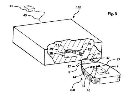
Figures 1, 2 and in particular Figure 3 show a preferred example of
embodiment of the assembly consisting of the portable device 100 and
the corresponding reader 110 to which it is to be connected. The
mutual physical contact between the device (100) and the reader (110)
is maintained by at least one magnetic means (37, 39) associated with
either one of the device 100 or the reader 110 and interacting with a
complementary engaging element (39, 37) provided on the reader 110
or on the portable device 100.
In an alternative embodiment not shown, the mutual contact between
the device 100 and a corresponding reader of any type is obtained by
simply by bringing into contact with the portable device 100 the
surface of the restricted confined space of the reader associated with
the POS.
CA 02847088 2014-02-26
WO 2013/035117
PCT/1T2012/000081
Even more particularly, in the embodiment shown, the portable device
100 has a front end 36 provided with at least one magnetic means 37
preferably consisting of at least one pair of magnets 37, while the
reader 110 has a receiving seat 38 which has internally at least one
complementary magnetic engaging element 39 preferably consisting of
at least one pair of magnets 39. When the front end 36 of the portable
device 100 is inserted inside the receiving seat 38 of the reader 110,
the magnets 37 and 39 respectively provided, as said, on the end 36 of
the portable device 100 and inside the receiving seat 38 of the reader
110 in corresponding positions firmly keep the portable device 100 in
contact with the reader 110 so that the respective device
communication module 3 and reader communication module 11 remain
in close physical contact and may exchange data without emitting
waves of any type externally.
The symmetrical form of the device 100 could give rise to incorrect
positioning of the said device inside the reader 110, for example, in the
case where an optional communication unit for reception/transmission
(RX TX) between the two elements, i.e. device and reader, is concerned.
In fact, in order to comply with the need to maintain within an
extremely confined space the exchange of information, the device 110
on the RX side must be placed in physical contact with the device 100
on the TX side, and vice versa. This result is obtained by providing in a
suitable position within the receiving seat 38 of the reader 110 two
magnets 39 which have facing polarities so as to come into contact
with two similar magnets 37 arranged on the surface of the front end
36 of the device 100. The polarities of the magnets will ensure that
correct positioning of the device 100 inside the reader 110 corresponds
to secure locking together of the two elements, while incorrect
positioning of the device 100 inside the reader 110 produces expulsion
of the device from the reader owing to the magnetic repulsion effect.
Clearly, if the magnetic means 39 of the reader 110 are composed of
electromagnets, the force of the latter may be adjusted so as to be
maximum during use and practically zero at the end of the operations,
CA 02847088 2014-02-26
WO 2013/035117
PCT/1T2012/000081
11
for easy extraction of the device from the receiving seat 38.
Preferably, as shown in Figure 3, for the sake of convenience of use the
arrangement of the parts which form the device 100 and the
corresponding reader 110 is such as to allow horizontal insertion of the
device 100 inside the reader 110.
A different arrangement (not shown) of the parts may also be
envisaged where the two elements, device 100 and reader 110, are
arranged vertically; in this case, for example, the magnetic means 39
of the reader 110 interact with a complementary engaging element 37
made of ferromagnetic material arranged on the portable device 100,
or vice versa, so as to allow the possibility of use with either the right
hand or left hand, as required.
In the case where there is also a radiofrequency communications
system, the latter may function preferably when the device 100 and
the reader 110 are positioned in contact with one another, so that the
confined space with separates them is close to zero and no
electromagnetic radiation or the like may be emitted for ranges of
more than one millimetre of distance or less. The correct positioning of
the device 100 in contact with the surface of the reader or inside the
receiving seat of the reader 110 and the correct recognition of the
fingerprint are preferably signalled by suitable switching-on of at least
one LED provided for this purpose, as will be explained more clearly
hereinbelow.
The portable device 100 is provided, for example, with LEDs 44, 45, 46
and 47 which have specific functions and meanings:
the LED 44 indicates correct insertion or positioning of the
device 100 inside, or in contact with, the reader 110 and, where
appropriate, locking of the magnets 37, 39;
the LED 45 indicates that the fingerprint has been correctly
stored;
CA 02847088 2014-02-26
WO 2013/035117
PCT/1T2012/000081
12
the LED 46 indicates that the fingerprint has been recognized as
valid and as therefore belonging to the legitimate user;
the LED 47 indicates that an error condition has occurred: the
fingerprint is not recordable or has not been recognized as belonging to
the correct user.
The reader 110, via the interface 12, preferably of the USB type and
such as not to emit waves externally, associated electric cable 40 and
connector 41, receives from the PUS terminal or from the bank
registration terminal suitable instructions as to what the device 100
must do:
perform payment when required by the sales point;
analyze the fingerprint detected on the biometric reader 2; and
record it in the memories of the MCU 1 and additional memory
9 of the same device 100.
The alerting of the user as to correct or incorrect positioning or
operation may be associated with operation of LEDs and/or acoustic
signals and/or vibrations which are known per se.
During this stage of the operations the reader 110 and the device 100
also keep, where required, the recharging inductors 13 and 8,
respectively, in close contact with each other so that a correct power
supply may be provided via them to the device 100 in the case where
recharging of the device 100 is not sufficient to perform the required
operations.
- Figure 4 shows in particular the operating program of the MCU 1
which comprises an operations control motor 30, which implements the
logic functions for managing the biometric reader 31. The operations
control motor 30 also implements the I/0 logic functions for managing
the battery 32. Furthermore the operations control motor 30 manages
the communication protocol 33 with the reader 110, preferably via an
encrypting routine 34.
CA 02847088 2014-02-26
WO 2013/035117 PCT/1T2012/000081
13
The operations control motor 30 deals, finally, with the I/O of the anti-
tamper system 35, where present.
More particularly, Figure 4 shows the functions which are performed
inside the MCU 1 under its direct control.
In particular, the operations control motor 30 cyclically monitors the
channels for communication from and to:
the routine 34 for encrypting the communication protocol 33;
checks for any notifications from the anti-tamper system 35;
the routine 31 for management of the biometric reader 2;
checks the I/O signals of the controller of the battery 32.
Considering the time sequence of the operations, the latter are
performed as follows:
activation of the device generated by introduction of the same
inside the reader or in contact therewith;
communication by the reader to the operations control motor
30, via the communication protocol 33 and the encrypting routine 34,
of the operations which are to be performed;
reading of the fingerprint or the fingerprints via the routine 31
for management of the biometric reader 2;
storage of the fingerprint or fingerprints (if at the bank for
authorization of the device user);
recognition of the fingerprint or fingerprints for enabling
execution of a financial operation;
in the I/O time delays of any one of the channels connected to
the operations control motor 30, the control motor itself interrogates
the routine for managing the battery 32 and/or the routine for
managing the anti-tamper system 35.
Figure 5 shows the flow diagram of a standard example of a financial
transaction comprising the steps of:
50 introduction of the amount on the POS
51 reception of request from the POS
CA 02847088 2014-02-26
WO 2013/035117
PCT/1T2012/000081
14
52 request for convalidation of the fingerprint
53 verification by the biometric reader control unit 31 that the
fingerprint belongs to the legitimate owner of the portable device 100
54 termination of the operation if the fingerprint is not
convalidated by the verification function 53
55 sending of confirmation to the POS if the fingerprint is
convalidated
56 request from the POS to the payment bank
57 response of the bank to the POS
58 verification of the financial availability
59 if affirmative, sending of OK signal to portable device 100
60 recording of the operation
61 if negative, sending of reject signal to portable device 100
62 end of operation.
More particularly, the situation shown in the flow diagram according
to Figure 5 may refer to an operation for the purchase of goods or
services to be performed at an agreed trading establishment via a bank
which has adopted the system for use of the portable device 100.
Therefore, the operation (step 50) for introduction of the amount to be
paid to the POS terminal occurs as the conclusion of the sales
operation. At this point, the POS terminal asks the purchaser to insert
the portable device 100 into the associated reading unit 110.
Thereafter, the request (step 51) for payment by the POS terminal is
received from the MCU 1 which requests in turn (step 52), for example
via lighting up of a signalling LED, that the owner of the device 100
should allow verification, on the biometric reader 2, of one of his/her
fingerprints previously recorded at the bank.
There are two possible outcomes for this verification operation (step
53):
the verification proves to be negative, resulting in termination of
the operation (step 54)
CA 02847088 2014-02-26
WO 2013/035117
PCT/1T2012/000081
the verification proves to be positive, resulting in sending of
confirmation (step 55) that the owner's identity is valid
All this allows the POS terminal to send to the bank the request for
availability of the sum relating to the sales operation in progress (step
56). In step 57, as well step 58, the response as to financial
availability is provided by the bank to the POS terminal, namely,
either:
negative (step 61), resulting directly in the end of the operation
(step 62) or
positive (step 59), resulting in regular registration of the
accounting operation and successful completion of the sales operation
(step 60).
As regards that stated above, a preferred embodiment of the invention
has been described, without however limiting it in any way to the
characteristic features described. The persons skilled in the art will
understand that, in the light of that made known here, modifications
and numerous changes may be made without departing from the scope
of the present invention as defined in the accompanying claims.