Note: Descriptions are shown in the official language in which they were submitted.
*-^ CA 02847148 2014-02-27
A
DESCRIPTION
CATHETER BALLOON AND BALLOON CATHETER
Technical Field
[0001] The present invention relates to a catheter
balloon and a balloon catheter.
Particularly, the present invention relates to a
balloon and a balloon catheter inserted into lumens in
the body.
Background Art
[0002] A catheter equipped with a balloon (balloon
catheter) is used for body organ dilation, which is
performed for maintaining a luminal space by means of
placing a stent in a stenosed site of lumens in the
body, such as blood vessels, the bile duct, the
esophagus, the trachea, the urethra, and other organs.
Moreover, the catheter is also being used for treating
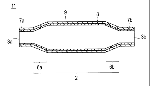
ischemic heart diseases or for urethral catheterization
for patients having a difficulty in urination.
[0003] Accordingly, the balloon catheter is required
to have properties including (1) trackability (a
property that enables the balloon to move along the
tortuous blood vessels and the like), (2) an ability to
pass through stenosed sites of blood vessels and the
¨1¨
,.
CA 02847148 2014-02-27
%
like, (3) an ability to dilate stenosed sites of
calcified blood vessels and the like, (4) compliance
(an appropriate degree of non-extensibility by which
the balloon catheter does not inflate any further once
it has dilated up to a desired diameter), (5) a
sufficient degree of strength and pressure resistance
that enables the balloon catheter to endure the
internal pressure or impact caused at the time of
balloon dilation, and the like.
[0004]
Particularly, the balloon portion is required
to have compliance, pressure resistance, and
flexibility and to be formed of a thin membrane. As
materials of the catheter balloon satisfying such
properties, polyethylene terephthalate, polyolefins,
polyamide, and the like have been conventionally used.
For example, the conventional balloon, which is
obtained as disclosed in JP-A-2008-253786 by means of
selecting aliphatic-aromatic polyamide as a base
polymer and making the aliphatic polyamide having a
short carbon chain into a polymer alloy to improve
compliance or pressure resistance, has aromatic rings
in the main chain, and hence the pressure resistance
and compliance thereof can be improved. However, this
balloon is inferior to a balloon made of polyethylene
terephthalate (PET) and the flexibility thereof is
poorer than that of aliphatic polyamide.
¨2¨
CA 02847148 2016-09-02
For this reason, the JP-A-2008-253786 discloses a
technique relating to a balloon obtained by adding
inorganic crystals to the polymer.
[0005] Moreover, as another technique of improving
pressure resistance and flexibility, JP-A-2005-319289
can be exemplified.
The JP-A-2005-319289 discloses a technique of producing
a balloon by means of biaxial stretch blow molding by
using a block polymer, which includes a polyamide-based
hard segment and a glycol-based soft segment, as a
material of the balloon membrane such that a calculated
elastic modulus under a pressure caused at the time of
balloon dilation becomes 1,300 MPa or higher.
[0006] If inorganic crystals are added to the
polymer as described in the JP-A-2008-253786, pressure
resistance or compliance of the balloon are definitely
improved. However, the improvement in the flexibility
or a property of thin membrane cannot be expected.
Moreover, the catheter balloon repeatedly dilates and
contracts by medical practice. In the balloon which is
disclosed in the JP-A-2008-253786 and formed of a
membrane that is merely a mixture of inorganic crystals
and a polymer, the adhesion force between the polymer
and the inorganic crystals is weak, and the inorganic
crystals themselves do not easily dilate or contract.
Consequently, when the balloon dilates, delamination
occurs in the interface between the polymer and the
¨3¨
CA 02847148 2016-09-02
A *
inorganic crystal inside the membrane, and gaps are
formed.
These gaps act as cracks in the entire membrane as a
mixture of the inorganic crystals and the polymer,
hence rupture of the balloon membrane may start from
the gaps.
Particularly, the balloon is generally in the form of a
cylinder and has a structure that dilates due to the
internal pressure thereof. Therefore, from a dynamic
viewpoint, a maximum stress is applied to the innermost
circumference thereof, and this leads to a problem that
balloon membrane easily ruptures from the direction of
the inner circumference if there are gap inside the
membrane.
[0007] Furthermore, through the biaxial stretch blow
molding that is performed as described in the JP-A-
2005-319289 by using the block copolymer, which
includes a polyamide-based hard segment and a glycol-
based soft segment, as a material of the balloon
membrane, sufficient pressure resistance is not
obtained.
Particularly, as described above, from a dynamic
viewpoint, a maximum stress is applied to the innermost
circumference of the balloon, hence the problem that
the balloon membrane easily ruptures from the direction
of the inner circumference thereof cannot be resolved.
SUMMARY OF INVENTION
[0008] In order to intend to achieve its objects,
¨4¨
CA 02847148 2016-09-02
the present inventors according to a broad aspect
thereof found that the above problems can be sought to
be solved by a cylindrical catheter balloon formed of a
membrane as a laminate of at least two or more layers
including a polyamide elastomer layer and a polyamide
layer, in which the polyamide elastomer layer is
disposed at the inner side of the polyamide layer, a
refractive index nr1 in the circumferential direction of
a cross-section perpendicular to the axis in the
surface of inner side of the polyamide layer is greater
than a refractive index nr2 in the circumferential
direction of a cross-section perpendicular to the axis
in the surface of inner side of the polyamide elastomer
layer, and a difference between the refractive index nri
and the refractive index nr2 is 0.01 or greater.
[0009] In
order to intend to solve the above problem,
embodiments of the present invention are focused on the
orientation of polymers in the balloon membrane, and
aim to provide a catheter balloon with improved
pressure resistance of the entire membrane and a
balloon catheter by converting the maximum stress
applied to the innermost circumference into
extensibility.
[0010] If
the following description and illustrative
embodiments illustrated in the attached drawings are
taken into consideration, other intended objects,
properties, and characteristics of the present
invention will be revealed.
¨5¨
CA 02847148 2016-09-02
Brief Description of Drawings
[0011]
[Fig. 1A] Fig. lA is a schematic view showing
an example of a catheter balloon according to
embodiments of the present invention.
[Fig. 1B] Fig. 1B is a schematic view showing another
example of the catheter balloon according to embodiments
of the present invention.
[Fig. 2] Fig. 2 is a schematic view for illustrating a
mold for molding the catheter balloon according to
embodiments of the present invention.
[Fig. 3] Fig. 3 is a schematic view showing an example
of a balloon catheter according to embodiments of the
present invention.
[Fig. 4] Fig. 4 is a view illustrating examples and
showing experimental data of embodiments of the present
invention.
[Fig. 5] Fig. 5 is a view showing experimental data of
examples of embodiments of the present invention.
[Fig. 6] Fig. 6 is a view showing experimental data of
examples of embodiments of the present invention.
[Fig. 7] Fig. 7 is a view showing experimental data of
examples of embodiments of the present invention.
[Fig. 8] Fig. 8 is a view showing experimental data of
examples of embodiments of the present invention.
¨6¨
CA 02847148 2016-09-02
=
Description of Embodiments
[0012] Hereinafter, embodiments of the present
invention will be described in detail.
[0013] In addition, the present application is based
on Japanese Patent Application No. 2011-0214496 filed
September 29, 2011.
[0014] A first aspect of embodiments of the present
invention is a cylindrical catheter balloon formed of a
membrane as a laminate of at least two or more layers
including a polyamide elastomer layer and a polyamide
layer, in which the polyamide elastomer layer is
disposed at the inner side of the polyamide layer, a
refractive index nri in the circumferential direction of
a cross-section perpendicular to the axis in the
surface of inner side of the polyamide layer is greater
than a refractive index nr2 in the circumferential
direction of a cross-section perpendicular to the axis
in the surface of inner side of the polyamide elastomer
layer, and a difference between the refractive index nri
and the refractive index nr2 is 0.01 or greater.
[0015] According to the above aspect, a catheter
balloon that has been further improved in terms of
pressure resistance compared to the conventional
catheter balloon can be provided.
Moreover, it is possible to inhibit the balloon portion
from dilating due to pressurization while maintaining
¨7¨
CA 02847148 2016-09-02
=
flexibility and pass-through ability that the
conventional balloon has. Furthermore, it is possible
to reliably dilate a lesion and to prevent the mucous
membrane or the inner lining of blood vessels from
being damaged.
Accordingly, if the balloon according to embodiments of
the present invention is used, it is possible to obtain a
balloon catheter which exhibits excellent trackability at
the time of the balloon dilation, inhibits cracking or
crazing as a starting point of rupture, and has excellent
mechanical strength and flexibility.
[0016] In addition, a compliance, which shows how
easily the diameter can be increased, of the balloon of
embodiments of the present invention is as low as 0.012
mm/atm or less. Therefore, it is possible to dramatically
inhibit the balloon portion from stretching due to the
pressurization while maintaining flexibility and pass-
through ability that the conventional balloon has.
[0017] The structure of the catheter balloon
according to embodiments of the present invention will
be described first by using drawings, and then the
properties and each constituent of the balloon will be
described below. However, each of Figs. 1A and 13 is
merely an example of the catheter balloon, and the
scope of the present invention is not limited thereto.
[0018] Fig lA is a cross-sectional view showing an
example of the catheter balloon according to embodiments
of the present invention that has a two-layer structure
¨8¨
CA 02847148 2016-09-02
consisting of a polyamide layer and a polyamide elastomer
layer. Fig. 1B is a cross-sectional view showing an
example of the catheter balloon of embodiments of the
present invention that has a three-layer structure in
which a polyamide elastomer layer 8, a polyamide layer 9,
and the polyamide elastomer layer 8 are laminated on each
other in this order.
[0019] It is illustrative for a catheter balloon 11
according to the present invention to be constituted
with a cylindrical membranous body 2 that can dilate or
contract by fluid supplied from a catheter and
connection portions 7a and 7b that extend from both
ends in the axial direction of the membranous body and
are connected to the catheter.
In the respective connection portions 7a and 7b at both
ends, opening portions 3a and 3b through which a
catheter is inserted are formed.
It is illustrative for the opening portion 3b of one of
the connection portions to have a diameter larger than
that of the opening portion 3a of the other connection
portion.
Moreover, the catheter balloon 11 has a cylindrical
portion which is for dilating stenosed portions of
lumens in the body, such as blood vessels, the ureter,
and the bile duct, and has a practically uniform outer
diameter.
¨9¨
CA 02847148 2016-09-02
[0020] As shown in Figs. 1A and 1B, each of both
ends of the cylindrical membranous body 2 may have a
tapered shape (portion with a gradient).
That is, it is illustrative for the balloon according
to embodiments of the present invention to have the
cylindrical membranous body 2 including tapered
portions 6a and 6b that have the shape of an
(approximately) truncated cone (or the shape of an
approximately truncated pyramid) becoming narrow toward
the both ends thereof, and the connection portions 7a
and 7b that are linked respectively to the tapered
portions 6a and 6b and are connected to the catheter
extending out of the axial direction.
Further, in the connection portions 7a and 7b at the
both ends, opening portions 3a and 3b through which the
catheter is inserted are respectively formed.
[0021] When both ends of the cylindrical membranous
body have a tapered shape, the portion where the
diameter of the balloon is maximized continues in the
central portion of the cylindrical membranous body.
Moreover, the tapered portions 6a and 6b continue from
the central portion of the cylindrical membranous body
and show the change in which the diameter continuously
decreases toward the end thereof.
[0022] The connection portions 7a and 7b connected
to the catheter continue respectively from the tapered
portions 6a and 6b, and have small outer diameters of
almost the same size. A balloon is mounted on the
¨10¨
CA 02847148 2016-09-02
catheter in the connection potions 7a and 7b, and the
opening portions 3a and 3b are formed respectively in
these portions.
In addition, the tapered portions 6a and 6b and the
connection portions 7a and 7b connected with the catheter
are respectively positioned in both ends of the
cylindrical membranous body of the balloon. The shapes
of the respective tapered portions and connections
portions may be different from each other.
[0023] The catheter balloon according to embodiments
of the present invention is formed of a membrane having
a multi-layer structure as a laminate of at least two or
more layers including a polyamide elastomer layer and a
polyamide layer. The catheter balloon is illustratively
formed of a membrane having one to three polyamide
elastomer layers and one to two polyamide layers, and
more illustratively formed of a membrane having two
polyamide elastomer layers and one polyamide layer.
[0024] If the polyamide elastomer is laminated on
the polyamide as described above, a parison, which will
be described later, can be easily molded by coextrusion.
Moreover, flexibility and pass-through ability required
for a catheter balloon as well as pressure resistance
can be established simultaneously.
[0025] Regarding the order of laminating the
polyamide elastomer layer 8 and the polyamide layer 9,
as long as a laminate structure, in which the polyamide
elastomer layer 8 is disposed at the innermost side and
¨1 1¨
CA 02847148 2016-09-02
the polyamide layer 9 is laminated on the outer surface
of the polyamide elastomer layer 8, is established,
other layers may be laminated in any order without
particular limitation.
[0026] It is particularly illustrative for the catheter
balloon according to embodiments of the present invention
to be constituted with a membrane having a three-layer
structure in which the polyamide elastomer layer 8, the
polyamide layer 9, and the polyamide elastomer layer 8 are
laminated on each other in this order.
[0027] If the polyamide elastomer layer is formed as
an outermost layer, the balloon exhibits flexibility
when being inserted into the body by being mounted on a
catheter. Accordingly, the balloon excellently passes
through lumens in the body, such as blood vessels.
[0028] Moreover, the surface of the polyamide
elastomer layer provided as an outermost layer or the
polyamide layer may be optionally coated with a
biocompatible material or an antithrombotic material.
As the biocompatible material or the antithrombotic
material, one kind among various known polymers may be
used alone, or a mixture thereof may be used. For
example, natural polymers (collagen, gelatin, chitin,
chitosan, cellulose, polyaspartic acid, polyglutamic
acid, polylysine, casein, and the like), synthetic
polymers (phosphatide polymers and Methacryloyloxyethyl
Phosphorylcholin (MPC) block polymers having a
phosphoric acid group on the side chain thereof),
¨12¨
CA 02847148 2016-09-02
'
= '
. .
polyhydroxyethyl methacrylate, hydroxyethyl
methacrylate-styrene copolymers (for example, a HEMA-
St-HEMA block copolymer), polymethyl methacrylate,
polylactic acid, polyglycolic acid, a lactic acid-
glycolic acid copolymer, polyethylene, polypropylene,
and the like can be illustratively used.
[0029] In order to make it easy to insert the
catheter balloon according to embodiments of the present
invention into blood vessels or a guide catheter, it is
illustrative to treat the outer surface of the balloon or
the membranous body such that the outer surface of the
balloon or the membranous body exhibits lubricity when
coming into contact with blood and the like.
Examples of the above treatment include a method of
coating the surface with hydrophilic polymers such as
poly(2-hydroxyethylmethacrylate), polyhydroxyethyl
acrylate, hydroxypropyl cellulose, methyl vinyl ether-
maleic anhydride copolymers, polyethylene glycol,
polyacrylamide, polyvinyl pyrrolidone, and random or
block copolymers of dimethylacrylamide-glycidyl
methacrylate, a method fixing these polymers onto the
surface, and the like.
[0030] It is illustrative for the polyamide
elastomer layer to be formed while being in close
contact with the surface of the polyamide layer.
Furthermore, it is illustrative for the polyamide
elastomer layer to be formed while being in close
contact with the entire surface of the polyamide layer.
¨13¨
CA 02847148 2016-09-02
=
In this manner, a catheter balloon with improved
pressure resistance can be provided.
[0031] As described above, the catheter balloon
according to embodiments of the present invention is a
cylindrical membranous body in which a polyamide
elastomer layer is disposed at the inner side of a
polyamide layer, in which a refractive index nr1 in the
circumferential direction of a cross-section
perpendicular to the axis in the surface of inner side
of the polyamide layer is greater than a refractive
index nr2 in the circumferential direction of a cross-
section perpendicular to the axis in the surface of
inner side of the polyamide elastomer layer, and a
difference between the refractive index nr1 and the
refractive index nr2 is 0.01 or greater.
The difference between the refractive index nri in the
circumferential direction of a cross-section
perpendicular to the axis in the surface of inner side
of the polyamide layer and the refractive index nr2 in
the circumferential direction of a cross-section
perpendicular to the axis in the surface of inner side
of the polyamide elastomer layer is illustratively from
0.01 to 0.02 and more illustratively from 0.01 to 0.015.
[0032] As described above, if the polyamide
elastomer layer is disposed at the inner side of the
polyamide layer, and the difference between the
refractive index nri in the circumferential direction of
a cross-section perpendicular to the axis in the
¨14¨
CA 02847148 2016-09-02
surface of inner side of the polyamide layer and the
refractive index nr2 in the circumferential direction of
a cross-section perpendicular to the axis in the surface
of inner side of the polyamide elastomer layer is 0.01
or greater, the number of the polyamide elastomer
molecules in the polyamide elastomer layer that are
oriented in the circumferential direction becomes
relatively small. Consequently, the polyamide elastomer
layer obtains a margin for stretching.
It is considered that for this reason, the stress
applied to the innermost circumference can be converted
into extensibility of the polyamide elastomer layer.
[0033] To described in more detail, it is known that
in the system in which internal pressure is applied to a
cylindrical substance such as a catheter balloon,
theoretically, a maximum stress is applied to the
innermost circumference of the cross-section
perpendicular to the axis of the cylindrical substance,
and the stress decreases toward the radial direction of
the cross-section perpendicular to the axis (cylinder
model). Actually, it has been confirmed that when
internal pressure is applied to the catheter balloon,
rupture of the balloon starts from the side of the
innermost circumference in many cases.
In embodiments of the present invention, a flexible polyamide
elastomer layer, in which a relatively small number of
polymers are oriented in the circumferential direction,
is disposed at the side of the innermost circumference
¨15¨
CA 02847148 2016-09-02
to which a maximum stress is applied, whereby the maximum
stress applied to the innermost circumference is converted
into extensibility of the flexible polyamide elastomer layer.
It is considered that for this reason, the internal pressure
applied to the balloon can be effectively absorbed in the
system of the catheter balloon.
[0034] On the other hand, it is considered that since
a hard polyamide layer, in which the number of polymers
oriented in the circumferential direction is relatively
larger than that of the flexible polyamide elastomer
layer, is disposed at the outside of the polyamide
elastomer layer, the strength of the entire catheter
balloon can be maintained.
Moreover, in the balloon membrane according to
embodiments of the present invention, a large number of
polymer chains are crystallized in the hard polyamide
layer in which a relatively large number of polymers are
oriented in the circumferential direction. Accordingly,
an effect that results in excellent compliance is also
obtained.
[0035] From the above facts, it is considered that by
controlling the orientation state of polymer chains in
each layer of the membrane as a laminate of at least two
layers including a polyamide layer and a polyamide
elastomer layer constituting the balloon catheter, the
pressure resistance that makes the rupture starting from
the inner side occur less compared to the conventional
catheter balloon is improved.
¨16¨
CA 02847148 2016-09-02
[0036] The orientation state of the polymer chains
can be confirmed by measuring birefringence in general.
For example, in a uniaxially stretched polymer film, the
molecular chains are oriented in the stretch direction.
Accordingly, there is a difference between a refractive
index in the stretch direction and a refractive index in
a direction perpendicular to the stretch direction.
This results in anisotropy of the refractive index of
light, and can be measured as birefringence.
As methods of measuring birefringence described above,
there are (1) an intensity method, (2) a compensation
method, (3) observation of polarization color, and the
like.
In embodiments of the present invention, birefringence
is measured by the (2) compensation method as follows,
and then a refractive index (nr) in the circumferential
direction of a cross-section perpendicular to the axis
of the balloon, a refractive index (n1) in the long axis
direction of the balloon, and a refractive index (nd) in
a radial direction of the cross-section perpendicular to
the axis of the balloon are calculated.
[0037] A relative refractive index used in
embodiments of the present invention is calculated by
three-dimensional analysis by using a polarization
microscope.
The cross-section of a fragment having a thickness of 16
1.1m that is sliced from the central portion of the
straight tube portion of the balloon and the cross-
-17¨
CA 02847148 2015-10-19
section of a fragment that is sliced in the long axis
direction were observed with a polarization microscope,
and retardation thereof was measured using a
compensator to calculate a birefringence An of the
cross-section and a birefringence An of the long axis
by the following Formulae (1) to (3).
[0038] [Math. 1]
Formula (1)
Lin = R t
Formula (2)
R =Cxf (i)
Formula (3)
f (i) = sin2 + 0.2041 X sin2 i + 0.0627 x sin4
[0039] (In the Formulae (1) to (3), 9R indicates
retardation (nm), t indicates the thickness (16 ( m))
of a sample, C indicates a constant of 0.822 x 10⁴ that
depends on the thickness of a crystal mounted on the
compensator, and i indicates a correction angle
(Radian) of the compensator.)
Subsequently, the birefringence An of the cross-section
and the birefringence An of the long axis calculated by
the Formulae (1) to (3) are assigned to the following
Equations (1) to (3) to calculate solutions of a
refractive index (n,) in the circumferential direction
¨18¨
CA 02847148 2014-02-27
of the cross-section perpendicular to the axis, a
refractive index (nL) in the long-axis direction, and a
refractive index (nd) in the radial direction
(thickness direction) of the cross-section
perpendicular to the axis respectively.
[0040] [Math. 2]
¨19¨
CA 02847148 2014-02-27
Equation (1):
An(Cross-section ) = In, ¨ ndl
Equation (2):
An( Long axis) = inL ¨ nd I
Equation (3):
\
nµ = (n, + + nd 2 ) + 3
Solution:
nr = (¨b NIV---71-77c) 6
= nd An(Long axis)
nd = nr An(Cross-section)
b = 2An(Long axis) ¨ 46n(Cross-section)
2
C = 2 (An(Cross-section)) + V1n(Long axis))2
¨ 2An(Cross-section) x An(Long axis) ¨ 3n2
[ 0 0411 (In the Equations (1) to (3) and solutions,
An (cross-section) indicates a birefringence in the
¨2 O¨
- CA 02847148 2014-02-27
%
slicing direction, An (long axis) indicates a
birefringence in the long-axis direction, nr indicates
a refractive index in the circumferential direction, ni,
indicates a refractive index in the long-axis direction,
nd indicates a refractive index in the thickness
direction, and n is 1.51 (average refractive index.))
In this manner, as described in the experimental
results which will be shown later in examples, it is
possible to calculate the refractive index (nr) in the
circumferential direction of the cross-section
perpendicular to the axis, the refractive index (nL) in
the long-axis direction, and the refractive index (nd)
in the radial direction of the cross-section
perpendicular to the axis in any position in each layer
of the catheter balloon having the multi-layer
structure, by means of the above measurement method
using a polarization microscope.
[0042] Moreover, by calculating the refractive index
(nr) in the circumferential direction of the cross-
section perpendicular to the axis, the refractive index
(nL) in the long-axis direction, and the refractive
index (nd) in the radial direction of the cross-section
perpendicular to the axis by means of the above method,
the orientation state of polymer chains in each
direction can be specified.
For example, the larger the value of nr is, the more
the polymer chains are likely to be oriented in the
circumferential direction, and the larger the value of
¨21¨
CA 02847148 2016-09-02
=
is, the more the polymer chains are likely to be
oriented in the long-axis direction. Furthermore, the
smaller the value of nd is, the more the polymer chains
are likely to exhibit plane orientation, and if nr and
have the same value, the polymer chains may be oriented
in an isotropic state.
In embodiments of the present invention, nr2 of the
polyamide elastomer layer is smaller than nri of the
polyamide layer by 0.01 or a larger value. Accordingly,
in the polyamide elastomer layer, the degree of
orientation in the circumferential direction is low,
hence the innermost circumference of the balloon obtains
a margin for stretching.
[0043] In the present specification, regarding each
of the refractive indices of the surface of inner side
of the polyamide elastomer layer that is disposed at
the innermost side of the balloon, a refractive index
in the circumferential direction of the cross-section
perpendicular to the axis is denoted as nr2, a
refractive index in the long-axis direction is denoted
as n1,2, and a refractive index in the radial direction
of the cross-section perpendicular to the axis is
denoted as nd2. Moreover, regarding each of the
refractive indices of the surface of inner side of the
polyamide layer that is laminated on the surface of the
polyamide elastomer layer, a refractive index in the
circumferential direction of the cross-section
perpendicular to the axis is denoted as nri, a
¨22¨
CA 02847148 2014-02-27
. .
refractive index in the long-axis direction is denoted
as nLi, and a refractive index in the radial direction
of the cross-section perpendicular to the axis is
denoted as nal.
[0044] Herein, each of the refractive indices of the
surface of inner side of the polyamide layer refers to
a refractive index in the area of the polyamide layer
near the inner surface (interface between the polyamide
layer and the polyamide elastomer layer) of the
polyamide layer. For example, the refractive index in
the circumferential direction of the cross-section
perpendicular to the axis of the surface of inner side
of the polyamide layer refers to a refractive index in
the circumferential direction that is found in an area
which starts from the inner surface of the polyamide
layer and is equal to or smaller than one third of the
thickness of the entire polyamide layer.
[0045] Furthermore, herein, each of the refractive
indices of the surface of inner side of the polyamide
elastomer layer refers to a refractive index in the
area of the polyamide elastomer layer near the inner
surface of the polyamide elastomer layer. For example,
the refractive index in the circumferential direction
of the cross-section perpendicular to the axis of the
surface of inner side of the polyamide elastomer layer
refers to a refractive index in the circumferential
direction that is found in an area which starts from
the inner surface of the polyamide elastomer layer and
¨23¨
CA 02847148 2016-09-02
is equal to smaller than a half the thickness of the
entire polyamide elastomer layer.
[0046] Regarding the size of the catheter balloon
according to embodiments of the present invention, the
outer diameter of the cylindrical membranous body is
illustratively 1 mm to 35 mm and illustratively 1.5 mm
to 30 mm when the balloon dilates. Moreover, the length
of the cylindrical membranous body in the long-axis
direction is 3 mm to 80 mm and illustratively 10 mm to
75 mm, and the full length of the balloon (total length
of the cylindrical membranous body and the connection
portions in the long-axis direction) is 5 mm to 120 mm
and illustratively 15 mm to 100 mm.
[0047] The shape of the cross-section perpendicular to
the axis of the balloon according to embodiments of the
present invention is not particularly limited and may be a
circle, an ellipse, an approximately elliptic shape, an
approximately circular shape, or a polygonal columnar shape.
It is illustrative for the balloon according to embodiments
of the present invention to have a cylindrical shape.
[0048] When the catheter balloon according to
embodiments of the present invention contracts, the
average thickness (thickness) thereof is illustratively
m to 50 m and more illustratively 10 m to 30 m.
[0049] If the average thickness of the catheter
balloon is within a range of 5 m to 50 m at the time of
contraction, this is illustrative in view of
¨24¨
CA 02847148 2016-09-02
trackability or the ability to pass through stenosed
portions of blood vessels and the like.
[0050] The connection portions of the catheter
balloon of embodiments of the present invention may be
integrated (monolithically molded) with the membranous
body 2 as described in Fig. lA or 1B shown above, or may
be separately bonded to the membranous body, in the form
of a membranous substance which has a diameter smaller
than that of the membranous body 2 and an approximately
cylindrical shape.
In a normal state, the average thickness of the
connection portions according to embodiments of the
present invention is illustratively 5 m to 50 m and
more illustratively 10 m to 30 m.
[0051] The catheter balloon according to embodiments
of the present invention includes a membranous body that
can dilate or contract by fluid supplied from a catheter.
Therefore, the catheter balloon is foldable and can
contract in a state of being folded around the outer
circumference of the body of the catheter.
[0052] The average thickness of the polyamide layer
constituting the catheter balloon according to
embodiments of the present invention is illustratively
0.5 m to 49.5 m and more illustratively 5 m to 25 m.
This is because flexibility and pass-through ability
required for a catheter balloon as well as pressure
resistance can be established simultaneously.
¨25¨
CA 02847148 2016-09-02
=
=
[0053] The polyamide layer according to embodiments
of the present invention contains polyamide and may
optionally contain known additives or radiopaque
substances. Alternatively, the polyamide layer may be
constituted only with polyamide. If the polyamide layer
contains polyamide in an amount of 50% by weight to 100%
by weight, pressure resistance or compliance required
for a catheter balloon can be secured.
[0054] The polyamide that can be illustratively used
for the polyamide layer according to embodiments of the
present invention is not particularly limited as long as
it has an acid amide bond (-CO-NH-) on a main chain, and
is produced by polymerization (homopolymerization) of
lactam or amino acid having a cyclic structure or
condensation polymerization of dicarboxylic acid and
diamine in general.
Therefore, it is illustrative to use homopolyamide as
the polyamide.
Examples of homopolymerizable monomers include c-
caprolactam, aminocaproic acid, enantholactam, 7-
aminoheptanoic acid, 11-aminoundecanoic acid, 12-
aminododecanoic acid, 9-aminononanoic acid, peperidone,
and the like.
[0055] Examples of the dicarboxylic acid to be
subjected to condensation polymerization together with
diamine include adipic acid, sebacic acid,
dodecanedicarboxylic acid, glutaric acid, terephtalic
-26-
CA 02847148 2016-09-02
acid, 2-methylterephthalic acid, isophthalic acid,
naphthalene dicarboxylic acid, and the like.
Examples of the diamine include tetramethylenediamine,
hexamethylenediamine, nonamethylenediamine,
decamethylenediamine, undecamethylenediamine,
dodecamethylenediamine, paraphenylenediamine,
metaphenylenediamine, and the like.
[0056] As the polyamide, those having other segments
such as polyester and polyether are illustrative. The
polyamide may be used in the form of a commercially
available product or may be synthesized. Examples of
commercially available polyamide include nylon 4, 6, 7,
8, 11, 12, 6.6, 6.9, 6.10, 6.11, 6.12, 6T, 6/6.6, 6/12,
6/6T, 6T/6I, and the like.
Moreover, the terminal of the polyamide may be sealed
with a carboxyl group, an amino group, or the like.
One kind of the polyamide resin may be used alone, or two
or more kinds thereof may be used in combination.
Among the above, nylon 11 and nylon 12 are particularly
illustrative as the polyamide according to embodiments
of the present invention.
[0057] The weight average molecular weight of the
polyamide according to the present invention is
illustratively 10,000 to 500,000, more illustratively 15,000
to 400,000, and even more illustratively 20,000 to 300,000.
[0058] If the molecular weight of the polyamide used
for the polyamide layer according to embodiments of the present
invention is 10,000 to 500,000, mechanical strength
¨27¨
CA 02847148 2016-09-02
sufficient for improving pressure resistance is obtained.
[0059] The weight average molecular weight of the
polyamide according to embodiments of the present
invention can be measured by known methods such as MS
spectrometry, a light scattering method, liquid
chromatography, and gas chromatography. In the present
specification, a molecular weight measured by gel
permeation chromatography is used.
The measurement conditions are as follows. Mobile
phase: hexafluoroisopropanol (including 5 mmol/L of
additive CF3COONa); standard substance: standard
PMMA/dimethyl terephthalate; injection amount: 100 L; a
flow rate: 1 mL/min, column temperature: 40 C,
concentration: 0.1 w/v% DS-4; column: Shodex GPC HFIP-
806M-2 + HFIP-803, detector: Shodex RI-71
[0060] Regarding each of the refractive indices in
the surface of inner side of the polyamide layer
(interface between the polyamide layer and the
polyamide elastomer layer) according to embodiments of
the present invention, the refractive index (nr1) in the
circumferential direction of the cross-section
perpendicular to the axis is illustratively 1.520 to
1.540, the refractive index (nLI) of the long-axis
direction is illustratively 1.500 to 1.520, and the
refractive index (ndi) in the radial direction of the
cross-section perpendicular to the axis is
illustratively 1.480 to 1.510.
¨28¨
CA 02847148 2016-09-02
= =
The refractive index (nri) in the circumferential
direction of the cross-section perpendicular to the axis
is more illustratively 1.525 to 1.535, the refractive
index (nLi.) in the long-axis direction is more
illustratively 1.505 to 1.515, and the refractive index
(ndi) in the radial direction of the cross-section
perpendicular to the axis is more illustratively 1.485
to 1.500.
[0061] Each of the refractive indices of the surface
of inner side of the polyamide layer (inner
circumferential surface of the polyamide layer) is
obtained by the compensation method and calculation
method described above.
Accordingly, needless to say, the above refractive index
may be different from each of refractive indices
obtained by other methods in some cases.
[0062] Examples of the additives that are optionally
added to the polyamide layer include higher alcohols,
hydroxybenzoic acid ester, aromatic sulfonamide, and the
like, but the embodiments of the present invention is
not limited to these.
[0063] Furthermore, in the embodiments of the present
invention, the radiopaque substances that are optionally
added to the polyamide layer are not particularly
limited as long as they do not transmit X rays, and
known radiopaque substances can be used.
Specific examples thereof include iodine, barium,
bismuth, boron, bromine, calcium, gold, platinum,
¨29¨
CA 02847148 2016-09-02
=
silver, iron, manganese, nickel, gadolinium, dysprosium,
tungsten, tantalum, stainless steel, nitinol, barium
sulfate, compounds of these, and solution/dispersion
(for example, a physiological salt solution);
amidotrizoic acid (3,5-diacetamino-2,4,6-triidobenzoic
acid), meglumine sodium amidotrizoate, meglumine
amidotrizoate, sodium iothalamate, meglumine iothalamate,
meglumine iotroxate, iotrolan, ioxaglic acid, ioxalan,
iopamidol, iopromide, iohexol, ioversol, iomeprol; fatty
acid ethyl esters of iodized poppy oil (for example,
LiPiOdO1TM as poppy seed oil having iodized carbon
atoms); and the like.
One kind of the radiopaque substance may be used alone,
or two or more kinds thereof may be used in the form of
a mixture.
Alternatively, a contrast layer containing the above
substance as a base may be further laminated on the
membranous body.
[0064] In this manner, how the balloon has dilated
can be confirmed by radioscopy, and accordingly, the
position of the balloon can be clearly and easily
confirmed.
[0065] The polyamide elastomer layer according to
embodiments of the present invention contains a
polyamide elastomer. The polyamide elastomer layer may
optionally contain known additives or radiopaque
substances or may be constituted only with at least one
or more kinds of polyamide elastomers.
¨30¨
CA 02847148 2016-09-02
Therefore, one kind of polyamide elastomer may be used
alone, or two or more kinds thereof may be used in
combination.
If the polyamide elastomer layer contains the polyamide
elastomer in an amount of 50% by weight to 100% by
weight, trackability required for a catheter balloon, an
ability to pass through stenosed portions of blood
vessels and the like, and flexibility necessary for an
ability to dilate stenosed portions of calcified blood
vessels and the like can be secured.
[0066] The average thickness of the polyamide elastomer
layer constituting the catheter balloon according to
embodiments of the present invention is illustratively 0.5
m to 10 m and more illustratively 1 m to 5 m.
If the average thickness is 0.5 m to 10 m, flexibility
and pass-through ability required for a catheter balloon
as well as pressure resistance can be established
simultaneously.
[0067] The polyamide elastomer that is illustratively
used for the polyamide elastomer layer according to the
present invention is illustratively a polyamide block
copolymer and more illustratively a diblock copolymer
consisting of a hard segment and a soft segment.
Examples of the diblock copolymer include polyamide
(hard segment)-polyether (soft segment) block
copolymers, which specifically include a nylon 11-
-31¨
CA 02847148 2016-09-02
polytetramethylene glycol block copolymer and a nylon
12-polytetramethylene glycol block copolymer.
[0068] The content of the soft segment in the
polyamide elastomer according to embodiments of the
present invention is illustratively 1 wt96 to 50 wt96 and
more illustratively 10 wt 1-, to 30 wt%.
[0069] The shore D hardness of the polyamide elastomer
according to the present invention is illustratively
50 to 80 and more illustratively 55 to 63.
[0070] The tensile modulus of the polyamide elastomer
according to embodiments of the present invention is
illustratively 200 MPa to 600 MPa and more
illustratively 230 MPa to 500 MPa.
It is illustrative for the polyamide elastomer according
to embodiments of the present invention to have a block
copolymer represented by the following Chemical formula
(1) or (2) on the polymer chain.
[0071]
[Chem. 1]
Chemical formula (1)
0
II , II H H II
) 0 __ C¨t¨CH2-7¨C CH2-t ________________ N¨t-CH2tN T
C¨CH24
a
P a d
[0072]
(In the Chemical formula (1), a is an integer
of 4 to 12, b is an integer of 4 to 10, c is an integer
of 0 to 100, d is an integer of 0 to 100, p is an
integer of 2 to 4, q is an integer of 1 to 100, Ln is a
linker site which is -C(0)-R-O-C(0)-, and R is an
alkylene group having 2 to 12 methylene groups.)
-32-
CA 02847148 2016-09-02
[0073] [Chem. 2]
Chemical formula (2)
) , Ln-H1--(-CH2 C-1-
P q
[0074] (In the Chemical formula (2), n is an integer
of 5 to 11, 1 is an integer of 0 to 100, m is an integer
of 0 to 100, p is an integer of 2 to 4, q is an integer
of 1 to 100, Ln is a linker site which is -C(0)-R-O-C(0)-,
and R is an alkylene group having 2 to 12 methylene
groups.)
That is, the polyamide elastomer according to
embodiments of the present invention may be the
polyamide block copolymer itself represented by the
Chemical formula (1) or (2) or a substance which is
obtained by further polymerizing the polyamide block
copolymer represented by the Chemical formula (1) or (2)
by means of melt polymerization. However, the polyamide
elastomer according to embodiments of the present
invention is illustratively a substance which is
obtained by further polymerizing the polyamide block
copolymer represented by the Chemical formula (1) or (2)
by means of melt polymerization.
Accordingly, when the polyamide elastomer is further
polymerized by means of melt polymerization, the
polyamide block copolymer represented by the Chemical
formula (1) or (2) becomes, so to speak, a "repeating
unit".
¨33¨
CA 02847148 2015-10-19
[0075] Moreover, R in the Chemical formulae (1) and
(2) is not particularly limited and may be linear,
branched, or cyclic, as long as R is an alkylene group
having 2 to 12 methylene groups. Specific examples
thereof include a tetramethylene group, a 2-
methylpropyl group, a 1,1-dimethylethylene group, an n-
pentylene group, an n-hexylene group, an n-nonylene
group, a 1-methyloctylene group, a 6-methyloctylene
group, a 1-ethylheptylene group, a 1-(n-butyl)pentylene
group, a 4-methyl-1-(n-propyl)pentylene group, a 1,5,5-
trimethylhexylene group, a 1,1,5-trimethylhexylene
group, an n-decylene group, a 1-methylnonylene group, a
1-ethyloctylene group, a 1-(n-butyl)hexylene group, a
1,1-dimethyloctylene group, a 3,7-dimethyloctylene
group, an n-undecylene group, a 1-methyldecylene group,
and the like.
[0076] The polyamide elastomer that is further
polymerized as described above can be obtained by
performing melt polymerization on the polyamide
elastomer of which both terminals are not sealed.
The melt polymerization can be performed by conducting
heating for a certain time (12 to 96 hours) under
vacuum by using a vacuum drier (VOS301SD manufactured
by Tokyo Rikakikai Co., Ltd.) having a cooling function
(cooling machine; UT-4000L manufactured by Tokyo
Rikakikai Co., Ltd.) and a vacuum pump (GCD136XN
manufactured by ULVAC KIKO, Inc.).
¨34¨
CA 02847148 2015-10-19
[0077] When the polyamide block copolymer
represented by the Chemical formula (1) or (2) is used
-34a-
CA 02847148 2016-09-02
for the polyamide elastomer layer according to
embodiments of the present invention, one kind of the
polyamide block copolymer represented by the Chemical
formula (1) or (2) may be used alone, or two or more
kinds thereof may be used in combination.
[0078] The weight average molecular weight of the
polyamide elastomer according to embodiments of the
present invention is illustratively 10,000 to 500,000,
more illustratively 15,000 to 400,000, and even more
illustratively 20,000 to 300,000.
Moreover, the molecular weight of the polyamide
elastomer is measured by the same method as the method
used for polyamide.
[0079] If the weight average molecular weight of the
polyamide elastomer is 10,000 to 500,000, extensional
viscosity increases, and stretching caused by
pressurization is suppressed. Accordingly, a degree of
the overall compliance of the balloon decreases.
[0080] The polyamide elastomer according to
embodiments of the present invention may be synthesized,
or a commercially available product may be purchased as
the polyamide elastomer. Examples of the polyamide
elastomer usable in embodiments of the present invention
include ELG5660 (manufactured by EMS-GRIVORY, trade
name; Grilflex), ELG6260 (manufactured by EMS-GRIVORY,
trade name; Grilflex), a high-molecular weight substance
(having a melt viscosity of 1,260 Pa.s to 3,489 Pa.$)
obtained by performing melt polymerization on the
ELG5660, a high-molecular weight substance (having a
melt viscosity of
¨35¨
CA 02847148 2016-09-02
5,282 Pa=s to 7,391 Pa=s) obtained by performing melt
polymerization on the ELG6260, and the like.
[0081] Furthermore, the terminal of the polyamide
elastomer according to embodiments of the present
invention may be sealed with a carboxyl group, an amino
group, and the like.
[0082] The melt viscosity of the polyamide elastomer
according to embodiments of the present invention is
illustrative 500 Pa=s or higher and more illustrative
500 Pa=s to 20,000 Pa=s. This is because stretching
caused by pressurization is suppressed, and a degree of
the overall compliance of the balloon decreases.
In the present invention, the melt viscosity is
measured using a flow tester "CFT-5001J manufactured by
Shimadzu Corporation".
[0083] The additives or radiopaque substances that
the polyamide elastomer layer may optionally contain
are the same as those that the polyamide layer may
contain. Accordingly, description thereof will not be
repeated herein.
[0084] In a particularly illustrative embodiment of
the material of the catheter balloon according to the
present invention, the weight average molecular weight
of the polyamide is 20,000 to 50,000, and the weight
average molecular weight of the polyamide elastomer is
20,000 to 500,000. Moreover, if nylon 12 is selected
as the polyamide, and a nylon 12-polytetramethylene
¨36¨
CA 02847148 2016-09-02
glycol block copolymer is selected as the polyamide
elastomer, the difference in the refractive index can be
easily controlled to be 0.01 or greater.
[0085] [Production method for catheter balloon]
Hereinafter, an illustrative embodiment of a production
method for the catheter balloon according to the present
invention will be described.
It is illustrative for the production method for the
catheter balloon according to embodiments of the present
invention to include a step 1 in which a dichroic (two-
layered) or trichroic (three-layered) polymer tube
(parison) is formed by coextrusion of a polyamide layer
and a polyamide elastomer layer; a step 2 in which the
parison is stretched in the axial direction at a
temperature within a range from a secondary transition
temperature to a primary transition temperature of both
the polymers, and the stretched parison is biaxially
stretched by being caused to expand in the radial
direction; and a step 3 in which the expanded parison is
cooled to a temperature equal to or lower than the
secondary transition temperature of both the polymers to
form a biaxially stretched balloon including a
cylindrical membranous body that has a practically
uniform inner diameter, tapered portions that are
respectively disposed in the front and back of the
membranous body, and connection portions that are
respectively disposed in the front and back of the
tapered portions and connected to a catheter.
¨37¨
CA 02847148 2016-09-02
[0086] Hereinafter, each of the steps will be
described.
(Step 1)
The step 1 in which a tube-like parison is formed of a
stretchable polymer can be performed by a general-
purpose extruder equipped with a die.
The polyamide elastomer, which is obtained by
polymerizing a polyamide elastomer by the method
described above by means of melt polymerization, or the
polyamide elastomer itself having not undergone
polymerization, and polyamide are used as polymers for
molding. The polymers for molding are respectively
heated and melted in the extruder and subjected to
coextrusion to form a tube-like parison 27 by the die.
The temperature at the time of the extrusion molding is
not particularly limited as long as the polymers can be
melted. However, the temperature is illustratively
180 C to 300 C and more illustratively 200 C to 280 C.
(Step 2)
Then, the tube 27 is put into a mold 20 shown in Fig. 2,
and one end of the tube 27 is blocked.
The blocking is performed by heating and melting or
sealing by high frequency or by using a clamp or the
like.
Fig. 2 is a cross-sectional view of the mold 20 for
molding a balloon. The mold 20 includes heaters 22 as
heating means and cooling tubes 23 as cooling means.
¨38¨
CA 02847148 2014-02-27
Moreover, the mold 20 consists of separable molds 25
and 26. The shape of the inner surface that is formed
when the separable molds 25 and 26 are combined with
each other becomes the basic shape of the outer surface
of the balloon to be formed.
[0087]
Subsequently, as shown in Fig. 2, the heaters
22 are operated such that the tube 27 in the portion
for forming a balloon 11 is heated at a temperature
within a range from a secondary transition temperature
to a primary transition temperature of the polymers
(the polyamide and polyamide elastomer that form the
tube 27), specifically, at a temperature slightly
exceeding the secondary transition temperature.
While being kept in a heated state, the tube 27 is
stretched in the direction of the arrows X and Y.
Moreover, gas is supplied in a pressurized state into
the tube 27 in the direction of the arrow Z, such that
the tube 27 of the heated portion in the mold 20 is
caused to come into close contact with the inner wall
surface of the separable molds 25 and 26.
(Step 3)
Thereafter, a coolant is circulated inside a cooling
tube 23 to cool the tube 27 to a temperature equal to
or lower than the secondary transition temperature.
The tube may be naturally cooled simply by being left
as is without performing circulation of the coolant.
¨39¨
CA 02847148 2016-09-02
. . ,
'
Then, the internal pressure of the tube 27 is controlled
to be normal pressure, and then the tube 27 is pulled
out of the mold 20.
Subsequently, the tube 27 is cut in the distal end
portion and the proximal end portion thereof, whereby
the basic shape of a balloon as shown in Fig. 1 is
formed.
The above stretching treatment may be performed twice or
more to form a balloon having a desired thickness.
[0088] As an illustrative embodiment of the present
invention, the balloon catheter according to the present
invention will be described below, but the present
invention is not limited to the following embodiment.
In the description of drawings, the same constituents
are marked with the same signs so as not to repeat the
same description.
In addition, the dimensional ratio of the drawings has
been exaggerated for the convenience of description and
may be different from the actual ratio in some cases.
[0089] [Balloon catheter]
The balloon catheter of embodiments of the present
invention will be described by using drawings.
Fig. 3 is a schematic view showing an example of the
balloon catheter according to embodiments of the present
invention.
In Fig. 3, a three-layer lamination-type balloon shown
in Fig. 1B is described as an example of the balloon 11.
However, the balloon having a two-layer structure shown
¨40¨
CA 02847148 2016-09-02
in Fig. lA or other balloons according to embodiments
the present invention can also be illustratively used,
and accordingly, the scope of the balloon catheter
according to the present invention is not limited
thereto.
[0090] As shown in Fig. 3, a balloon catheter 10
according to embodiments of the present invention
includes a catheter body 1 that has a long outer tube 12
being able to transport fluid, the balloon 11 that is
connected to the distal end of the catheter body 1, and
a hub 13 that is mounted on the proximal end of the
catheter body 1.
The catheter body 1 also includes an inner tube 14 that
passes through a lumen 120 formed inside the outer tube
12 and a distal end member 15 that is disposed at the
distal end of the inner tube 14.
The distal end refers to an end portion positioned at
the side to be inserted into the blood vessel at the
time of use, and the proximal end refers to an end
portion positioned at the side of an operator who
operates the balloon catheter 10 at the time of use.
[0091] Fig. 3 shows a rapid exchange-type catheter in
which a single lumen is formed at the side of the
proximal end portion of the catheter and which includes
a wire port into which a guide wire is inserted between
the distal end and the proximal end thereof. However,
the catheter may be an over-the-wire type in which a
double-lumen may be formed around the same axis at the
¨41¨
CA 02847148 2016-09-02
side of the proximal end portion of the catheter, and
the inner tube extends to the hub.
[0092] The balloon catheter 10 is an example applied
to a vasodilating catheter. The balloon and the balloon
catheter of embodiments of the present invention can
also be applied to other catheters such as a urethral
catheter.
[0093] Examples of the fluid supplied into the
balloon from the catheter include known substances such
as contrast media, helium gas, a physiological salt
solution, CO2 gas, 02 gas, N2 gas, and the air.
[0094] The structure of the balloon catheter 10 of
embodiments of the present invention will be described
in more detail. As shown in Fig. 3, the balloon
catheter 10 includes the inner tube 14 that has a first
lumen 150 having opened distal end; the outer tube 12
that is disposed in a position, which is away from the
distal end of the inner tube 14 toward the proximal end
by a predetermined length, while sharing the same axis
with the inner tube 14 and forming the second lumen 120
between the outer tube 12 and the outer surface of the
inner tube 14; the foldable balloon 1 that has a
connection portion (at the side of distal end portion of
the balloon) 7a connected to and mounted on the inner
tube 14 and a connection portion (at the side of
proximal end portion of the balloon) 7b connected to and
mounted on the outer tube 12, and is communicated with
the second lumen 120 near the proximal end
¨42¨
CA 02847148 2016-09-02
portion; and the hub 13 that includes an opening portion
communicated with the second lumen.
[0095] The balloon catheter 10 of embodiments of the
present invention is constituted with the catheter
balloon body 1, which includes the inner tube 14 and the
outer tube 12, the hub 13, and the balloon 11.
The inner tube 14 includes a first lumen 150 (outer
lumen at the inner side) having an opened distal end.
The first lumen 150 is a lumen for inserting a guide
wire and is communicated with a wire port 18 as an
opening portion forming a guide wire port.
A guide wire 17 can be inserted through the wire port 18.
J0096] The outer diameter of the inner tube 14 is
0.30 mm to 2.50 mm and illustratively 0.40 mm to 2.00 mm,
and the inner diameter thereof is 0.20 mm to 2.35 mm and
illustratively 0.25 mm to 1.70 mm.
It is illustrative for the material for forming the
inner tube 24 to be flexible to some extent. For
example, polyolefins such as polyethylene, polypropylene,
an ethylene-propylene copolymer, and an ethylene-vinyl
acetate copolymer, and thermoplastic resins such as
polyvinyl chloride, polyurethane, polyamide, polyamide
elastomer, and polyester elastomer can be used.
[0097] Into the outer tube 12, the inner tube 14 is
inserted. The distal end of the outer tube 12 is placed
in a position that slightly recedes from the distal end
of the inner tube. By the inner surface of
¨43¨
CA 02847148 2016-09-02
. .
' =
. ,
the outer tube 12 and the outer surface of the inner
tube 14, the second lumen 120 is formed.
Accordingly, the second lumen 120 can become a lumen
having a sufficient volume.
Moreover, the distal end of the second lumen 120 is
communicated with the inside of the aforementioned
balloon 11 in the distal end portion of the balloon.
The proximal end of the second lumen 120 is communicated
with an opening portion 130 of the hub 13 that forms an
injection port for injecting fluid (for example,
contrast media, helium gas, a physiological salt
solution, CO2 gas, or 02 gas) for expanding the balloon.
The outer diameter of the outer tube 12 is 0.50 mm to
4.30 mm and illustratively 0.60 mm to 4.00 mm, and the
inner diameter thereof is 0.40 mm to 3.80 mm and
illustratively 0.50 mm to 3.00 mm.
[0098] In addition, the aforementioned radiopaque
substances may be optionally injected into the balloon
at the time of balloon dilation.
[0099] It is illustrative for the material for
forming the outer tube 12 to be flexible to some extent.
For example, polyolefins such as polyethylene,
polypropylene, an ethylene-propylene copolymer, and an
ethylene-vinyl acetate copolymer and thermoplastic
resins such as polyvinyl chloride, polyurethane,
polyamide, polyamide elastomer, and polyester elastomer
can be used.
¨44¨
CA 02847148 2016-09-02
[0100] In Fig. 3, it is illustrative that the distal
end of the balloon catheter 10 of embodiments of the
present invention be provided with the distal end member
15 having a spherical surface that plays a role of
assisting the catheter to move along the blood vessel
and prevents the blood vessel wall from being damaged.
[0101] The balloon 11 is foldable. When being in a
state of not being dilated, the balloon can be folded
around the outer periphery of the inner tube 14.
Moreover, the balloon 11 is foldable balloon having a
cylindrical body with practically uniform diameter, in
which at least a portion thereof has a cylindrical shape
so as to easily dilate stenosed portions of blood
vessels or body cavities.
In addition, the connection portion 7b of the balloon 11
is fixed in a liquid-tight manner to the distal end
portion of the outer tube 12 by an adhesive or heat-
sealing.
The connection portion 7a is also fixed in a liquid-
tight manner to the distal end portion of the inner tube
14 in the same manner as described above.
[0102] As shown in Fig. 3, in the balloon 11, a space
112 is formed between the inner surface of the balloon
11 and the outer surface of the inner tube 14 at the
time of dilation.
The entire circumference of the proximal end of the
space 112 is communicated with the second lumen 120.
¨45¨
CA 02847148 2016-09-02
=
As described above, since the proximal end of the
balloon 11 is communicated with the second lumen having
a relatively large volume, it is easy to inject fluid
into the balloon 11 from the second lumen.
As the balloon 11, the balloon described above is used.
In Fig. 3, the balloon 11 is constituted with three
layers. However, the constitution is not particularly
limited as long as the balloon is constituted with at
least two or more layers including the polyamide layer
and the polyamide elastomer layer as described above.
[0103] In order to make it possible to confirm the
position of the cylindrical membranous body of the
balloon 11 by means of radiography, it is illustrative
to place one or more X-ray markers 44 on the outer
surface of the inner tube 14.
As shown in Fig. 3, it is illustrative that the X-ray
markers 44 be placed in a position that is closer to the
proximal end of the balloon 11 than to the portion where
the balloon 11 is fixed to the inner tube 14 and a
position that is closer to the distal end of the balloon
11 than to the portion where the balloon is fixed to the
outer tube 12. In other words, it is illustrative that
the markers be placed at sites positioned in both ends
of the cylindrical membranous body 2 of the balloon 11.
[0104] It is illustrative for the X-ray markers 44 to
be formed of a radiopaque substance (for example, gold,
platinum, iridium, tungsten, or an alloy of these).
¨46¨
CA 02847148 2016-09-02
=
[0105] The hub 13 according to embodiments of the
present invention includes the opening portion 130 which
is communicated with the second lumen 120 and forms an
injection port as an inlet of a path through which fluid
is injected or discharged.
Accordingly, the opening portion 130 plays a role of a
flow path and is communicated with a portion for
supplying and discharging fluid (not shown in the
drawing), for example, an indeflator, a syringe, or a
pump.
In this manner, fluid is supplied to the balloon 11
through the opening portion 130 and the second lumen 120
and discharged out of the balloon 11.
That is, the opening portion 130 and the lumen 120
function as a pathway for supplying and discharging
drive fluid which causes the balloon 11 to dilate or
contract.
[0106] As materials for forming the hub according to
embodiments of the present invention, thermoplastic
resins such as polycarbonate, polyamide, polysulfone,
polyarylate, and a methacrylate-butylene-styrene
copolymer can be illustratively used.
Examples
[0107] Hereinafter, specific examples of embodiments
of the present invention will be described.
[0108] (Example 1)
A polyamide elastomer (melt viscosity of 1,260 Pas)
resin (PAE1) which was obtained by performing melt
¨47¨
CA 02847148 2016-09-02
,
=
polymerization on polyamide elastomer (Grilamide ELG5660
manufactured by EMS-GRIVORY, shore D hardness of 56) was
prepared, and a three-layered tube (magnification of
inner diameter expansion; 8.2-fold, (1) 0.37 x 0.47 x 0.82
x 0.88 mm) using PAE1 for the inner and outer layers and
polyamide (Grilamide L25 manufactured by EMS-GRIVORY)
for the interlayer was molded.
Thereafter, dry nitrogen was blown into the obtained
tube for 30 seconds at a pressure of 3.9 MPa at 11000 to
perform blow molding, thereby preparing a balloon having
an outer diameter of 3.00 mm and a thickness of 22.4 pm.
A withstanding pressure (burst pressure of the balloon)
was 37.1 atm, and a compliance thereof was 0.010 mm/atm.
[0109] The term "compliance", which is used in
embodiments of the present invention and indicates how
easily the diameter expands, is represented by the slope
of a compliance curve that shows the relationship
established between pressure and the increase in the
outer diameter of the balloon when internal pressure in
an operation range of 12 atm to 22 atm is applied to the
balloon.
[0110] The obtained balloon was cut into slices and
cut in the long-axis direction. The cross-section
thereof was observed with a polarization microscope, and
retardation at five sites shown in Fig. 4(a) was
measured to calculate the birefringence.
¨48¨
= CA 02847148 2014-02-27
As a result of assigning the calculated birefringence
to the aforementioned Equations (1) to (3), the
refractive index nri in the circumferential direction of
the surface of inner side of the polyamide layer as the
interlayer was 1.532, and the refractive index nr2 in
the circumferential direction of the surface of inner
side of the polyamide elastomer layer as the inner
layer was 1.517.
[0111] Fig. 4(a) shows the sites for measuring each
of the refractive indices in Examples and Comparative
examples.
For the balloon formed of three-layered membrane,
retardation was measured in each of five sites shown in
Fig. 4(a). For the balloon formed of two-layered
membrane, retardation was measured in each of four
sites shown in Fig. 4(a).
Moreover, the graphs of Examples and Comparative
examples shown in Fig. 4(b) to Fig. 8 show the
relationship between the position of the five or four
sites in the balloon and the refractive indices in
those positions. nr indicates a refractive index in
the circumferential direction, n1 indicates a
refractive index in the long-axis direction, and nd
indicates a refractive index in the thickness direction.
That is, as shown in Fig. 4(a), for the balloon formed
of three-layered membrane, five sites in total, which
include a site that is assigned with 0 and corresponds
to the vicinity of the surface of inner side of the
¨49¨
¶ CA 02847148 2014-02-27
polyamide elastomer layer forming the innermost
circumference of the cross-section of the catheter
balloon, a site that is assigned with 1 and corresponds
to the vicinity of the surface of inner side of the
polyamide layer adjacent to the polyamide elastomer
layer as the innermost circumference, a site that is
assigned with 2 and corresponds to the vicinity of the
surface of outer side of the polyamide layer, a site
that is assigned with 1.5 and interposed between the
surface of inner side and the surface of outer side of
the polyamide layer, and a site that is assigned with 3
and corresponds to the vicinity of the surface of outer
side of the polyamide elastomer layer forming the
outermost circumference of the cross-section of the
catheter balloon, are defined as distances from the
inner circumferential surface of the catheter balloon
of Examples 1 to 9 and Comparative examples 1 and 2.
Moreover, for the balloon formed of two-layered
membrane, four sites in total, which include a site
that is assigned with 0 and corresponds to the vicinity
of the surface of inner side of the polyamide layer
forming the innermost circumference of the cross-
section of the balloon, a site that is assigned with 1
and corresponds to the vicinity of the surface of outer
side of the polyamide layer, a site that is assigned
with 1.5 and interposed between the surface of inner
side and the surface of outer side of the polyamide
layer, and a site that is assigned with 2 and
¨50¨
CA 02847148 2014-02-27
corresponds to the vicinity of the surface of outer
side of the polyamide elastomer layer forming the
outermost circumference of the cross-section of the
catheter balloon, are defined as distances from the
inner circumferential surface of the catheter balloon
of Comparative examples 3 and 4.
[0112] (Example 2)
A polyamide elastomer (melt viscosity of 1,260 Pa=s)
resin (PAE1) which was obtained by performing melt
polymerization on polyamide elastomer (Grilamide
ELG5660 manufactured by EMS-GRIVORY, shore D hardness
of 56) was prepared, and a three-layered tube
(magnification of inner diameter expansion; 8.6-fold, (0
0.35 x 0.46 x 0.77 x 0.83 mm) using PAE1 for the inner
and outer layers and polyamide (Grilamide L25
manufactured by EMS-GRIVORY) for the interlayer was
molded.
Thereafter, dry nitrogen was blown into the obtained
tube for 120 seconds at a pressure of 3.9 MPa at 110 C
to perform blow molding, thereby preparing a balloon
having an outer diameter of 3.00 mm and a thickness of
22.1 m. A withstanding pressure (burst pressure of
the balloon) was 36.8 atm, and a compliance thereof was
0.010 mm/atm.
[0113] The obtained balloon was cut into slices and
cut in the long-axis direction. The cross-section
¨51¨
. CA 02847148 2014-02-27
,
thereof was observed with a polarization microscope,
and retardation at five sites shown in Fig. 4(a) was
measured to calculate the birefringence.
As a result of assigning the calculated birefringence
to the aforementioned Equations (1) to (3), the
refractive index nri in the circumferential direction of
the surface of inner side of the polyamide layer as the
interlayer was 1.533, and the refractive index nr2 in
the circumferential direction of the surface of inner
side of the polyamide elastomer layer as the inner
layer was 1.520.
[0114] (Example 3)
A polyamide elastomer (melt viscosity of 3,489 Pa.$)
resin (PAE1) which was obtained by performing melt
polymerization on polyamide elastomer (Grilamide
ELG5660 manufactured by EMS-GRIVORY, shore D hardness
of 56) was prepared, and a three-layered tube
(magnification of inner diameter expansion; 8.6-fold, (I)
0.35 x 0.47 x 0.82 x 0.88 mm) using PAE1 for the inner
and outer layers and polyamide (Grilamide L25
manufactured by EMS-GRIVORY) for the interlayer was
molded.
Thereafter, dry nitrogen was blown into the obtained
tube for 30 seconds at a pressure of 4.0 MPa at 10000
to perform blow molding, thereby preparing a balloon
having an outer diameter of 3.00 mm and a thickness of
22.6 m. A withstanding pressure (burst pressure of
¨52¨
= CA 02847148 2014-02-27
the balloon) was 32.7 atm, and a compliance thereof was
0.009 mm/atm.
[0115] The obtained balloon was cut into slices and
cut in the long-axis direction. The cross-section
thereof was observed with a polarization microscope,
and retardation at five sites shown in Fig. 4(a) was
measured to calculate the birefringence.
As a result of assigning the calculated birefringence
to the aforementioned Equations (1) to (3), the
refractive index nri in the circumferential direction of
the surface of inner side of the polyamide layer as the
interlayer was 1.531, and the refractive index nr2 in
the circumferential direction of the surface of inner
side of the polyamide elastomer layer as the inner
layer was 1.517.
[0116] (Example 4)
A polyamide elastomer (melt viscosity of 5,282 Pa.$)
resin (PAE1) which was obtained by performing melt
polymerization on polyamide elastomer (Grilamide
ELG6260 manufactured by EMS-GRIVORY, shore D hardness
of 62) was prepared, and a three-layered tube
(magnification of inner diameter expansion; 8.6-fold, (1)
0.35 x 0.47 x 0.82 x 0.88 mm) using PAE1 for the inner
and outer layers and polyamide (Grilamide L25
manufactured by EMS-GRIVORY) for the interlayer was
molded.
¨53¨
- CA 02847148 2014-02-27
'.
Thereafter, dry nitrogen was blown into the obtained
tube for 120 seconds at a pressure of 3.7 MPa at 110 C
to perform blow molding, thereby preparing a balloon
having an inner diameter of 3.00 mm and a thickness of
22.8 m. A withstanding pressure (burst pressure of
the balloon) was 29.9 atm, and a compliance thereof was
0.011 mm/atm.
[0117] The obtained balloon was cut into slices and
cut in the long-axis direction. The cross-section
thereof was observed with a polarization microscope,
and retardation at five sites shown in Fig. 4(a) was
measured to calculate the birefringence.
As a result of assigning the calculated birefringence
to the aforementioned Equations (1) to (3), the
refractive index nr1 in the circumferential direction of
the surface of inner side of the polyamide layer as the
interlayer was 1.530, and the refractive index nr2 in
the circumferential direction of the surface of inner
side of the polyamide elastomer layer as the inner
layer was 1.516.
[0118] (Example 5)
A polyamide elastomer (melt viscosity of 5,282 Pa.$)
resin (PAE1) which was obtained by performing melt
polymerization on polyamide elastomer (Grilamide
ELG6260 manufactured by EMS-GRIVORY, shore D hardness
of 62) was prepared, and a three-layered tube
(magnification of inner diameter expansion; 7.7-fold, (I)
¨54¨
CA 02847148 2014-02-27
0.39 x 0.50 x 0.82 x 0.92 mm) using PAE1 for the inner
and outer layers and polyamide (Grilamide L25
manufactured by EMS-GRIVORY) for the interlayer was
molded.
Thereafter, dry nitrogen was blown into the obtained
tube for 30 seconds at a pressure of 3.2 MPa at 130 C
to perform blow molding, thereby preparing a balloon
having an outer diameter of 3.00 mm and a thickness of
21.9 m. A withstanding pressure (burst pressure of
the balloon) was 28.1 atm, and a compliance thereof was
0.010 mm/atm.
The obtained balloon was cut into slices and cut in the
long-axis direction. The cross-section thereof was
observed with a polarization microscope, and
retardation at five sites shown in Fig. 4(a) was
measured to calculate the birefringence.
As a result of assigning the calculated birefringence
to the aforementioned Equations (1) to (3), the
refractive index nr1 in the circumferential direction of
the surface of inner side of the polyamide layer as the
interlayer was 1.530, and the refractive index nr2 in
the circumferential direction of the surface of inner
side of the polyamide elastomer layer as the inner
layer was 1.517.
[0119] (Example 6)
A polyamide elastomer (melt viscosity of 7,391 Pa.$)
resin (PAE1) which was obtained by performing melt
¨55¨
CA 02847148 2014-02-27
polymerization on polyamide elastomer (Grilamide
ELG6260 manufactured by EMS-GRIVORY, shore D hardness
of 62) was prepared, and a three-layered tube
(magnification of inner diameter expansion; 8.6-fold, (I)
0.35 x 0.47 x 0.82 x 0.88 mm) using PAE1 for the inner
and outer layers and polyamide (Grilamide L25
manufactured by EMS-GRIVORY) for the interlayer was
molded.
Thereafter, dry nitrogen was blown into the obtained
tube for 30 seconds at a pressure of 3.6 MPa at 110 C
to perform blow molding, thereby preparing a balloon
having an outer diameter of 3.00 mm and a thickness of
22.2 m. A withstanding pressure (burst pressure of
the balloon) was 30.9 atm, and a compliance thereof was
0.011 mm/atm.
[0120] The obtained balloon was cut into slices and
cut in the long-axis direction. The cross-section
thereof was observed with a polarization microscope,
and retardation at five sites shown in Fig. 4(a) was
measured to calculate the birefringence.
As a result of assigning the calculated birefringence
to the aforementioned Equations (1) to (3), the
refractive index nr1 in the circumferential direction of
the surface of inner side of the polyamide layer as= the
interlayer was 1.531, and the refractive index nr2 in
the circumferential direction of the surface of inner
¨56¨
= CA 02847148 2014-02-27
side of the polyamide elastomer layer as the inner
layer was 1.517.
[0121] (Example 7)
A three-layered tube (magnification of inner diameter
expansion; 8.5-fold, (1) 0.36 x 0.50 x 0.84 x 0.88 mm)
using polyamide elastomer (Grilamide ELG5660
manufactured by EMS-GRIVORY, shore D hardness of 56)
for the inner and outer layers and polyamide (Grilamide
L25 manufactured by EMS-GRIVORY) for the interlayer was
molded.
Thereafter, dry nitrogen was blown into the obtained
tube for 30 seconds at a pressure of 4.2 MPa at 90 C to
perform blow molding, thereby preparing a balloon
having an outer diameter of 3.00 mm and a thickness of
20.4 m. A withstanding pressure (burst pressure of
the balloon) was 33.1 atm, and a compliance thereof was
0.013 mm/atm.
[0122] The obtained balloon was cut into slices and
cut in the long-axis direction. The cross-section
thereof was observed with a polarization microscope,
and retardation at five sites shown in Fig. 4(a) was
measured to calculate the birefringence.
As a result of assigning the calculated birefringence
to the aforementioned Equations (1) to (3), the
refractive index nri in the circumferential direction of
the surface of inner side of the polyamide layer as the
interlayer was 1.526, and the refractive index nr2 in
¨57¨
CA 02847148 2014-02-27
the circumferential direction of the surface of inner
side of the polyamide elastomer layer as the inner
layer was 1.514.
[0123) (Example 8)
A three-layered tube (magnification of inner diameter
expansion; 8.2-fold, (I) 0.37 x 0.51 x 0.84 x 0.88 mm)
using polyamide elastomer (Grilamide ELG5660
manufactured by EMS-GRIVORY, shore D hardness of 56)
for the inner and outer layers and polyamide (Grilamide
L25 manufactured by EMS-GRIVORY) for the interlayer was
molded.
Thereafter, dry nitrogen was blown into the obtained
tube for 30 seconds at a pressure of 4.2 MPa at 90 C to
perform blow molding, thereby preparing a balloon
having an outer diameter of 3.00 mm and a thickness of
19.6 m. A withstanding pressure (burst pressure of
the balloon) was 33.3 atm, and a compliance thereof was
0.016 mm/atm.
The obtained balloon was cut into slices and cut in the
long-axis direction. The cross-section thereof was
observed with a polarization microscope, and
retardation at five sites shown in Fig. 4(a) was
measured to calculate the birefringence.
As a result of assigning the calculated birefringence
to the aforementioned Equations (1) to (3), the
refractive index nri in the circumferential direction of
¨58¨
CA 02847148 2014-02-27
inner side of the polyamide layer as the interlayer was
1.528, and the refractive index nr2 in the
circumferential direction of the surface of inner side
of the polyamide elastomer layer as the inner layer was
1.513.
[0124] (Example 9)
A three-layered tube (magnification of inner diameter
expansion; 7.9-fold, 4' 0.38 x 0.52 x 0.85 x 0.89 mm)
using polyamide elastomer (Grilamide ELG5660
manufactured by EMS-GRIVORY, shore D hardness of 56)
for the inner and outer layers and polyamide (Grilamide
L25 manufactured by EMS-GRIVORY) for the interlayer was
molded.
Thereafter, dry nitrogen was blown into the obtained
tube for 30 seconds at a pressure of 4.0 MPa at 100 C
to perform blow molding, thereby preparing a balloon
having an outer diameter of 3.00 mm and a thickness of
19.4 m. A withstanding pressure (burst pressure of
the balloon) was 33.0 atm, and a compliance thereof was
0.015 mm/atm.
[0125] The obtained balloon was cut into slices and
cut in the long-axis direction. The cross-section
thereof was observed with a polarization microscope,
and retardation at five sites shown in Fig. 4(a) was
measured to calculate the birefringence.
As a result of assigning the calculated birefringence
to the aforementioned Equations (1) to (3), the
¨59¨
CA 02847148 2014-02-27
refractive index nri in the circumferential direction of
inner side of the polyamide layer as the interlayer was
1.525, and the refractive index nr2 in the
circumferential direction of the surface of inner side
of the polyamide elastomer layer as the inner layer was
1.515.
[0126] (Comparative example 1)
A three-layered tube (magnification of inner diameter
expansion; 8.2-fold, (I) 0.37 x 0.48 x 0.82 x 0.90 mm)
using polyamide elastomer (PEBAX5533 manufactured by
ARUKEMA K.K., shore D hardness of 55) for the inner and
outer layers and polyamide (Grilamide L25 manufactured
by EMS-GRIVORY) for the interlayer was molded.
Thereafter, dry nitrogen was blown into the obtained
tube for 30 seconds at a pressure of 3.0 MPa at 1100C
to perform blow molding, thereby preparing a balloon
having an outer diameter of 3.00 mm and a thickness of
22.3 m. A withstanding pressure (burst pressure of
the balloon) was 26.0 atm, and a compliance thereof was
0.018 mm/atm.
[0127] The obtained balloon was cut into slices and
cut in the long-axis direction. The cross-section
thereof was observed with a polarization microscope,
and retardation at five sites shown in Fig. 4(a) was
measured to calculate the birefringence.
As a result of assigning the calculated birefringence
to the aforementioned Equations (1) to (3), the
¨60¨
CA 02847148 2014-02-27
refractive index nri in the circumferential direction of
the surface of inner side of the polyamide layer as the
interlayer was 1.528, and the refractive index nr2 in
the circumferential direction of the surface of inner
side of the polyamide elastomer layer as the inner
layer was 1.522.
[0128] (Comparative example 2)
A three-layered tube (magnification of inner diameter
expansion; 8.6-fold, (I) 0.35 x 0.47 x 0.82 x 0.88 mm)
using polyamide elastomer (Grilamide ELG5930
manufactured by EMS-GRIVORY, shore D hardness of 59)
for the inner layer, polyamide (Grilamide L25
manufactured by EMS-GRIVORY) for the interlayer, and
polyamide elastomer (Grilamide ELG5660 manufactured by
EMS-GRIVORY, shore D hardness of 56) for the outer
layer was molded.
Thereafter, dry nitrogen was blown into the obtained
tube for 30 seconds at a pressure of 4.2 MPa at 90 C to
perform blow molding, thereby preparing a balloon
having an outer diameter of 3.00 mm and a thickness of
23.2 m. A withstanding pressure (burst pressure of
the balloon) was 21.3 atm, and a compliance thereof was
0.015 mm/atm.
[0129] The obtained balloon was cut into slices and
cut in the long-axis direction. The cross-section
thereof was observed with a polarization microscope,
¨61¨
CA 02847148 2015-10-19
,
and retardation at five sites shown in Fig. 4(a) was
measured to calculate the birefringence.
As a result of assigning the calculated birefringence
to the aforementioned Equations (1) to (3), the
refractive index nri in the circumferential direction of
the surface of inner side of the polyamide layer as the
interlayer was 1.532, and the refractive index nr2 in
the circumferential direction of the surface of inner
side of the polyamide elastomer layer as the inner
layer was 1.527.
[0130] (Comparative example 3)
The cross-section of a balloon Hiryu (q) 3.00 mm x 15 mm,
membrane thickness of 19.8 m, withstanding pressure of
28.0 atm, compliance of 0.016 mm/atm) manufactured by
Terumo Corporation (two-layered balloon constituted
with an inner layer formed of polyamide and an outer
layer formed of polyamide elastomer) was observed with
a polarization microscope, and retardation at four
sites shown in Fig. 4(a) was measured. As a result, a
refractive index (nr) in the circumferential direction
of the surface of inner side of the polyamide layer was
1.531, and nr of the surface of innermost layer where
polyamide elastomer did not exist was less than 1.520.
[0131] (Comparative example 4)
The cross-section of a balloon Kongou ((l) 3.00 mm x 15
mm, membrane thickness of 23.4 m, withstanding
pressure of 27.9 atm, compliance of 0.015 mm/atm)
¨62¨
CA 02847148 2015-10-19
manufactured by Terumo Corporation (two-layered balloon
constituted with an inner layer formed of polyamide and
an outer layer formed of polyamide elastomer) was
observed with a polarization microscope, and
retardation at four sites shown in Fig. 4(a) was
measured. As a result, a refractive index (nr) in the
circumferential direction in the surface of inner side
of the polyamide layer was 1.529, and nr of the surface
of the innermost layer where polyamide elastomer did
not exist was less than 1.520.
[0132] Experimental data showing the relationship
between the respective refractive indices of Examples 1
to 9 as well as Comparative examples 1 to 4 and the
distance from the inner circumferential surface of the
balloon are shown in Fig. 4(b) to Fig. 8.
[0133] The refractive index nr in the
circumferential direction of Examples 1 to 9 and
Comparative examples 1 to 4 are shown below.
[0134]
[Table 1]
Table 1
nr2 of surface nrl of surface
of inner side of inner side
(B) - (A)
of inner layer of inter layer
(A) ( B )
Example 1 1.517 1.532 0.015
Example 2 1.520 1.533 0.013
Example 3 1.517 1.531 0.014
¨63¨
CA 02847148 2015-10-19
Example 4 1.516 1.530 0.014
Example 5 1.517 1.530 0.013
Example 6 1.517 1.531 0.014
Example 7 1.514 1.526 0.012
Example 8 1.513 1.528 0.015
Example 9 1.515 1.525 0.010
Comparative
1.522 1.528 0.006
example 1
Comparative
1.527 1.532 0.005
example 2
Comparative Failure of
No PAE layer 1.531
example 3
calculation
Comparative Failure of
No PAE layer 1.529
example 4
calculation
[0135] Reference Signs List
1 catheter body
2 cylindrical membranous body
3a, 3b opening portions
7a, 7b connection portions connected to catheter
8 polyamide elastomer layer
9 polyamide layer
balloon catheter
11 catheter balloon
12 outer tube
13 hub
14 inner tube
130 opening portion (injection port)
120 second lumen
150 first lumen
¨64¨