Note: Descriptions are shown in the official language in which they were submitted.
CA 02847390 2014-02-28
WO 2013/039443 PCT/SE2012/050951
1
A METHOD OF AND A DEVICE FOR PROTECTING A MOTOR IN A POD
AGAINST SHAFT BENDING SHOCKS
TECHNICAL FIELD
The present invention relates to a method of and a device for protecting an
electric
motor in a pod unit for propulsion of marine vessels against shaft bending
shocks when
the blades of the pod propeller hit ice blocks or other hard objects, said
motor having a
drive shaft, a rotor and a stator, said shocks tending to momentarily bend the
drive shaft
to such an extent that the rotor will come into contact with the stator.
BACKGROUND ART
When operating pod units in arctic seas, very stiff propeller blades are
required. This
means that also a very stiff shaft is required in order to avoid that the
motor inside the
pod is damaged in case the propeller hits ice or some other hard object, e.g.
is grounded,
whereby the shaft will be exposed to a bending force.
Another situation that could cause high bending forces (and risk of damaging
the motor)
would be when high shock loads are encountered, e.g. due to an explosion of a
mine. As
a consequence this might be required as a dimensioning criterion for certain
projects,
e.g. for navy vessels.
To avoid a detrimental bending of the shaft, it would be obvious to use a very
stiff shaft.
However, this means that that shaft would have to have a very large diameter,
which is
costly, increases the weight of the pod unit and further requires space that
not always is
available.
WO 2010/108544 A2 discloses a bearing assembly for an electrical motor,
comprising a
shaft, a housing, and a main bearing between the shaft and the housing,
wherein the
shaft is surrounded by a rigid sleeve for functioning as an auxiliary bearing
in case of a
breakdown of the main bearing and as a grease sealing under normal operation.
The
clearance between the sleeve and the shaft is smaller than the air-gap between
the stator
and the rotor of the motor. The clearance is at most 0.6 mm but may be at most
0.3, 0.2,
0.1 or 0.05 mm, while the air-gap between the stator and the rotor typically
is 1.2-1.5
mm. With reference to the interior of the pod housing, the sleeve is shown
positioned
just inside the main bearing. There is no indication that such an arrangement
would
CA 02847390 2014-02-28
WO 2013/039443 PCT/SE2012/050951
2
make it possible to reduce the required diameter of the shaft, i.e. to use a
weaker shaft
than else would be possible.
SUMMARY OF THE INVENTION
The object of the present invention is to protect the motor without having to
over-
dimension the shaft.
In accordance with the present invention, this object is achieved in that at
least two
members are provided, which together form a radial plain bearing having mating
arcuate bearing surfaces, which during normal operation of the motor are
spaced from
one another by a gap and come in contact with one another only at extreme
loads with
short durations, one of the members being an inner member having a circular
circumference constituting one of the bearing surfaces, said inner member
having its
arcuate bearing surface coaxial with the rotor and rotary therewith, and at
least one of
the other members being an outer member, which fixed in relation to the stator
and has
its arcuate bearing surface coaxial therewith.
When the blades of the pod propeller hit ice blocks or other hard objects, and
the arising
extreme loads with short durations bend of the drive shaft to such an extent
that the
rotor will tend to come into detrimental contact with the stator, the
detrimental contact
is prevented in that the inner member of the radial bearing will bear against
the outer
member(s). Similarly, if a chock load hits the POD the invention may safeguard
functioning of the motor by eliminating detrimental contact between stator and
rotor.
Suitably, one of the at least two members consists of a softer material than
the other.
Furthermore it is mostly preferred to design the members of the invention to
not allow
electrical conduction, e.g. by using non-conductive material in at least one
of the
members. Most preferred the softer material is non-conductive to electricity.
Thereby,
when the bearing surfaces are in contact with each other, no conductive
material will
come loose and be spread inside the pod where it might harm the motor or other
components.
The softer material preferably is used for the outer member(s). Then, the
stator includes
windings, and segments of the softer material are fitted between or on top of
the
windings of the stator. Alternatively, the softer material is fitted as a band
on the inner
surface of the stator.
CA 02847390 2014-02-28
WO 2013/039443 PCT/SE2012/050951
3
As another alternative, the stator is fixed in a pod housing and the member of
softer
material is fixed to the housing.
When one of the at least two members consists of a softer material, the other
of the at
least two members consists of a harder material. Suitably, the harder material
is used for
the inner member, and the inner member is a ring.
Preferably, the rotor includes windings, and the ring of the harder material
is either
provided on top of the windings of the rotor or is an integrated part of the
rotor or a non-
integrated part at the end of the rotor.
Alternatively, the ring of the harder material is a dedicated device on the
shaft line, such
as a brake disc, or a member of the shaft itself, e.g. a flange.
BRIEF DESCRIPTION OF THE DRAWINGS
In the following, the invention will be described in more detail with
reference to
preferred embodiments and the appended drawings.
Fig. 1 is a sketchy partial cross-sectional view of a portion of a pod unit in
accordance
with a first embodiment of the present invention.
Figs. 2a to 2c are schematic cross-sectional views of three different
embodiments of a
motor in the pod unit of Fig. 1.
Fig. 3 is a sketchy partial cross-sectional view of a portion of a pod unit in
accordance
with another embodiment of the present invention.
MODE(S) FOR CARRYING OUT THE INVENTION
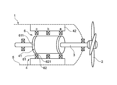
Fig. 1 shows a portion of a pod unit 1 for propulsion of a marine vessel in
arctic seas,
where the propeller blades 2 of the pod unit may hit ice or other hard objects
or be
grounded. In addition to the propeller, the pod unit 1 comprises a stiff drive
shaft 3
connecting an electric motor 4 to the propeller. The motor 4 is placed inside
a housing 5
and comprises a rotor 41 and a schematically shown stator 42. The rotor 41 and
the
shaft 3 form an assembly that is carried in bearings. When the propeller
blades 2 hit ice
or some other hard object, a high shock load is encountered, which tends to
momentarily bend the rotor shaft assembly, so that the rotor 41 may come into
contact
with the stator 42 and damage the motor 4 unless prevented from doing so.
CA 02847390 2014-02-28
WO 2013/039443 PCT/SE2012/050951
4
In accordance with the present invention, the rotor 41 is prevented from
coming in
detrimental contact with the stator 42 by providing at least two members 61,
62, which
together form a radial plain bearing 6 having mating arcuate bearing surfaces
611 and
621, respectively, which during normal operation of the motor 4 are spaced
from one
another by a non-conductive gap, e.g. a gas gap, preferably an air gap, and
come in
contact with one another only at extreme loads with short durations. One of
the
members 61, 62 is an inner member 61 having a circular circumference that
constitutes
one 611 of the bearing surfaces 611, 621. The arcuate bearing surface 611 of
the inner
member 61 is coaxial with the rotor 41 and rotary therewith, and at least one
of the other
members is an outer member 62, which is fixed in relation to the stator 42 and
has its
arcuate bearing surface 621 coaxial therewith.
When the propeller blades 2 hit ice blocks or other hard objects, and the
arising extreme
loads with short durations bend the rotor shaft assembly to such an extent
that the rotor
41 will tend to come into detrimental contact with the stator 42, the
detrimental contact
is prevented in that the inner member 61 of the radial plain bearing 6 will
bear against
the outer member(s) 62.
The radial plain bearing 6 may be located at any axial location along the
shaft rotor
assembly (between positions a and c in Fig.1), but for maintenance purposes it
is best to
locate it at an end of the motor 4. Usually, it is preferred to locate it at
the end closest to
the propeller (at position a in Fig.1), where also the bending of the shaft
will be at a
maximum. In case the loading condition is not bending but shock loads, it may
be
preferable to provide two radial plain bearings located at positions a and c
in Fig. 1.
Suitably, one of the at least two members 61, 62 consists of a softer material
than the
other, and the softer material is non-conductive to electricity. Thereby, when
the bearing
surfaces 611 and 621 are in contact with each other, no conductive material
will come
loose from the softer bearing surface and be spread inside the pod 1 where it
might harm
the motor 4 or other components.
The softer material preferably is used for the outer member(s) 62. The stator
42 includes
windings 421, and segments 622 of the softer material are fitted between the
windings
421 of the stator 42 as shown in Fig. 2a or on top of the windings 421 of the
stator 42 as
shown in Fig. 2b. Alternatively, the softer material is fitted as a
circumferential band
623 on the inner surface of the stator 42 as shown in Fig. 2c. Then, the
radial plain
CA 02847390 2014-02-28
WO 2013/039443 PCT/SE2012/050951
bearing 6 is formed by two complete rings 61 and 623 instead of one ring 61
and a
plurality of ring segments 62.
As another alternative, not shown, the member 62 of softer material is fixed
to the pod
5 housing 5.
It is easily realized that when one 62 of the at least two members 61, 62
consists of a
softer material, the other one 61 of the at least two members 61, 62 consists
of a harder
material. Suitably, the harder material is used for the inner member 61, and
the inner
member is a ring 61.
Preferably, the rotor 41 includes windings 411, and the ring 61 of the harder
material is
either provided on top of the windings 411 of the rotor 41 or is an integrated
part of the
rotor 41, or a ring (or two, or more) at an end of the rotor.
Alternatively, the ring 61 of the harder material is a dedicated device of the
motor 4 or
the shaft 3 fitted there for another main purpose, such as a brake disc, as is
shown in
Fig. 3. The ring 61 may be a solid disc or a ring attached to the shaft 3, by
means of
spokes or the like. The outer member 62 may be fixedly attached to a fixed
part of the
motor 4, e.g. forming the inner surface of a part of a housing (not shown), or
fixed to
the POD-housing (directly or indirectly, not shown).
The ring 61 may also be arranged on the periphery of a flange coupling (not
shown) of
the shaft 3.If desired, it is possible to let the ring 61 and the ring
segments 62 changes
places, so that the ring segments 62 are provided on the rotor 41 and the ring
61 is
provided on the stator 42. It is also possible, if desired, to use the harder
material for the
bearing member(s) provided on the stator 42 and the softer material for the
bearing
member(s) provided on the rotor 41.
The above detailed description is primarily intended only to facilitate the
understanding
of the invention, and any unnecessary limitations shall not be interpreted
therefrom.
Modifications, which during a study of the description become obvious to a
person
skilled in the art, may be made without any deviations from the inventive idea
or the
scope of the appended claims, e.g. it is evident that also bearing members of
the same
material/hardness may be used. Similarly it is evident that also conductive
members
may be used to fulfill the basic function of the invention.
CA 02847390 2014-02-28
WO 2013/039443 PCT/SE2012/050951
6
INDUSTRIAL APPLICABILITY
The present invention is applicable for preventing detrimental contact between
rotor and
stator in a pod motor for a marine vessel for use in arctic seas, where the
pod propeller
may hit ice blocks or other hard object, thereby creating shocks that will
tend to
momentarily bend the pod shaft.