Note: Descriptions are shown in the official language in which they were submitted.
CA 02847537 2014-03-03
WO 2013/034936
PCT/GB2012/052654
LIFTING BAR AND LIFTING BAR CONNECTOR
[0001]
Technical Field
[0002] The present disclosure is directed to a lifting bar and lifting
bar connector and,
more particularly, to lifting bar and lifting bar connector for use with
patient lifts.
Background
[0003] A patient lift may include a track-riding motor unit configured to
ride along an
elongated track. The track may be suspended to descend from a ceiling or other
elevated
structure, which may occupy less space in a room than another lift, such as, a
floor lift. A
load supporting member, for example, a flexible member such as a strap or
cable, may extend
from the motor unit and may be wound and unwound to raise and lower a lifting
bar. The
lifting bar can be secured to a sling, cradle, or other patient support for
supporting a patient.
A caregiver may use a control unit to control the motor unit to ride along the
track and/or
raise or lower the lifting bar in order to move the patient as desired.
[0004] A variety of lifting bars and lifting bar operations may be
available depending
on how the patient lift is to be used, i.e., depending on how the patient is
to be supported
and/or moved. The caregiver may replace one lifting bar with another by
disconnecting a
lifting bar from the load-supporting member and connecting another lifting bar
to the load-
supporting member.
[0005] As one example, U.S. Patent No. 7,434,787 ("the '787 patent)
describes a
ceiling lift having a winch that can be attached to an overhead rail. A
lifting strap projects
from the winch, and has a free end that is attached to a spreader bar.
According to the '787
patent, the extremities of the spreader bar are provided with hooks for
attaching a sling or the
like holding a patient to be lifted. The spreader bar is directly connected to
the winch at a
female seat, and there is a quick coupling system provided at the spreader bar
and the free
end of the lifting strap. The winch may be activated to wind the strap to lift
the spreader bar
attached thereto.
[0006] As another example, U.S. Patent Application Publication No.
2010/0064432
("the '432 publication") describes a patient lifting device for displacing
persons between
1
CA 02847537 2014-03-03
WO 2013/034936
PCT/GB2012/052654
various positions or areas. The device includes a lift strap extending from a
housing to a
lifting frame. The '432 publication further discloses that a sling may be
removable attached
to the lifting frame.
[0007] Thus, there is a need for an improved lifting bar and lifting bar
connector that
is more efficient and convenient to use in a medical lift system.
Summary
[0008] In one aspect, a patient lift connector for attaching and
detaching a patient
lifting bar to a load supporting member in a patient lifting system is
described. The
connector includes a connector body including a connecting block configured to
be fixedly
attached to the patient lifting bar. The connector also includes a pin holder
coupled to the
load supporting member and configured to be inserted through the connector
body and into
the connecting block, and an attachment latch secured to the connector body
and configured
to move between an open position and a closed position within the connector
body. When
the attachment latch moves from the closed position to the open position, the
pin holder is
allowed to be inserted into the connecting block and thereby allow the lifting
bar to be
attached to the load supporting member.
[0009] In another aspect, a patient lift connector for attaching a
patient lifting bar to a
load supporting member in a patient lifting system is described. The connector
includes a
connector body including a connecting block configured to be fixedly attached
to the patient
lifting bar. The connector also includes a terminating component of the load
supporting
member that is configured to be inserted through the connector body and into a
slot of the
connecting block, and an attachment latch secured to the connector body and
configured to
move between an open position and a closed position within the connector body.
The
terminating component is configured to move the attachment latch from the
closed position to
the open position to cause attachment of the lifting bar to the load
supporting member, and
the slot of the connecting block is covered by another part of the connector
body.
[0010] In yet another aspect, a method for attaching a patient lifting
bar to a load
supporting member in a patient lifting system through the use of a connector
is described.
The method includes pressing a terminating component of the load supporting
member
against an attachment latch of the connector, wherein the attachment latch is
secured to a
2
CA 02847537 2014-03-03
WO 2013/034936 PCT/GB2012/052654
connector body configured to be connected to the lifting bar. The method
further includes
moving the terminating component through a part of the connector body and into
a slot of a
connecting block. The attachment latch is configured to move between an open
position and
a closed position within the connector body, such that the attachment latch
moves to the open
position when the terminating component is pressed against the attachment
latch and wherein
the attachment latch moves to the closed position when the terminating
component moves
along the slot of the connecting block.
Brief Description of the Drawings
[0011] The accompanying drawings, which are incorporated in and
constitute a part
of this disclosure, illustrate various embodiments and aspects of the present
devices and
methods. In the drawings:
[0012] FIG. 1 is a perspective view of a ceiling lift system consistent
with the
embodiments disclosed herein;
[0013] FIG. 2 is a front view of a lifting bar according to a first
exemplary
embodiment;
[0014] FIG. 3 is a bottom view of the lifting bar of FIG. 2;
[0015] FIG. 4 is a partially cutaway perspective view of a lifting bar
according to a
second exemplary embodiment;
[0016] FIG. 5 is a view of a cover disposed on the lifting bar of FIG. 1;
[0017] FIG. 6 is an exploded view of the lifting bar connector consistent
with the
disclosed embodiments and shown as connected to the lifting bar of FIG. 4;
[0018] FIG. 7 is an assembled view of the lifting bar connector of FIG.
6;
[0019] FIG. 8 illustrates the attachment of a load supporting member to
the assembled
lifting bar connector of FIGS. 6 and 7;
[0020] FIG. 9 illustrates the detachment of a load supporting member from
the
assembled lifting bar connector of FIGS. 6 and 7.
[0021] FIG. 10 is a perspective view of a lifting bar according to a
third exemplary
embodiment;
[0022] FIG. 11 is a perspective view of a lifting bar according to a
fourth exemplary
embodiment;
3
CA 02847537 2014-03-03
WO 2013/034936
PCT/GB2012/052654
[0023] FIG. 12 is a perspective view of a lifting bar according to a
fifth exemplary
embodiment;
[0024] FIG. 13 is a perspective view of a lifting bar according to a
sixth exemplary
embodiment; and
[0025] FIG. 14 is a perspective view of a lifting bar according to a
seventh exemplary
embodiment.
Detailed Description of Example Embodiments
[0026] The following description should be read with reference to the
drawings
wherein like reference numerals indicate like elements throughout the several
views. The
detailed description and drawings illustrate example embodiments of the
claimed device(s)
and method(s).
[0027] FIG. 1 illustrates a perspective view of a ceiling lift system 2
consistent with
exemplary embodiments described herein. The lift system 2 may include a track
system 4
suspended from and extending along a ceiling or other wall or elevated
structure, and a
ceiling lifter 6 may move along the track system 4. The lifter 6 may be
manually movable
along the track system 4, or the lifter 6 may be a motorized unit
automatically movable along
the track system 4. A load supporting member 10 may extend from the ceiling
lifter 6. In
some instances, the load supporting member 10 may extend from an internal
space of the
ceiling lifter 6, wherein the load supporting member 10 is configured to be
wound and
unwound by the lifter 6 in order to raise and lower a lifting bar 12. In some
instances, the
load supporting member 10 may be a flexible load supporting member, such as a
strap, cable,
rope, or cord, or the load supporting member 10 may be a rigid supporting
member made of
metals and/or hard plastics, or the like.
[0028] The lifting bar 12 may be connected to the load supporting member
10 via a
connector 60, which is described in more detail with respect to FIGS. 6-8.
Although the
ceiling lift system 2 shown in FIG. 1 includes the lifting bar 12 according to
a first exemplary
embodiment, another lifting bar embodiment, such as the lifting bar 112 of a
second
exemplary embodiment described herein with respect to FIGS. 4, 6, and 7, may
also be used.
Furthermore, either lifting bar 12 or 112 may also be referred to as a
supporting bar, a
spreader bar, a lifting member, or the like. Additionally, a patient support
8, such as a sling,
4
CA 02847537 2014-03-03
WO 2013/034936
PCT/GB2012/052654
cradle, or other device, may be connected to the lifting bar 12 for movably
supporting a
patient. The patient support 8 may also be referred to herein as a patient
lift apparatus. The
lift system 2 may further include a control unit (not shown), such as a wired
or wireless
handheld button controller, for electrically communicating with the lifter 6
to instruct the
lifter 6 to ride along the track system 4 and/or raise or lower the lifting
bar 12 to move a
patient supported in the patient support 8.
[0029] FIG.
2 shows a front view of the lifting bar 12 separated from the ceiling lift
system 2 shown in FIG. 1. The lifting bar 12 may be an elongated member that
includes an
elongated main body 13, which may include ridges 17 and 18 protruding from one
or more
sides of the lifting bar 12. The lifting bar 12 can also include support
connectors 14
extending from opposite ends of the main body 13. The support connectors 14
may be hooks,
clasps, clips, or any other supporting and/or fastening member. Each support
connector 14
may include an end 16 having an aperture 19 extending therethrough. As shown
in FIG. 2, in
some instances, the end 16 may be rounded, such that it exhibits a spherical
or cylindrical
shape. The aperture 19, which may either extend all the way through the end 16
or only a
portion of the way through the end 16, is configured to receive a component,
such as a safety
mechanism 28. The support connectors 14 can allow connection of the load
supporting
member 10 to the lifting bar 12 (FIG. 1). As described in more detail below,
the support
connectors 14 can be formed into the main body 13 of the lifting bar 12 so
that the lifting bar
12 is a single element. The support connectors 14 may each form or define a
space 26 for
receiving a portion of the patient support 8. The space 26, which may also be
referred to as a
depression, socket, gap, or the like, can include a supporting surface 24
located on an inner
side of each support connector 14. The safety mechanism 28, which can be a
latch, clasp,
fastener, or other similar movable mechanism, can be movably attached to the
support
connector 14 to prevent the patient support 8, such as a strap of a sling in
contact with the
supporting surface 24, from unintentionally exiting the space 26.
[0030]
Although two support connectors 14 are shown in FIG. 2, additional support
connectors 14 could be formed as part of the lifting bar 12. The main body 13
of the lifting
bar 12 also includes a first surface 21 and a second surface 23 on an opposite
side of the main
body 13 as the first surface 21. Because the lifting bar 12 may be arranged in
the ceiling lift
system 2 as shown in FIG. 1, the first surface 21 may be referred to as an
upper surface, and
the second surface 23 may be referred to as a lower surface.
CA 02847537 2014-03-03
WO 2013/034936
PCT/GB2012/052654
[0031] As shown in FIGS. 2 and 3, the lifting bar 12 may have a length
200 extending
from an outermost edge of one support connector 14 to an outermost edge of
another support
connector 14 disposed on an opposite end of the main body 13 of the lifting
bar 12. In some
instances, the length 200 may be between about 30.5 and 61.0 cm (between about
12.0 and
24.0 inches). For example, in one implementation, the length 200 may be about
45.7 cm
(about 18.0 inches). The lifting bar 112 of FIGS. 4, 6, and 7 may have
dimensions similar to
those of the lifting bar 12. These values are examples only, as the lifting
bars 12, 112 may
have a variety of other lengths depending on, for example, the size of the
patient to be
supported by the ceiling lift system 2.
[0032] FIG. 3 shows a bottom view of the lifting bar 12 shown in FIG. 2,
that is, the
second (lower) surface 23 shown in FIG. 3. The lifting bar 12 can include a
lifting bar
aperture 29, which can be a through-hole extending from the lower surface 23
to the upper
surface 21 and configured to receive a lifting bar pin 130 (FIGS. 4 and 6).
Although the
lifting bar aperture 29 shown in FIG. 3 is circular, other shapes could be
provided, such as,
oval-like or rectangular to accommodate lifting bar pins having a variety of
cross-sectional
shapes. Additionally, while the lifting bar aperture 29 is shown in FIG. 3 at
a location at or
near the middle of the length 200 of the lifting bar 12, other types of
apertures may be used.
For example, the lifting bar 12 may include two apertures equally spaced from
the center of
the lifting bar 12.
[0033] FIG. 4 is a partially cutaway perspective view of a lifting bar
112 separated
from the ceiling lift system 2 according to another example embodiment. The
lifting bar 112
may be an elongated member. However, while the lifting bar 12 depicted in
FIGS. 2 and 3
may be manufactured as a single, solid component, the lifting bar 112 shown in
FIG. 4 may
also include an inner core 150 extending through portions of a separate
lifting bar main body
113 and/or portions of one or more support connectors 114. The portion of the
inner core 150
extending through and surrounded by one or more support connectors 114 may be
referred to
as the inner core support connectors 162. The inner core 150 may have a
variety of
configurations to extend through any portion of the main body 113 and support
connectors
114 of the lifting bar. The inner core 150 may be made of any material; for
example, durable
materials such as metals or hard plastics. In some instances, the inner core
150 may be
referred to as a metallic beam. Also, in some embodiments, the material from
which the
inner core 150 is made is harder than the material forming the lifting bar
main body 113 and
6
CA 02847537 2014-03-03
WO 2013/034936 PCT/GB2012/052654
support connectors 114, which together may be referred to as a skeletal
support structure for
the inner core 150.
[0034] The inner core 150 may include a plurality of sheets. For example,
inner core
150 may include a first sheet 152 and a second sheet 154 having faces in
contact with one
another. The sheets 152, 154, which may also be referred to as plates, may be
connected via
any fastening or adhering configuration, such as welding, riveting, or
applying an adhesive on
the contacting faces. In some instances, the sheets 152, 154 forming the inner
core may be
metallic or made from a hard plastic. FIG. 4 shows the inner core 150 formed
of a plurality
of layered sheets 152, 154. Flanges 156, 158, 160 may extend from the sheets
152, 154. As
shown in FIG. 4, a first flange 156 extends from the first sheet 152, and
second and third
flanges 158, 160, respectively, extend from the second sheet 154. A fourth
flange (not
shown) may extend from the first sheet 152 in a direction opposite the third
flange 160. The
inner core 150 may also include holes 164, which may be retaining pin holes,
formed in the
inner core 150 so that the inner core 150 can be held in place during a
molding process,
which is described in more detail below. Although the inner core 150 is
described herein as
having various features, the inner core can have other shapes and features,
and/or be made of
a material other than metal. Also, as described in more detail below, the
inner core 150 can
have a shape and features similar to the lifting bar main body 113 and
supporting connectors
114 that are formed over the inner core 150.
[0035] The lifting bar main body 113 may include a first, or upper,
surface 121 and a
second, or lower, surface 123 located opposite the first surface 121. A first
ridge 117 and a
second ridge 118 may protrude from one or more sides of the lifting bar 112.
Additionally,
the lifting bar 112 can include strips 125 and/or holes extending along the
length of the lifting
bar 112, which may be the result of a first molding process, and which can be
filled in with a
material during a second molding process, as described in more detail below.
[0036] As described herein, the lifting bar 112 can include support
connectors 114 at
opposite ends of the main body 113. The support connectors 114 may be hooks,
clasps, clips,
or any other supporting and/or fastening member. Each support connector 114
may include
an end 116 having an aperture 119 extending therethrough. As shown in FIG. 4,
in some
instances the end 116 may be rounded, such that it exhibits a spherical or
cylindrical shape.
The aperture 119, which may either extend all the way through the end 116 or
only a portion
of the way through the end 116, is configured to receive a component, such as
a safety
7
CA 02847537 2014-03-03
WO 2013/034936
PCT/GB2012/052654
mechanism 102 (FIG. 6). The support connectors 114 can allow connection of the
load
supporting member 10 (FIG. 1) to the lifting bar 112. As described in more
detail below, the
support connectors 114 can be formed with the main body 113 of the lifting bar
112 so that
the main body 113 and support connectors 114 are a single element. The support
connectors
114 may each form or define a space 126 for receiving a portion of the patient
support 8. The
space 126, which may also be referred to as a depression, socket, gap, or the
like, can include
a supporting surface 124 located on an inner side of each support connector
114. Although
two support connectors 114 are shown in FIG. 4, additional support connectors
114 could be
formed as part of the lifting bar 112.
[0037] Similar to the lifting bar 12 as illustrated in FIG. 5, the safety
mechanism 102,
such as a safety latch, may prevent the patient support 8 from unintentionally
detaching from
the lifting bar 112. The safety mechanism 102 may have various configurations
that reduce
the likelihood that the patient support 8 will unintentionally detach from the
lifting bar 112,
while allowing for intentional detachment of the patient support 8 from the
lifting bar 112.
As shown in FIG. 6, the safety mechanism 102 can be secured to either the
support connector
114, for example, at the end 116 of the support connector through the aperture
119, or to the
lifting bar body 112. The safety mechanism 102 may also be formed integrally
with the
lifting bar main body 113 or with the support connector 114. This integral
formation may
ensure that there are no interruptions, such as gaps or other joints, between
the safety
mechanism 102 and the lifting bar main body 113 or the support connector 114.
[0038] The lifting bar 112 may include a lifting bar aperture 129 for
receiving a
lifting bar pin 130. Similar to the lifting bar aperture 29 of the lifting bar
12 shown in FIG. 3,
the lifting bar aperture 129 can be a through hole extending from the lower
surface 123 to the
upper surface 121. Additionally, as shown in FIG. 4, the lifting bar pin 130
may include a
lifting bar pin aperture 140 configured to receive a connecting block pin 90
therethrough
(FIG. 6).
[0039] FIG. 5 shows a cover 27 removably disposed on the lifting bar 12
of FIG. 1.
The cover 27 may be any type of removable protective padding to cover at least
a portion of
the lifting bar 12. For example, the cover 27 may cover a substantial amount
of the main
body 13 of the lifting bar 12, while leaving the support connectors 14
uncovered. The cover
27 may be wrapped or secured around the lifting bar 12 in a number of ways,
for example,
using a fastening device such as a zipper or hook-and-loop fasteners disposed
along a side of
8
CA 02847537 2014-03-03
WO 2013/034936
PCT/GB2012/052654
the cover 27. Although the cover 27 is shown as being disposed on the lifting
bar 12, the
cover 27 may also be used to cover the lifting bar 112 shown in FIGS. 4, 6,
and 7.
[0040] FIG. 6 shows an exploded view of an exemplary connector 60 for the
lifting
bar 112 shown in FIG. 4. Although the connector 60 is shown as being connected
to the
lifting bar 112, the following description related to the lifting bar 112 and
the lifting bar
connector 60 may also be applicable to the lifting bar 12 shown in a described
with respect to
FIGS. 1-3 and 5. As described herein, a safety mechanism 102, such as a latch,
can be
provided with the lifting bar 112. The safety mechanism 102, which can be
connected to a
safety mechanism spring 104, may be connected to the end 116 of the support
connector 114
via a safety mechanism pin 106. When assembled (FIG. 7), the spring 104 can
bias the safety
mechanism 102 to a closed position in which the safety mechanism contacts the
main body
113 of the lifting bar 112 (FIG. 7). Providing the described safety mechanism
102
arrangement, including the spring 104, can reduce the likelihood that the
patient support 8
will unintentionally detach from the lifting bar 112, while allowing for
intentional
detachment of the patient support 8 from the lifting bar 112.
[0041] The connector 60 may include the load supporting member 10, for
example, a
flexible load supporting member such as a strap. In some instances, a portion
of the load
supporting member 10 may be a slot 15 for receiving a pin holder 20. The slot
15 and pin
holder 20 may be collectively referred to as a terminating component of the
load supporting
member, a terminating member, or the like. In some embodiments, the slot 15
may be
replaced with a clasp, hook, buckle, or any other connecting or affixing
mechanism capable
of interfacing with a connecting block cover 35 and/or a connecting block 65,
either directly
or via another component, such as the pin holder 20. The pin holder 20 may
include a pin
holder drum 25 configured to receive a pin 30 therethrough, and a pair of
wings 22. The pin
holder 20 may alternatively or additionally include a clasp, hook, buckle, or
any other
connecting mechanism suited to interface with the connecting block cover 35
and/or the
connecting block 65. In some instances, the pin holder drum 25 and pin 30 may
be
integrated. Additionally, in an example embodiment, the pin holder drum 25 may
be formed
as a separate component, and may be hingedly secured to a pin holder to allow
the pin holder
and the pin holder drum 25 to be adjustable.
[0042] The connector 60 may include a connector body, which, in some
instances, is
comprised of the connecting block cover 35 and the connecting block 65. The
connecting
9
CA 02847537 2014-03-03
WO 2013/034936
PCT/GB2012/052654
block cover 35 may have a block cover socket 40 for receiving the connecting
block 65 and
the pin holder drum 25 therein. The connector body may also include indents 45
in the block
cover 35 formed in a surface thereof, which allow the pin holder drum 25 and
pin 30 to pass
therethrough. First pin apertures 50 of the block cover 35, also referred to
as latch pin
apertures 50, may be configured to receive latch pins 110 therethrough, and
second pin
apertures 55 of the block cover 35, also referred to as connecting block cover
pin apertures,
may be configured to receive a connecting block pin 90 therethrough. The
connecting block
pin 90 may also be configured to receive a connecting block pin cover 95
therethrough. The
block cover socket 40 may be situated at any position in the connecting block
cover 35, for
example, along another desired axis. It can have any configuration capable of
accepting all
or a portion of the connecting block 65 therein, and the connecting block 65
may be non-
removably received within the block cover socket 40. The block cover indents
45 may have
any desired configuration that allows a portion of the pin holder 20, pin
holder drum 25,
and/or load supporting member 10 to pass. In some instances, however, the
block cover
indents 45 may not allow another portion of the pin holder 20 to pass
therethrough. The
block cover indents 45 can be formed in any portion of the connecting block
cover 35 and are
not limited to being formed in both sides of the cover 35 or in the front of
cover 35. For
example, one or more indents, apertures, or openings could allow the load
supporting
member 10 to be inserted from the side of the connecting block cover 35. In
some
embodiments, the block cover indents 45 may not be formed in cover 35, and may
be
additionally or alternatively formed in the connecting block 65. The block
cover first pin
apertures 50 may be any mechanism for interfacing with an attachment latch
100, and may
include, for example, spring-biased surfaces that secure the attachment latch
100 to either the
connecting block cover 35 or the connecting block 65 by sandwiching a portion
of the
attachment latch 100. The block cover second pin apertures 55 and/or a
connecting block
second apertures 85 can alternatively or additionally include any mechanism
for securing the
connecting block cover 35 and the connecting block 65 together. For example,
spring-biased
surfaces configured to squeeze portions of the connecting block cover 35
and/or the
connecting block 65 may be provided in place of the connecting block pin 90.
[0043] As shown in FIG. 6, the connecting block 65 may include one or
more slots 32
for receiving a portion of the pin holder 20 and/or the load supporting member
10. For
example, the pin 30 may be received within the slots 32. The connecting block
65 may also
CA 02847537 2014-03-03
WO 2013/034936 PCT/GB2012/052654
include a connecting block socket 70 and a connecting block cavity 80 for
receiving the pin
holder drum 25 and the pin 30 therein. A connecting block first aperture 75
may be provided
for receiving a lifting bar pin 130 therethrough. Also, the connecting block
second apertures
85, which may be referred to as connecting block apertures, may be provided
for receiving a
connecting block pin 90 therethrough. In some instances, the connecting block
65 and the
connecting block cover 35 are integrated into one component by, for example,
providing the
connecting block 65 with a block cover first pin aperture. The connecting
block socket 70
can be situated at any position in the connecting block 65. For example,
socket 70 may open
along another desired axis. The connecting block socket 70 may have any
configuration
capable of accepting all or a portion of the pin holder 20 (including the pin
holder drum 25),
the load supporting member 10, and/or the pin 30. In some instances, the
connecting block
65 and/or the connecting block cover 35 are not secured to the lifting bar 112
using a lifting
bar pin 130. Instead, for example, these components may be molded together as
integrated
components, such that the lifting bar pin 130 is not necessary.
[0044] The connector 60 can further include an attachment latch 100
having latch
flanges 105 that may be complimentary to the block cover indents 45 such that
the latch
flanges may fit within the block cover indents 45. Latch pins 110 of the
attachment latch 100
may be receivable within the block cover first pin apertures 50. The
attachment latch 100
may further include an attachment latch main body 120, which, in some
embodiments, can
have a finger depression formed therein, and an attachment latch biasing
element 115, such as
a spring, for biasing the attachment latch 100 towards a "closed" position. In
the closed
position, the latch flanges 105 can abut the connecting block cover 35 at the
block cover
indents 45. The attachment latch 100 may not be hingedly or swingably secured
to the
connecting block cover 35 or the connecting block 65 in some instances. The
attachment
latch 100 may instead have, for example, a push-button configuration in which
the latch 100
opens and closes by being pressed into the connecting block socket 70, rather
than
"swinging" into the connecting block socket 70. Alternatively, the attachment
latch 100 may
swing along a different axis or edge. The latch pins 110 may be replaced with
any
connecting, fastening, or securing mechanism for securing the attachment latch
100 to the
connecting block cover 35. For example, rather than latch pins 110 being
received within the
block cover first pin apertures 50, a portion of the attachment latch 100 may
be slid into a
latch pocket or similar structure formed in the connecting block cover 35 or
connecting block
11
CA 02847537 2014-03-03
WO 2013/034936
PCT/GB2012/052654
65. In some instances, an additional latch may be provided in the connecting
block socket 70
to control the movement of the pin holder drum 25 while the pin holder drum 25
is situated in
the connecting block socket 70.
[0045] The lifting bar 112 may be integrated with the connecting block 35
and/or the
connecting block cover 65. Additionally, the connector 60 described herein or
the various
components that comprise the connector 60 can be sculpted, carved, or
otherwise formed in
the lifting bar 112. For example, the load supporting member 10 can be secured
to the lifting
bar 112 by inserting a portion of the member 10 into the connecting block
socket 70 that may
be carved into the lifting bar 112, for example, by pushing an attachment
latch secured to the
lifting bar 112. A thrust bearing may also be provided between the lifting bar
pin 130 and the
lifting bar 112 to ease rotation between the lifting bar pin 130 and the
lifting bar 112. As
shown in FIG. 6, the lifting bar pin 130 can include a lifting bar pin
aperture 140 configured
to receive the connecting block pin 90 therethrough. Although FIG. 6
illustrates the
connector 60 being used with the lifting bar 112 shown in FIG. 4, the
connector 60 may also
be used with the lifting bar 12 shown in FIGS. 1-3 and 5, or with various
other lifting bar
embodiments.
[0046] Referring to the assembled connector 60 in FIG. 7, which shows the
attachment latch 100 in the closed position, the connecting block 65 shown in
FIG. 6 is
situated in the connecting block cover 35, and the connecting block 65 and
block cover 35 are
secured to the lifting bar 112 using the lifting bar pin 130. The load
supporting member 10
having the pin holder 20 within the slot 15 is secured to the lifting bar 112
via the connecting
block 65 and block cover 35. The attachment latch main body 120 covers the
connecting
block socket 70, and the latch flanges 105 cover the block cover indents 45
(FIG. 6). This
configuration may help to secure the load supporting member 10 by preventing
the pin holder
drum 25 from being moved out of the connecting block socket 70 via the block
cover indents
45. The attachment latch 100 may be spring biased using the attachment latch
biasing
element 115, such that the attachment latch 100 can swing in a forward
direction to move the
attachment latch main body 120 and the latch flanges 105 into the connecting
block socket
70. In some instances, however, the attachment latch 100 may be prevented from
swinging
further in an opposite backward direction than the closed position, which may
help maintain
the pin holder drum 25 and pin 30 within the connecting block socket 70.
12
CA 02847537 2014-03-03
WO 2013/034936 PCT/GB2012/052654
[0047] Referring to FIG. 8, to secure the load supporting member 10 to
the lifting bar
112, part of the terminating component, such as the pin holder 20 or pin
holder drum 25, may
be pressed against the attachment latch main body 120, as shown by arrow 300,
to swing the
attachment latch 100 into the connecting block socket 70. Doing so moves the
attachment
latch 100 between an open position and the closed position, for example, from
the closed
position to the open position. In some instances, the pin holder drum 25 can
be pressed
against the attachment latch main body 120 in a direction that is
substantially perpendicular
to the connecting block 65, as shown in FIG. 8. The attachment latch 100,
however, can be
spring biased against the open position, that is, biased to the closed
position. Therefore, once
the pin holder drum 25 and pin 30 have been moved past the attachment latch
100, the
attachment latch 100 swings back into the closed position such that the
flanges 105 of the
attachment latch 100 abut the block cover indents 4, as shown in FIG. 7. The
load supporting
member 10, the pin holder 20, and/or the pin 30 can then be lifted upwardly
and slide into
slots 32, as shown by arrow 302. After being lifted and with the attachment
latch 100 in the
closed position, the load supporting member 10, pin holder 20, and/or pin 30
may be rotated
within the slots 32 in a first direction approximately 90 , as shown by arrow
304, thereby
positioning the wings 22 at least partly above the connecting block cover 35.
Once the wings
22 are in place, the pin holder 20 may resist downward motion as the wings 22
abut the top of
the connecting block cover 35. In this manner, the load supporting member 10
can be
secured to the connecting block 65, which is secured to the connecting block
cover 35 and the
lifting bar 112. In some instances, the attachment latch 100 may remain in the
open position
until the load supporting member 10, pin holder 20, and/or pin 30 is rotated
within the
connector block 65 so that the wings 22 abut the top of the connecting block
cover 35.
Although the lifting bar 112 is shown in FIG. 8, the attachment (and
detachment) methods
described herein may be applied to the lifting bar 12 of FIG. 2 in a similar
manner.
[0048] Referring to FIG. 9, to detach the load supporting member 10 from
the lifting
bar 112, the attachment latch 100 may be pressed or pushed forwards, as shown
by arrow
306, manually by a user or automatically, into its open position. When the
attachment latch
100 is pressed, the load supporting member 10 may be detached from the
connecting block
65 by, for example, rotating the load supporting member 10, the pin holder 20,
and/or the pin
30 within the slots 32 in a second direction downwardly approximately 90 , as
shown by
arrow 308, thereby helping to clear the wings 22 from the top of the
connecting block cover
13
CA 02847537 2014-03-03
WO 2013/034936
PCT/GB2012/052654
35. In some instances, when the attachment latch 100 is pressed, the load
supporting member
may be detached from the connecting block 65 by lowering or moving (e.g.,
sliding) the
load supporting member 10, the pin holder 20 , or the pin 30 in a downward
direction within,
for example, the slots 32 of the connecting block cover 65, as shown by arrow
310. This
method of detachment may allow the load supporting member 10, the pin holder
20, and/or
the pin 30 to be separated from the connecting block 65 by moving the pin
holder drum 25
and pin 30 out of the connecting block cavity 80 and past the block cover
indents 45, as
shown by arrow 312. In some instances, the load supporting member 10, pin
holder 20, and
pin 30 may be moved in a direction that is substantially perpendicular to the
connecting block
65 during detachment. Once the pin holder drum 25 and the pin 30 have moved
past the
block cover indents 45, the attachment latch 100 can be allowed to return to
its closed
position.
[0049] Various modifications of the devices and methods described herein
may be
provided. For example, the connector 60, and more specifically the connector
body, may be
provided without the connector block cover 35 for covering the connector block
65. If no
connector block cover 35 is provided, other portions of the connector 60, such
as the
connector block 65, may include any of the features of the connector block
cover 35. For
example, the connector block 65 can be configured to receive and/or support
the attachment
latch 100 by having additional apertures or depressions configured to receive
the latch pins
110 to rotatably support the attachment latch 100 in the connector block 65.
[0050] Additionally, the pin holder 20 and/or load supporting member 10
may be
provided with a mechanism to change the width or other dimension(s) of the pin
holder drum
25, such that the pin holder drum 25 may pass into the connecting block socket
70 as desired.
For example, the pin holder 20, pin holder drum 25, and/or load supporting
member 10 may
include a retractable, spring-biased flange that includes a portion that is
external to the pin
holder drum 25. By pressing, for example, a button or the flange itself, the
flange can retract
in an inward direction, partly or entirely into the pin holder 20, pin holder
drum 25, and/or
load supporting member 10, thereby allowing manipulation of the dimensions of
the pin
holder 20, pin holder drum 25, and/or load supporting member 10. This may
allow the pin
holder 20, pin holder drum 25, and/or load supporting member 10 to fit past an
opening, such
as the block cover indents 45, that opens onto the connecting block socket 70.
When the
flange is in the connecting block socket 70, the flange may be released or
otherwise allowed
14
CA 02847537 2014-03-03
WO 2013/034936
PCT/GB2012/052654
to protrude again, which can prohibit the pin holder 20, pin holder drum 25,
and/or load
supporting member 10 from exiting the connecting block socket 70 until the
flange is again
retracted.
[0051] Additionally, the lifting bars 12, 112 described herein can have a
variety of
other configurations capable of interfacing with the ceiling lift system 2.
For example, the
lifting bars 12, 112 can include multiple bars, connectors, sockets,
apertures, and the like.
Furthermore, the lifting bars 12, 112 may be integrated with the load
supporting member 10,
or at least a portion thereof so as to provide a smooth and uninterrupted
transition from the
load supporting member 10 to the lifting bars 12, 112.
[0052] FIGS. 10-14 depict a variety of additional embodiments of the
lifting bar.
FIG. 10 illustrates a third example embodiment of a lifting bar 212 according
to the present
disclosure. The lifting bar 212 includes a main body 213 having curved
structural members
222, a cross member 224, a supporting member 216, and a connecting member 226.
The
curved structural members 222 may extend through an opening 228 in the
supporting
member 216. In some instances, the opening 228 is a through hole extending
entirely
through the supporting member 216, in which case the plurality of curved
structural members
222 may be provided as a single structural member 222 connecting to opposite
ends of the
cross member 224. The lifting bar 212 may also include support connectors 218.
The
support connectors 218 may extend from the main body 213 and include a variety
of
configurations, such as the spherical configuration shown in FIG. 10, that may
function as
safety mechanisms and help retain a patient support attached to the lifting
bar 212. In some
instances, the lifting bar 212 may also include a handle 220 for maneuvering
the lifting bar
212. A lifting bar aperture 229 may be formed in the supporting member 216 for
receiving a
lifting bar pin to connect the connector 60 to secure the lifting bar 212 to
the load supporting
member 10.
[0053] FIG. 11 shows a fourth example embodiment of a lifting bar 311
according to
the present disclosure. The lifting bar 311 includes a plurality of elongate
members 313
extending from a central structure 318, which may be collectively referred to
as a main body.
Each elongate member 313 may terminate in a support connector 314 having a
movable
safety mechanism 316, such as a latch, a clamp, or the like. To allow for
connection to an
apparatus such as the ceiling lift system 2 shown in FIG. 1, the central
structure 318 of the
lifting bar 311 may include a lifting bar aperture 329. The lifting bar
aperture 329 may be
CA 02847537 2014-03-03
WO 2013/034936
PCT/GB2012/052654
configured to receive a lifting bar pin to connect to the connector 60 so that
the lifting bar 311
may be securely connected to the load supporting member 10.
[0054] FIG. 12 shows a fifth example embodiment of a lifting bar 412
according to
the present disclosure. The lifting bar 412 includes a plurality of elongate
members 413
extending from a central structure 418, which may be collectively referred to
as a main body.
Each elongate member 413 may terminate in a support connector 414 having a
movable
safety mechanism 416, such as a latch, clamp, or the like. To allow for
connection to an
apparatus such as the ceiling lift system 2 shown in FIG. 1, the central
structure 418 of the
lifting bar 412 may include a lifting bar aperture 429. The lifting bar
aperture 429 may be
configured to receive a lifting bar pin to connect to the connector 60 so that
the lifting bar 412
may be securely connected to the load supporting member 10.
[0055] FIG. 13 illustrates a sixth example embodiment of a lifting bar
512 according
to the present disclosure. The lifting bar 512 includes an elongated main body
513, which
terminates at two opposite ends with support connectors 514. Each support
connector 514
may include a safety mechanism 516, such as a latch, clamp, or the like. The
lifting bar 512
may also include a raised member 527, which can act as an additional support,
cover, or
handle for a person operating the ceiling lift system 2 when the lifting bar
512 is installed.
The raised member 527 may be formed either separately from or integrally with
the main
body 513. At a central position along the main body 513, a lifting bar
aperture 529 may be
provided for receiving a lifting bar pin to connect the connector 60, so that
the lifting bar 512
may be securely connected to the load supporting member 10.
[0056] FIG. 14 shows a seventh example embodiment of a lifting bar 612
according
to the present disclosure. The lifting bar 612 includes a main body 613, which
may be
formed of a plurality of connecting members. Extending members 622 extend from
opposite
ends of the main body 612, and a plurality of support connectors 614 may be
provided at
different positions along the extending members 622. As shown in FIG. 14,
additional
support connectors may also be provided on portions of the main body 613. The
support
connectors 614 may each include a safety mechanism 616 configured to securely
retain, for
example, the patient support 8 when the lifting bar 612 is in use. An
additional supporting
member 618 may extend from the main body 613 and be connected to a central
structure 615.
In some instances, as shown in FIG. 14 the additional supporting member 618
may extend in
a plane that is substantially perpendicular to a plan in which the main body
613 and the
16
CA 02847537 2014-03-03
WO 2013/034936 PCT/GB2012/052654
extending members 622 are located. The central structure 615 may include a
lifting bar
aperture 629, which may be configured to receive a lifting bar pin to connect
the lifting bar
612 to the connector 60 so that the lifting bar 612 may be securely connected
to the load
supporting member 10. The various components of the lifting bar 612, such as
the main body
613, the additional supporting member 618, and the extending members 622, may
be formed
as bars having rectangular cross-sectional shapes, circular cross-sectional
shapes, or any other
cross-sectional shape.
[0057] Like the lifting bars 12, 112, either of which may be used with
the connector
60, any of the lifting bars show in FIGS. 10-14 may also be used with the
connector 60 and
incorporated into the ceiling lift system 2 shown in FIG. 1.
[0058] The various lifting bars and the connector 60 described herein may
be used
with a ceiling lift or other lifting device to removably secure various
components and devices
together in a variety of medical and nonmedical settings. In a medical
setting, for example,
the ceiling lift system 2 can support a patient in the patient support 8, such
as a sling. Using,
for example, a controller (not shown) electrically connected to the ceiling
lifter 6, an operator
can move the lifting bars and load supporting member 10 via the lifter 6. When
the patient is
supported in the patient support 8 that is attached to the lifting bars, the
patient can be moved
vertically and/or horizontally. The lifter 6 may function as a winch or
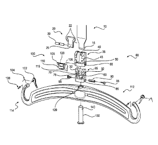
similar crank device
such that winding takes up more of the load supporting member 10 to raise the
patient,
whereas unwinding may let out the load supporting member 10 to lower the
patient. Moving
the lifter 6 along the track system 4 can also allow for horizontal and/or
vertical movement.
[0059] The various lifting bars described herein may be manufactured
using various
methods. For example, the lifting bars illustrated in FIGS. 1-3 and 5, 11, 12,
and 13 may be
entirely manufactured by injection molding in a single step. Referring to the
lifting bar 12
shown in FIGS. 1-3 and 5 for example, the main body 13 and support connectors
14 can be
manufactured in one step and at the same time, such that the lifting bar 12 is
a single,
continuous elongated member. As used herein, the term "continuous" as it
refers to the
structure of the lifting bar 12 may indicate that the lifting bar 12 is an
elongate member
without breaks, joints, or the like between the main body 13 and the support
connectors 14.
The lifting bar 12 may be molded to be completely solid, that is, not having
any open spaces
within the lifting bar main body 13 and the support connectors 14 (other than
the apertures
19). In other instances, however, the lifting bar 12 may be molded around a
core such that
17
CA 02847537 2014-03-03
WO 2013/034936
PCT/GB2012/052654
there may be empty or hollow spaces within the lifting bar 12. Additional
steps, for example,
abrasion techniques such as sanding, may be taken after the single molding
step to further
smooth the outer surface of the lifting bar 12. While the safety mechanism 28
may also be
manufactured in the single injection molding step used to produce the lifting
bar 12, in some
instances, the safety mechanism 28 may be produced separately from the lifting
bar 12.
When the safety mechanism 28 is produced separately, it may be secured to the
lifting bar 12
after the injection molding step is complete.
[0060] With respect to the lifting bar illustrated in FIGS. 4, 6, and 7,
the lifting bar
112 may be manufactured in two injection molding steps. The inner core 150 may
first be
secured in place by connecting retaining pins through the various retaining
pin holes 164.
These retaining pins (not shown) may hold the lifting bar 112 in place during
at least a first
step of the injection molding process. During the first step, the material,
such as a thermo-
plastic, can be over-molded around the entire inner core 150 to form a capsule
such that the
inner core 150 is encapsulated or surrounded by the molded material. Because
the inner core
150 is held in place by the retaining pins, however, unfilled space, or holes,
may exist where
the retaining pins were located. The retaining pins can be removed after the
first molding
step and, during a second step of the injection molding after the first step,
additional material
can be injected to mold the lifting bar main body 113, the support connectors
114, and/or the
safety mechanism 102. In some instances, the safety mechanism 102 is produced
separately
from the injection molding steps, such that the safety mechanism 102 may be
secured to the
lifting bar 112 after the two injection molding steps are complete. The second
step of the
injection molding may also fill in the spaces formed by the retaining pins.
The second step
may result in a strip 125 of material being formed along one or more portions
of the lifting
bar 112. In some instances, the material used during the first and second
steps may be the
same material. In other instances, however, the material used to fill in the
spaces left by the
retaining pins in the second step may be different from the material used to
mold the main
body 113 and support connectors 114 during the first step. If, for example, an
undesired strip
of material or imperfection results from the two injection molding steps,
additional steps,
such as abrasion techniques like sanding, may be taken to smooth the outer
surface of the
lifting bar 112.
[0061] In any of the described methods of manufacturing the lifting bars,
the resultant
surface finish of the lifting bars may be non-porous, cavity-free, and/or
smooth. The lifting
18
CA 02847537 2014-03-03
WO 2013/034936
PCT/GB2012/052654
bar 12 as shown in FIG. 2, for example, may be manufactured in one injection
molding step
as a single continuous element having few, if any, cavities and/or other
details on its surface.
While the lifting bar 112 as shown in FIG. 4 may be manufactured in multiple
steps, it can
also exhibit a smooth, generally cavity-free surface finish.
[0062] Hygiene can be important in preventing the spread of disease in
medical
settings. To prevent cross-contamination of infected surfaces and other
structures, caregivers
must be diligent in cleaning equipment and areas accessible to patients by,
for example, using
a known disinfectant. The described lifting bars may be subject to
manipulation in a patient
room, for example, such that it is important to reduce the risk of cross-
contamination. The
lifting bars may facilitate the ease with which the lifting bars can be
cleaned, which can
reduce the time needed for cleaning, thereby enhancing efficiency and lowering
costs. The
smooth, non-porous surface finish of the lifting bars can also allow for
better cleaning results,
resulting from a quick and continuous cleaning movement that can be employed,
which can
in turn decrease the spread of disease. The lifting bars described herein may
be provided
without having one or more of the following: details such as steps between
various profiles
forming the lifting bar body or other small, hard-to-reach features;
separately connected
support connectors; joints or junctions that may create cavities that can be
difficult to
effectively clean; or the like. For example, the single-element design of the
lifting bar 12,
manufactured in a single step as described herein, can contribute to the
smooth surface finish
and the ease with which the lifting bar 12 is cleaned. The lifting bar 112 of
FIG. 4, which
may be manufactured in multiple steps, can also have a smooth, uninterrupted
surface finish
allowing for easy cleaning. Furthermore, in instances when the lifting bars
are integrated
with the load supporting member 10, the integration can result in a structure
that requires less
effort to effectively clean. The spaces, such as spaces 26, 126 defined by the
support
connectors 14, 114, of lifting bars 12, 112, respectively, can also be large
enough and smooth
so as to be easily accessible to, for example, a caregiver, so that the
caregiver may manually
clean the support connector 14, 114, including the supporting surface 24, 124,
and to enable
insertion or attachment of the patient support 8 to the lifting bars 12, 112.
In addition to the
lifting bar, the hand control (not shown) can also include a smooth, flexible
membrane, rather
than highly texturized control buttons. This can facilitate the ease with
which the hand
control is cleaned, while providing a hand control that is easy to use,
ergonomic, aesthetic,
compact, and that has a generally low manufacturing cost.
19
CA 02847537 2014-03-03
WO 2013/034936
PCT/GB2012/052654
[0063] During a medical procedure, safety, efficiency, and cleanliness
are often
important for the caregiver to provide effective care to a patient. This is
especially true as the
number of patients and procedures a caregiver is responsible for increases.
During
procedures where a lift device may be used, a lifting bar, such as the various
lifting bars
described herein, may need to be repeatedly connected and disconnected to and
from a load
supporting member. The lifting bar connector 60 described herein may be a
compact and
easy-to-clean device that enables fast, easily initiated, and sturdy
connection and/or
disconnection between various load supporting members and lifting bars. The
lifting bar
connector 60 can allow for quick replacement of a lifting bar with another
similar or different
lifting bar in a manner that is intuitive and safe for the patient and
caregiver. Moreover, the
connector 60 may not significantly reduce the lifting stroke, that is, the
vertical distance in
which the lifting bar and attachments may travel, of the ceiling lift system
2. Additionally,
the smooth or streamlined design of the connector 60, particularly the
connecting block cover
35, may allow for simple and effective cleaning of the connector 60 and
surrounding area.
Because the connector 60 may be frequently handled by a person during
connection and
disconnection of the various lifting bars, easy and complete cleaning of the
connector 60 and
surrounding area can be important to preventing the spread of disease.
[0064] The attaching and detaching sequence described herein may be
generally
quick and simple, as it involves a clipping action as the load supporting
member 10, pin
holder 20, and pin 30 are pushed to or pulled away from the connecting block
65 of the
connector 60. The attachment method may be especially convenient because there
is no need
to first unlock a device before the attachment. The attachment latch 100 being
biased to the
closed position, for example, allows for attachment of the load supporting
member 10, pin
holder 20, and pin 30 without having to unlock any portion of the device,
while securely
retaining these elements within the connecting block 65. While there is no
"unlocking"
required prior to attachment, because the attachment latch 100 is biased to
the closed position
(e.g., by using the attachment latch spring 15), the attachment latch 100 may
function as a
safety device that resists accidental detachment of the load supporting member
10, pin holder
20, and pin 30 from the lifting bars. As described herein, a safety measure is
incorporated
into the present device and method by requiring manual, voluntary action to
achieve
detachment.
CA 02847537 2014-03-03
WO 2013/034936
PCT/GB2012/052654
[0065] It will be apparent to those skilled in the art that various
modifications and
variations can be made to the disclosed apparatus and method. Other
embodiments will be
apparent to those skilled in the art from consideration of the specification
and practice of the
disclosed system and method. It is intended that the specification and
examples be
considered as exemplary only, with a true scope being indicated by the
following claims and
their equivalents.
21