Note: Descriptions are shown in the official language in which they were submitted.
CA 02847593 2015-11-17
1
PCT PATENT APPLICATION
METHOD AND APPARATUS FOR
UNPLUGGING HYDROCARBON DRAINS OR VENTS
BACKGROUND OF THE INVENTION
1.
[00011
2. Field of the Invention
10002 j The present invention relates to closed hydrocarbon systems. More
specifically, the
invention relates to an apparatus and method for unplugging drains or vents in
hydrocarbon
systems.
3. Description of the Related Art
100031 In hydrocarbon industrial areas, while preparing a section of a live
pipeline for
maintenance, it is mandatory to ensure that the isolated segnient is
completely depressurized and
free from any hydrocarbon toxic or combustible gases. Gasses such as H2S,
which may he
present in the pipeline, are one of the deadliest hazards in the oil and gas
industry. The usual
current practice is to connect the live process pipeline vents or drains to a
closed system to
extract all combustible and toxic gases. However, the vents or drains of the
process lines may he
plugged over time preventing the proper, complete, and safe drainage of the
liquids.
10004] Connecting the pipe to a closed system by itself will not unplug the
pipe because pressure
gauges alone will not indicate if line is clear or plugged. Therefore when
preparing a section of
pipeline for maintenance operations, it is common to manually open the drain
or vent to the
CA 02847593 2014-03-03
WO 2013/039943 PCT/US2012/054713
2
atmosphere to ensure they are not plugged. If the vent or drain is plugged,
then the operator will
have to poke through it to remove any particles or sludge that has built onto
the drain or vent.
This practice not only poses a great deal of risk of harm for th.e operator,
it also has the potential
to contaminate the environment. If the operator is not equipped with the
needed personal
protection equipment, such as a self-contain.ed breathing apparatus, he will
be exposed to high
concentrations of toxic fumes that have a deadly effect on his health as well
as being a source of
ignition during the cleaning process.
[0005] lt would therefore be beneficial to have an apparatus and method for
unplugging vents
and drains that does not expose the operator to combustible and toxic gases
nor release them into
the environm.ent.
SUBSTITUTE SHEET (RULE 26)
CA 02847593 2014-03-03
WO 2013/039943 PCT/US2012/054713
3
100061 SUMMARY OF THE INVENTION
100071 Embodiments of the current application provide a system and method for
mechanically
cleaning debris from vents and drains for isolating segments of a hydrocarbon
unit for
maintenance purposes, while containing any contaminants in a closed system.
100081 In one embodiment of the current application an apparatus for
unplugging a component
of a hydrocarbon transportation or storage unit includes a main body, the main
body comprising:
a central passage through a length of the main body; a secondary passage
transverse to the
central passage; a connector end operable to connect the body to the drain or
vent. The apparatus
further includes a valve in fluid communication with the secondary passage; a
pressure gauge in
fluid communication with the valve; a system connector in fluid communication
with the valve,
operable to connect the apparatus to a closed system; and a poker rod operable
to move within
the central passage of the main body.
100091 In another embodiment of the current application, the poker rod
includes a crash head
operable to move into the vent or drain for removing a blockage therein. The
poker rod can
further include external threads on an (Ma surface and a handle. The central
passage can further
include internal threads on an inner surface which engage the external threads
of the poker rod.
100101 In other embodiments, a packing creates a seal between the poker rod
and the central
passage. The packing can be a high pressure rated packing suitable for use
with hydrocarbons.
A cap can be located adjacent to the packing, and the apparatus can further
include a pushing nut
for maintaining the position of the cap.
100111 In alternative embodiments, the component can be a vent or a drain, the
valve can be a
high pressure valve and the gauge can be a high pressure gauge.
100121 In another embodiment of the current application, a method for
unplugging a component
connected to a fluid transportation or storage unit, useful in hydrocarbon
application, includes
the steps of, (a) connecting a component connector end of a device to the
component; (b)
connecting a system connector end of the device to a closed system; (c)
opening a device outlet
valve (d) poking an end of a rod of the device into the component; (e)
evaluating if a pressure
gauge of the device reads a pressure greater than zero; and (0 repeating step
(d) and step (e) until
the pressure gauge reads a pressure greater than zero.
SUBSTITUTE SHEET (RULE 26)
CA 02847593 2015-11-17
4
[0013] In some embodiments, after step (b), a device valve of the device, a
component
valve of the component and a closed system valve are opened. After step (f),
the device
valve of the device, the component valve of the component, and the closed
system valve
can be closed. After step (f), the device can be disconnected from the
component and
the closed system when the pressure read by the pressure gauge is
substantially equal to
zero.
[0014] In alternative embodiments, the component connector end of the device
and the
system connector end of the device are in fluid communication, and any fluids
passing
through the device in the closed system can be collected in the closed system.
The
component can be a vent or a drain, and step (b) can further include clearing
debris
from the component.
[0015] In yet another embodiment of the current application, a method for
unplugging a
component connected to a fluid transportation or storage unit, useful in
hydrocarbon
application, comprising the steps of: (a) connecting a component connector end
of a
device to the component, the device comprising a poker rod operable to enter
the
component; (b) connecting a system connector end of the device to a closed
system; (c)
evaluating if a pressure gauge of the device reads a pressure greater than
zero; (d)
monitoring the pressure gauge until the pressure becomes substantially equal
to zero;
and (e) disconnecting the device from the component and the closed system.
[0016] In alternative embodiments after step (b), the poker rod is moved into
the
component to clear a blockage. After step (b), a device valve of the device, a
component valve of the component, and the closed system valve can be opened.
After
step (d), the device valve of the device, the component valve of the component
and the
closed system valve can be closed.
[0017] In other alternative embodiments, the component connector end of the
device
and the system connector end of the device can be in fluid communication, and
the
method can further include the step of collecting any fluids passing through
the device
CA 02847593 2015-11-17
4A
in the closed system. The component can be a vent or drain, and the method can
further
include the step of after step (b) clearing debris from the component with the
poker rod.
10017A] In other alternative embodiments, an apparatus for unplugging an
outlet and
venting or draining a fluid through the outlet is disclosed, the apparatus
including a
main body which comprises a central passage through a length of the main body,
the
central passage being coaxial with an outlet, a secondary passage extending
transverse
to, and from the central passage through a first side of the main body, and a
connector
end operable to connect the body to the outlet, the connector end being
coaxial with the
central passage. The apparatus further includes a valve in fluid communication
with the
secondary passage, the valve joined with and spaced from, the first side of
the main
body. A pressure gauge is included and is in fluid communication with the
valve, the
pressure gauge joined with and spaced from, the first side of the main body. A
closed
system is included and is in fluid communication with the valve through a
system
connector, and a poker rod operable to move axially along the central passage
of the
main body.
10017B1 In other alternative embodiments, a method for unplugging a component
connected to a fluid containing unit and venting or draining a fluid from the
fluid
containing unit through the component is disclosed, the method useful in
hydrocarbon
application, and comprising the steps of: (a) connecting a component connector
end of a
device to the component, the device having: a central passage through a length
of a
main body, a secondary passage extending transverse to, and from the central
passage
through a first side of the main body, a device valve in fluid communication
with the
secondary passage, the device valve joined with and spaced from, the first
side of the
main body, and a pressure gauge in fluid communication with the device valve,
the
pressure gauge joined with and spaced from, the first side of the main body,
(b)
connecting a system connector of the device to a closed system, (c) poking an
end of a
rod of the device axially through the central passage and into the component,
(d)
evaluating if the pressure gauge reads a pressure greater than zero, (e)
repeating step (c)
CA 02847593 2015-11-17
4B
and step (d) until the pressure gauge reads a pressure greater than zero, and
(f) passing
fluid through the device from the fluid containing unit and into to the closed
system.
[0017C] In other alternative embodiments, a method for unplugging a component
connected to a fluid containing unit and venting or draining a fluid from the
fluid
containing unit through the component is disclosed, the method useful in
hydrocarbon
application, and comprising the steps of: (a) connecting a component connector
end of a
device to the component, the device comprising: a central passage through a
length of a
main body, a secondary passage extending transverse to, and from the central
passage
through a first side of the main body, a device valve in fluid communication
with the
secondary passage, the device valve joined with and spaced from, the first
side of the
main body, and a pressure gauge in fluid communication with the device valve,
the
pressure gauge joined with and spaced from, the first side of the main body,
and a poker
rod operable to move axially along the central passage and enter the
component, (b)
connecting a system connector of the device to a closed system, (c) evaluating
if a
pressure gauge of the device reads a pressure greater than zero, (d) passing
fluid
through the device from the fluid containing unit and into to the closed
system, (e)
monitoring the pressure gauge until the pressure becomes substantially equal
to zero,
and (f) disconnecting the device from the component and the closed system.
CA 02847593 2014-03-03
WO 2013/039943 PCT/US2012/054713
BRIEF DESCRIPTION OF THE DRAWINGS
[00181 So that the manner in which the above-recited features, aspects and
advantages of the
invention, as well as others that will become apparent, are attained and can
be understood in
detail, a more particular description of the invention briefly summarized
above may be had by
referen.ce to the embodiments thereof that are illustrated in the drawings
that fonm a part of this
specification. It is to be noted, however, that the appended drawings
illustrate only preferred
embodiments of the invention and are, therefore, not to be considered limiting
of the invention's
scope, for the invention may admit to other equally effective embodiments.
[00191 FIG. 1 is a sectional view of an einbodiment of the device of the
current application.
[00201 FIG, 2 is a section view of the body of the device of FIG I.,
[00211 FIG. 3 is a perspective view of the device of FIG 1.
[00221 FIG, 4 is a flow diagram of the steps of a, method of the current
application,
SUBSTITUTE SHEET (RULE 26)
CA 02847593 2014-03-03
WO 2013/039943 PCT/US2012/054713
6
DETAILED DESCRIPTION OF THE EXEMPLARY EMBODIMENTS
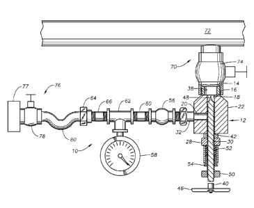
[0023i Turning to FIG 1, a device 10 includes a body 12. Body 12 includes a
main section 22,
which can be solid. Body 12 has a component connector end 14 which can have
connector 16
for connecting the body 12 to a component, such as, for example, outlet 70.
Outlet 70 can be a
vent or drain of a fluid containing unit, such as a fluid transportation or
storage unit. Pipeline 72
is an example of a fluid containing unit and can be, for example, pipe or
tubing. In
embodiments, pipeline 72 can be a hydrocarbon pipeline used to transport,
store, or produce
hydrocarbons. Alternatively, the component, such as outlet 70, can be part of
any other
apparatus that can contain fluid such as, for example, a heat exchanger, a
storage vessel, a
reaction vessel, a tank, or other fluid production, transportation or storage
unit. In embodiments,
outlet 70 can be part of a hydrocarbon storage or production apparatus.
[00241 Connector 16 can be connected to, for example, outlet 70. Connector 16
can be a
threaded connection, such as the external threads shown in FIG 1. Depending on
the
specification of the components of outlet 70, connector 16 can include
internal threads, a quick
connect, or other fitting. Alternatively, connector 16 can require an adaptor
to connect body 12
to the outlet 70. Connector 16 has a connector passage 38. Outlet 70 can
include a valve 74, can
be used to selectively prevent fluid from passing through outlet 70 until
valve 74 is opened.
When connector 16 is connected to outlet 70, and valve 74 is opened, fluid can
be communicated
through outlet 70 to connector passage 38 of connector 16.
100251 Body 12 has a central passage 18 that runs through the length of main
section 22. A
portion of the internal wall of passage 18 can be a smooth cylindrical bore. A
lower end of
central passage 18 can extend beyond main section 22 to form a rod receptor
24. A portion of an
outer surface of rod receptor 24 can include external threads 26. Rod receptor
24 can also
include a nut 28 with interior threads 30 that protrude within central passage
18. The upper end
of central passage 18 is in fluid communication with connector passage 38 of
connector 16.
100261 Body 12 also has a secondary passage 20 which can be generally
transverse to central
passage 18. One end of secondary passage 20 intersects with central passage 18
and the other
end of secondary passage 20 extends beyond main section 22 to form a valve
receptor 32. A
SUBSTITUTE SHEET (RULE 26)
CA 02847593 2014-03-03
WO 2013/039943 PCT/US2012/054 7 13
7
portion of an outer surface of valve receptor 32 can have external threads 34.
A nut 36 can be
situated on the exterior of valve receptor 32.
100271 Returning to FIG 1, a rod 40 is located within central passage 18. Rod
40 can have
external threads 42 which mate with internal threads 30 of nut 28 to direct
rod 40. Rod 40 will
have an outer diameter smaller than the internal diameter of central passage
18 such that threads
42 will not come into contact with inner diameter 44 of central passage 18.
Rod 40 can also
include a crash head 48 at an end which is proximate to connector 16 and a
handle 46 at its other
end. An end of crash head 48 can be larger in diameter than an external
diameter of internal
threads 30 so that the crash head 48 will not easily come out of body 12 past
internal threads 30.
A seal, such as packing 52, suitable for the type of fluid to be vented or
drained by device 10,
such as hydrocarbon, and having a high-pressure rating can be located within
rod receptor 24.
Packing 52 is contained between a portion of rod receptor 24 adjacent an
outward side of nut 28
and a cap 54, which is situated proximate to the lower end of rod receptor 24
and creates a seal
between rod 40 and central passage 18. Packing can be formed of a deformable
material and
compressed to provide an effective pressure seal between the fluid in body 12
and the outside
atmosphere. A pushing nut 50 can be used to secure and stress the cap 54 so
that cap 54
maintains packing 52 in a compressed state. In alternative embodiments,
pushing nut 50 can be
threaded onto external threads 26 (best shown in Figure 2). Other types of
seals can be used to
seal the annulus between rod receptor 24 and rod 40.
[0028] A valve 56 can be connected to valve receptor 32 and is in fluid
communication with
secondary passage 20. As seen in FIG 3, valve 56 can have a handle 58 which
allows an
operator to open and close the passage through the valve. Valve 56 can be, for
example, a high-
pressure rate stainless steel isolation valve with female connectors at both
ends.
100291 Returning to FIG 1, device 10 also includes a pressure gauge 58.
Pressure gauge 58 is in
fluid communication with valve 56, either directly, or as shown in FIG 1, by
way of a threaded
nipple 60 and threaded tee connector 62, or other connection means. Nipple 60,
connector 62
and any other connector can be high-pressure rate stainless steel components.
Pressure gauge 58
can be a high pressure gauge.
100301 Device 10 can also include a system connector 64, which can be used to
connect device
to a closed system 76. System connector 64 can be a high pressure rate union
connector, as
SUBSTITUTE SHEET (RULE 26)
CA 02847593 2014-03-03
WO 2013/039943 PCT/US2012/054713
8
shown in FIG 1. Depending on the specification of the components of the closed
system 76 to be
used with the device, system connector 64 can include external threads,
internal thread, a quick
connect, or other fitting. Closed system 76 is a fluid disposal system, or
fluid receiving system,
that can be used to contain fluid that is drained or vented through device 10
from outlet 70.
Closed system 76 can include, for example, a receptacle 77, which can include
a vessel, vacuum
source, pump, or other apparatus suitable for accepting fluid and preventing
fluid from leaking or
otherwise escaping into the atmosphere. The closed system 76 can include a
closed system valve
78, which can be opened or closed by the operator. Closed system 76 can also
include taking 80
which can be connected to system connector 64. System connector 64 can require
an adaptor to
connect device 10 to the closed system 76. System connector 64 is in fluid
communication with
valve 56 and can be connected directly to valve 56, directly to pressure gauge
58 or can be
connected by way of threaded =nipple 66 or other connector.
[00311 Turning to FIG 4, in operation, the first step 100 is to connect the
device 10 to outlet 70
of tubing 72, and to closed system 76. Looking at FIG 1, connector end 1.4 of
body 12 makes the
connection with the outlet 70 and system connector 64 makes the connection
with the closed
system 76. At this point, both the valve 74 that is part of the outlet 70 and
valve 56 are closed.
[00321 Returning to FIG 4, the next step 102 is to open the valve 56, then the
valve 78 associated
with the closed system 76, then the valve 74 associated with the outlet 70.
Looking once again at
FIG 1, valve 56 is in fluid communication with secondary passage 20, which in
turn is fluid
connmunicafion with central passage 18. Therefore any fluids within the tubing
72 can now pass
into central passage 18, and through valve 56. If the outlet 70 is clear,
pressure gauge 58, which
is also in fluid communication with valve 56, will read pressure.
[00331 Returning to FIG 4, the next step 104 is therefore to check if pressure
gauge 58 reads
pressure greater than zero. If the answer is yes, the operator next executes
step 108. If the
answer is no, the operator executes step 106. In step 106, the operator uses
rod 40 to poke
through the outlet 70 to free any sludge or particles. In embodiments, rod 40
can pass through
valve 74, provided that valve 74 is open. Looking at FIG 1, by turning handle
46, the operator
can move rod 40 up and down relative to body 12. Crash head 48 will enter the
outlet 70,
including valve 74, through connector passage 38, and mechanically free the
outlet 70 of the
sludge, particles or other blockage.
SUBSTITUTE SHEET (RULE 26)
CA 02847593 2014-03-03
WO 2013/039943 PCT/US2012/054713
9
PA Returning once again to FIG 4, after executing step 106, the operator will
then return to
step 104 and once again determine if pressure gauge 58 reads pressure. If the
answer is still no,
the operator once again executes step 106 of poking through the outlet 70 and
step 104 of
determining if pressure gauge 58 reads pressure until such time as the
operator can answer yes to
the question of step 104, that the pressure gauge 58 reads pressure. At that
point, the operator
executes step 108.
100351 In step 108, the operator monitors pressure gauge 56 (FIG 1) until the
pressure drops to
substantially zero. This pressure drop is an indication that the fluids within
the pipeline 72 have
been drained. Looking at FIG 1, the fluids in the pipeline 72 would pass
through the outlet 70
valve 74 into connector passage 38 of connector 14. These fluids are unable to
escape through
central passage 18 because packing 52 creates a seal sufficient to prevent the
fluids from
reaching the lower end of central passage 18. Fluids instead pass through
valve 56 and system
connector 64 and into the closed system 76. The fluids are collected in the
closed system 76,
keeping both the operator and the environment free of and safe =from any toxic
or combustible
gasses.
10036) Next the operator executes step 110 by closing the valve 74 connected
to the pipeline 72,
then the valve 78 associated with the closed system 76. Turning again to FIG
1, the operator also
closes valve 56 (FIG 1). Finally in step 112 of FIG 4, the operator then
disconnects the device 10
from both the closed system 76 and valve 74 of outlet 70.
100371 Although the present invention has been described in detail, it should
be understood that
various changes, substitutions, and alterations can be made hereupon without
departing from the
principle and scope of the invention. Accordingly, the scope of the present
invention should be
determined by the following claims and their appropriate legal equivalents.
[00381 The singular forms "a", "an" and "the" include plural referents, unless
the context clearly
dictates otherwise. Optional or optionally means that the subsequently
described event or
circumstances may or may not occur. The description includes instances where
the event or
circumstance occurs and instances where it does not occur. Ranges may be
expressed herein as
from about one particular value, and/or to about another particular value.
When such a range is
expressed, it is to be understood that another embodiment is from the one
particular value and/or
to the other particular value, along with all combinations within said range.
SUBSTITUTE SHEET (RULE 26)
CA 02847593 2015-11-17
10039] Throughout this application, where patents or publications are
referenced, the disclosures
of these references in their entireties may be referred to for further details
on the
pertinent art, in order to more fully describe the state of the art to which
the invention pertains,
except when these reference contradict the statements made herein.