Note: Descriptions are shown in the official language in which they were submitted.
CA 02847703 2014-03-05
WO 2013/037032
PCT/CA2011/050549
METHOD AND SYSTEM FOR MANAGING BANDWIDTH
TECHNICAL FIELD
[0001] The present disclosure relates to content delivery systems and, more
particularly, to methods and systems for managing bandwidth in content
delivery
systems.
BACKGROUND
[0002] Content delivery systems such as cable television systems, satellite
television
systems and Internet protocol television systems (IPTV) often deliver content,
such as
television programming from a head end system which is operated by a service
provider
to one or more receivers operating within the content delivery system.
[0003] Such content delivery systems often have a limited amount of bandwidth
available to deliver content. For example, wireless content delivery systems
such as
satellite television systems may be required to deliver signals within a
specific portion
of the wireless spectrum. Similarly, wired content delivery systems, such as
cable
television systems, operate over a wired transmission medium which has a
finite
amount of usable bandwidth.
[0004] The availability of bandwidth for content delivery may be further
limited
where service providers provide other services in addition to content delivery
system
services. For example, service providers may operate a voice communication
service
and/or an Internet service over a transmission medium which they also use for
content
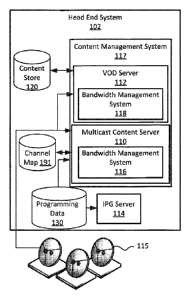
delivery system services (such as television delivery services). Each of these
services
may require bandwidth in the transmission medium, thus reducing the overall
availability of bandwidth in the transmission medium.
[0005] Thus there exists a need for systems and methods of managing bandwidth
in
content delivery systems.
BRIEF DESCRIPTION OF THE DRAWINGS
1
CA 02847703 2014-03-05
WO 2013/037032
PCT/CA2011/050549
[0006] FIG. 1 is a system diagram of an example content delivery system in
accordance with example embodiments of the present disclosure;
[0007] FIG. 2 is a system diagram of an example content delivery system in
accordance with example embodiments of the present disclosure;
[0008] FIG. 3 is a block diagram of an example head end system for use with a
content delivery system such as the content delivery systems of FIGs. 1 and 2;
[0009] FIG. 4 is a block diagram of an example receiver for use with a content
delivery system such as the content delivery systems of FIGs. 1 and 2;
[0010] FIG. 5 is a flowchart of a method for managing bandwidth in accordance
with
example embodiments of the present disclosure;
[0011] FIG. 6 is a flowchart of a method for managing bandwidth in accordance
with
example embodiments of the present disclosure;
[0012] FIG. 7 is a flowchart of a method for managing bandwidth in accordance
with
example embodiments of the present disclosure; and
[0013] FIG. 8 is a flowchart of a method for managing bandwidth in accordance
with
example embodiments of the present disclosure.
[0014] Like reference numerals are used in the drawings to denote like
elements
and features.
DETAILED DESCRIPTION OF EXAMPLE EMBODIMENTS
[0015] In one aspect, the present disclosure describes a method of managing
bandwidth in a content delivery system. The method comprises: identifying two
or
more content items which are associated with at least some common content and
which are temporally related; determining a relative priority of the least
some of the
identified content items; and allowing a receiver requesting the content
associated with
a lower priority content item to access a nnulticast associated with a higher
priority
content item.
2
CA 02847703 2014-03-05
WO 2013/037032
PCT/CA2011/050549
[0016] In another aspect, the present disclosure describes a bandwidth
management system. The bandwidth management system includes at least one
processor and a memory coupled to the at least one processor. The memory has
stored
thereon processor executable instructions which, when executed by the
processor
cause the processor to: identify two or more content items which are
associated with at
least some common content and which are temporally related; determine a
relative
priority of the least some of the identified content items; and allow a
receiver
requesting the content associated with a lower priority content item to access
a
nnulticast associated with a higher priority content item.
[0017] In yet another aspect, the present disclosure describes a receiver. The
receiver includes an input mechanism and at least one processor. The receiver
also
includes a memory coupled to the at least one processor. The memory has stored
thereon processor executable instructions which, when executed by the
processor
cause the processor to: in response to receiving a request for content
associated with a
first virtual channel from the input mechanism, providing content associated
with a
second virtual channel.
[0018] Other example embodiments of the present disclosure will be apparent to
those of ordinary skill in the art from a review of the following detailed
description in
conjunction with the drawings.
Example Wired Television System
[0019] Referring now to FIG. 1, a block diagram of an example content delivery
system 100 is illustrated in which example embodiments of the present
disclosure may
be applied. The content delivery system 100 is configured to deliver content
from a
content source system to a content destination system.
[0020] In the example embodiment illustrated, the system from which content is
delivered (i.e. the content source system) is referred to as a head end system
102 and
the system receiving the content (i.e. the content destination system) for
presentation
on a media player (such as a television), is referred to as a receiver 104. In
at least
some example embodiments, the content delivery system 100 is a broadcast
television
3
CA 02847703 2014-03-05
WO 2013/037032
PCT/CA2011/050549
system which delivers television content such as broadcast television shows.
The
content delivery system 100 is configured to deliver content over a broadcast
or
nnulticast domain 195 (which, for simplicity, will be referred to as a
broadcast domain
195). The broadcast or nnulticast domain 195 includes a plurality of receivers
104. In
the embodiment illustrated in FIG. 1, the broadcast domain 195 includes a
first receiver
104a, a second receiver 104b, and a third receiver 104c. The first receiver
104a, second
receiver 104b and third receiver 104c are connected to the head end system
102.
[0021] The content delivery system 100 may provide a subscription based
content
delivery service in which each receiver 104 operating in the content delivery
system 100
may be associated with a subscriber to the content delivery system 100. Each
subscriber may be authorized to view specific content. For example, each
subscriber
may be authorized to view a specific set of broadcast streams associated with
channels
which the subscriber subscribes to. The content delivery system 100 may
deliver
content to a plurality of subscribers associated with a plurality of receivers
104.
[0022] The head end system 102 may be owned and/or operated by a content
service provider including a television service provider such as a cable
television service
provider and/or a satellite television service provider. The head end system
102
broadcasts or nnulticasts content (such as television programming) to a
plurality of
receivers 104 located within a broadcast or nnulticast domain 195.
Multicasting content
refers to sending content to two or more receivers 104. Broadcasting content
refers to
sending content throughout the broadcast domain 195. Since such a broadcast
may be
received by two or more receivers, the term nnulticasting as used herein may
also
include broadcasting.
[0023] The receivers 104 are typically located in a location associated with
subscriber, such as, for example, the home of a subscriber. Accordingly, in at
least
some example embodiments, the receivers 104 may be referred to as Customer
Premises Equipment (CPE). The receivers 104 may be connected to a media
player,
such as a television, on which content received at the receiver 104 may be
displayed. In
at least some example embodiments, a receiver 104, or parts thereof, may be
internal
to a media player (e.g. the television). For example, a receiver 104 may be a
4
CA 02847703 2014-03-05
WO 2013/037032
PCT/CA2011/050549
component of a television which is included in the television at the time of
manufacture. In other embodiments, a receiver 104 may be an external receiver
104
which is connected to the media player (e.g. the television) through a wired
or wireless
transport medium.
[0024] The plurality of receivers 104 operating within the broadcast domain
195
may include, in at least some example embodiments, one or more set top boxes.
A set
top box is a device which connects to a television (or other display) and an
external
source of signal, turning the signal into content which may be displayed on
the
television (or other display). The term set top box includes devices which do
not,
necessarily, sit on top of a television. That is, the term set top box may
refer to any
device which is external to a television (or other display) and which receives
an external
signal, turns the signal into content and displays the signal on the display.
[0025] The receivers 104 operating within the broadcast domain 195 may also
take
other forms including, for example, a gaming console, a cable card, a personal
computer, a tablet device, a snnartphone, etc. The receivers 104 may be any
electronic
devices at which content from a head end system 102 may be received.
[0026] The receivers 104 are connected to the head end system 102 through a
transport medium 197 which may, in various embodiments, be a wired transport
medium (such as coaxial cable and/or fibre optic cable) or wireless transport
medium
197 (such as radio frequency (RF) based transport mediums). Depending on the
transport medium 197 used to transport the content from the head end system
102 to
receivers 104, the content delivery system 100 may, in various embodiments, be
a
wired television system 162 (FIG. 1), such as a cable television system, which
delivers
content to the receiver 104 over a wired transport 163 (such as coaxial cable
and/or
fibre optic cable), or a satellite television system 154 (FIG. 2) which
delivers content to
the receiver 104 over a satellite transport 155. The content delivery system
100 may
also be based on other broadcast or nnulticast based content delivery
technologies and
transport mediums apart from those specifically discussed herein.
5
CA 02847703 2014-03-05
WO 2013/037032
PCT/CA2011/050549
[0027] In FIG. 1, the content delivery system 100 is a wired television system
162,
such as a cable television system. The head end system 102 and the receivers
104
operating within the broadcast domain 195 are connected via a wired transport
163.
The wired transport 163 may include a cable. The wired transport 163 may, in
various
embodiments, include copper or other wires such as coaxial cable and/or may
include
an optical transport medium, such as fibre optic cables.
[0028] The head end system 102 and the receivers 104 are configured to permit
downstream communications to the receivers 104 through respective transport
mediums and protocols. More particularly, the head end system 102 and the
receivers
104 are configured to permit content, such as television content, to be
delivered to the
receivers 104 for display on media players (such as a television) associated
with
respective receivers. Where the content delivery system 100 is a wired
television
system 162, such as a cable television system, the head end system 102 may
deliver
content to the receiver 104 through the wired transport 163.
[0029] In at least some example embodiments, the content delivery system 100
provides for upstream communications from one or more of the receivers 104 to
the
head end system 102. In at least some example embodiments, upstream
communications (i.e. communications originating from a receiver 104 which are
sent to
the head end system 102) may operate on the same transport medium 197 and/or
transport protocol as the downstream communications (downstream communications
are communications originating from the head end system 102 which are sent to
one or
more receiver 104). For example, in a wired television system 162 such as a
cable
television system, communications originating from a receiver 104 may be sent
to the
head end system 102 through the wired transport 163. As will be illustrated in
the
example content delivery system 100 of FIG. 2, in at least some embodiments,
the
receiver 104 may be configured to send upstream communications over a
different
transport medium than the transport medium from which downstream
communications are received.
[0030] Accordingly, the head end system 102 and the receivers 104 used in the
content delivery systems 100 described above (i.e. the satellite television
system 154
6
CA 02847703 2014-03-05
WO 2013/037032
PCT/CA2011/050549
and the wired television system 162) provide for downstream communications
from the
head end system 102 to the receivers 104. In at least some example
embodiments, the
head end system 102 and the receivers 104 are also configured to provide
upstream
communications from the receivers 104 to the head end system 102. Such
upstream
communications may permit the receivers 104 to communicate with the head end
system 102. Such upstream communications may, for example, be useful to
provide
on-demand services to a receiver 104, such as video on-demand services (which
may be
used to deliver specific video content on request), audio on-demand services
(which
may be used to deliver specific audio content on request) or application on-
demand
services (which may be used to deliver specific applications on request) to a
receiver
104.
Example Satellite Television System
[0031] Referring now to FIG. 2, an example content delivery system 101
according
to other example embodiments of the present disclosure is illustrated. The
content
delivery system 101 of FIG. 2 illustrates a satellite television system 154.
The content
delivery system 101 of FIG. 2 includes a head end system 102 which is
connected to a
plurality of receivers 104 via a transport medium 197. The head end system 102
and
the receivers 104 may be of the types described above with respect to the
content
delivery system 100 of FIG. 1.
[0032] In the satellite television system 154, the head end system 102 may be
configured to deliver content to receivers 104 operating within the broadcast
domain
195 via a satellite transport 155. The satellite transport 155 may include a
satellite
uplink 156 connected to the head end system 102. The satellite uplink 156
(which may
include a satellite dish) transmits data (including content) to a satellite
157 placed in
orbit around the earth. The satellite 157 then transmits content to a receiver
104
through a satellite downlink 158 (which may include a satellite dish)
connected to the
receiver 104.
[0033] The satellite television system 154 may also allow for upstream
communications from one or more receivers 104 to the head end system 102. In
some
7
CA 02847703 2014-03-05
WO 2013/037032
PCT/CA2011/050549
such embodiments, communications originating from a receiver 104 may be sent
to the
head end system 102 through the satellite transport 155.
[0034] In other example embodiments, upstream communications (i.e.
communications originating from the receiver 104 which are sent to the head
end
system 102) may operate on a different transport medium and/or transport
protocol as
the downstream communications (i.e. communications originating from the head
end
system 102 which are sent to one or more receiver 104). By way of example, in
at least
some embodiments, the satellite downlink 158 may capable of receiving data
from the
satellite 157 but may not be capable of sending data to the satellite 157. In
such
embodiments, upstream communications from the receiver 104 to the head end
system 102 may be provided through an alternative transport medium such as a
wired
transport medium 159. In at least some embodiments, the wired transport medium
159 used for upstream communications in the satellite television system 154
comprises
twisted pair wiring. In some embodiments, the wired transport medium 159 used
for
upstream communications may be a transport medium over which packet based
communications may be transmitted. For example, the wired transport medium 159
may be any transport medium providing a connection to the Internet.
[0035] Accordingly, in at least some example embodiments, the receiver 104
and/or
the head end system 102 of a content delivery system 100 (FIG. 1), 101 (FIG.
2) may be
configured to communicate with one another over a wired transport medium which
may include, for example, a coaxial transport medium, an optical transport
medium
(such as fibre optic cable), a twisted pair transport medium such as telephone
cable
(including, for example, a category 1 cable (Cat 1)) or an Ethernet cable
(including, for
example, a category 5 cable (Cat 5) or category 6 cable (Cat 6)) which may
connect to
the head end system 102 through a network, such as the Internet. Similarly, in
some
embodiments, the receiver 104 and/or the head end system 102 may be configured
to
communicate with one another over a wireless transport medium such as a radio
frequency transport medium (including satellite based communications and/or
WiFi).
Example Head End System
8
CA 02847703 2014-03-05
WO 2013/037032
PCT/CA2011/050549
[0036] As noted above, the content delivery system 100 (FIG. 1), 101 (FIG. 2)
includes a head end system 102. Referring now to FIG. 3, a block diagram of an
example head end system 102 is illustrated. The head end system 102 is
configured to
gather content (such as programming sources including source broadcast
streams),
decode, select and/or retransmit such content (such as video programming) to a
distribution network, which includes one or more receivers 104. The content
which is
delivered to the head-end-system 102 may include, for example, broadcast or
nnulticast
content (such as broadcast video) and on-demand content (such as pay-per-view
content, including movies, special events, and other on-demand content). The
broadcast or nnulticast content which is delivered to the head end system 102
for
broadcasting and/or nnulticasting live to receivers may be referred to as
source
broadcast streams.
[0037] The head end system 102 may include or connect to a content acquisition
system 115. The content acquisition system 115 of FIG. 3 is illustrated as a
plurality of
satellite dishes. Such satellite dishes may be configured to receive content
from one or
more satellites. In various embodiments, the content acquisition system 115
may be
configured to receive content through other means instead of, or in addition
to, the
satellite dishes. For example, the content acquisition system 115 may include
one or
more antennas which receive radio frequency signals, such as signals
transmitted
through a terrestrial based network. In at least some embodiments, the content
acquisition system 115 may be configured to receive content through a network,
such
as the Internet. In at least some embodiments, the content acquisition system
115 may
be configured to receive content though a wired transport medium such as, for
example, a cable. The cable may, in some example embodiments, include a
coaxial
cable and/or a fibre optic cable. The content received through the content
acquisition
system 115 may include, for example, broadcast content which may be received
in
streaming fashion from one or more television networks. Such content may be
referred
to as source broadcast streams.
[0038] In at least some example embodiments, the head end system 102 includes
a
content management system 117 which is configured to manage content received
at
the head end system 102 and/or deliver content to one or more receivers 104.
The
9
CA 02847703 2014-03-05
WO 2013/037032
PCT/CA2011/050549
content management system 117 may, in various embodiments, be configured to
perform any one or more of the following tasks: gather content (such as
programming
sources) received from the content acquisition system 115, decode such
content, select
content for retransmission, encrypt content for transmission to the receivers,
store
content in the content store and/or transmit content to the receivers.
[0039] In order to prevent unauthorized access to content (such as source
broadcast streams), such content may be scrambled or otherwise encrypted. The
head
end system 102 may receive scrambled and/or encrypted content (such as
encrypted
source broadcast streams). Such encrypted and/or scrambled content may, for
example, be received at the content acquisition system 115. The head-end
system 102
may be configured to decrypt or decode such content. In at least some example
embodiments, the content management system 117 of the head end system 102 may
be configured to perform such decryption and/or decoding.
[0040] The head end system 102, in at least some embodiments, includes a
content
store 120 for storing content on the head end system 102. The content store
120 may
be comprised of computer based storage and may also be referred to as memory.
In
some example embodiments, the memory includes non-volatile memory, such as
flash
memory. In at least some example embodiments, the memory includes a solid
state
drive (SSD) and/or a magnetic storage, such as a hard disk drive (HDD). Other
types of
memory may be included in the storage instead of or in addition to those
listed above.
[0041] In at least some example embodiments, the content management system
117 is configured to store at least some received content in the content store
120.
[0042] The content which is stored in the content store 120 may, for example,
include on-demand content, such as video on-demand content. Video on-demand
content is video content which may be sent to a receiver 104 upon request from
that
receiver 104. That is, video on-demand is a service which allows viewers (i.e.
subscribers) to receive and play video at their convenience. That is, video is
delivered
to a subscriber's receiver in response to a request being received from the
subscriber.
CA 02847703 2014-03-05
W02013/037032
PCT/CA2011/050549
Such a request may be received via upstream communications from the receiver
104 to
the head end system 102.
[0043] The content which is stored in the content store 120 may include other
on-
demand content such as, for example, audio on-demand content and/or
application on-
demand content. Audio on-demand content may include audio files, such as music
files, which may be delivered to a receiver 104 upon request from that
receiver 104.
Similarly, application on-demand content may include applications, such as
games,
utilities, etc., which may be delivered to a receiver 104 upon request from
that receiver
104.
[0044] The head end system 102 may transmit content, such as video to
subscribers
over a network. In at least some embodiments, prior to such transmissions, the
head-
end system 102 may encrypt the signal using its own encryption algorithm in
order to
prevent unauthorized access to the signal, such as eavesdropping and theft of
service.
In at least some example embodiments, the content management system 117 of the
head end system 102 may include subsystems and modules which are configured to
perform or facilitate such transmission, formatting, modulation and/or
encryption of
content.
[0045] The content management system 117 of the head end system 102 may be
configured to utilize digital technology to deliver digital content, such as
video signals.
Digital video signals are signals which use digital video compression. In at
least some
embodiments, the content management system 117 may be configured to encode and
transmit video signals according to a Quadrature Amplitude Modulation (QAM)
format.
QAM is a modulation format which does not specify the format of the digital
data being
carried. The format of the data being carried may, in at least some example
embodiments, be based on an Advanced Television Systems Committee (ATSC)
standard. In other some embodiments, the content management system 117 may be
configured to use a Digital Video Broadcasting (DVB) based data format, such
as Digital
Video Broadcasting ¨ Cable (DVB-C), to format the data being carried (such as
video
signals). In at least some example embodiments, the head-end system 102 may be
configured to transmit data formatted according to a Motion Pictures Experts
Group
11
CA 02847703 2014-03-05
WO 2013/037032
PCT/CA2011/050549
(MPEG) standard, such as an MPEG-2 or MPEG-4 digital audio/digital video
stream. In
at least some example embodiments, the content management system 117 may be
configured to use QAM modulation on such data.
[0046] Other data formats or modulation formats may be used to format or
transmit content streams, including, for example, variations and evolutions of
the
standards discussed above. By way of example, in at least some embodiments, a
second generation Digital Video Broadcasting ¨ Cable (DVB-C2) format may be
used.
[0047] The head end system 102, in at least some embodiments, includes an on-
demand server, such as a video on-demand (VOD) server 112. The on-demand
server
may, in at least some example embodiments, be included in the content
management
system 117 of the head end system 102. The on-demand server, such as the VOD
server 112 may be configured to receive a request from a receiver 104 (i.e.
via
upstream communications from the receiver 104) to deliver content such as, for
example, movies and other video, to the receiver 104. The request includes
unique
identification information which allows the VOD server 112 to determine which
content
is associated with the request. The VOD server 112 (or other on-demand content
server) may retrieve the specified content from the content store 120 and
deliver such
content to the receiver 104. Since the VOD server 112 delivers the requested
content
only to the receiver 104 which requested it, the VOD server 112 may be
referred to as a
unicast server in at least some embodiments.
[0048] The head end system 102, in at least some example embodiments, includes
other content servers instead of or in addition to the on-demand server
described
above. For example, in at least some example embodiments, the head end system
102
may include a nnulticast content server 110. In the example embodiment of FIG.
3, the
nnulticast content server 110 is included within the content management system
117.
[0049] The nnulticast content server 110 may be configured to deliver content
to
two or more receivers 104. That is, the nnulticast content server 110 is
configured to
nnulticast or to broadcast content to two or more receivers 104. In at least
some
embodiments, the nnulticast content server 110 may be configured to broadcast
12
CA 02847703 2014-03-05
WO 2013/037032
PCT/CA2011/050549
content. In such embodiments, the nnulticast content server 100 may also be
referred
to as a broadcast content server.
[0050] The nnulticast content server 110 may deliver broadcast content from
the
head end server 102 to a plurality of receivers 104 in the broadcast domain
195. The
content which is delivered by the nnulticast content server 110 may, in at
least some
embodiments, differ from the content which is delivered by the VOD server 112
in that
content which is delivered from the nnulticast content server 110 may not be
configured
to start from the beginning of the content. That is, the nnulticast content
server 110
may simply allow a subscriber to tap into (e.g. begin viewing) an ongoing
content
stream. The nnulticast content server 110 receives source broadcast streams
(i.e. via
the content acquisition system 115) and nnulticasts or broadcasts such streams
to
receivers in real time or near real time. In contrast, at least some of the
content
delivered from the VOD server 112 may permit a subscriber to initiate viewing
from the
beginning of the content. Thus, in at least some embodiments, the nnulticast
content
server 110 is used to deliver broadcast content while the VOD server 112 is
used to
deliver on-demand content.
[0051] In at least some embodiments, the nnulticast content server 110 may be
configured to deliver content to the receivers 104 using one or more
transmission
channels. Each transmission channel may represent a specific range of
frequencies.
The transmission channel may not, in all embodiments, be the same as a
displayed
channel. That is, receivers 104 may be configured to display a channel number
as a
displayed channel or virtual channel which does not necessarily represent the
transmission channel associated with the displayed channel or virtual channel.
Instead,
the head end system 102 and/or the receiver 104 may include a channel map 191
which
associates displayed channels (e.g. virtual channels) with corresponding
transmission
channels (e.g. ranges of frequencies). That is, the channel map 191 may map
the
channel numbers which are displayed to a user in a user interface of the
receiver 104
with transmission channels. As will be explained in greater detail below, in
at least
some embodiments, the channel map 191 may not have a one-to-one mapping of
displayed channels (i.e. virtual channels) to transmission channels. More
particularly, in
13
CA 02847703 2014-03-05
WO 2013/037032
PCT/CA2011/050549
at least some example embodiments, a transmission channel may be associated
with
and mapped to more than one displayed channel.
[0052] The head-end system 102, in at least some embodiments, includes an
interactive programming guide (IPG) server 114. The IPG server 114 is
configured to
process nnetadata associated with content. The nnetadata may be associated
with on-
demand content (such as the content which may be delivered by the VOD server
112)
and/or broadcast/nnulticast content (such as the content which may be
delivered by the
nnulticast content server 110). The nnetadata may, for example, be stored in a
programming data store 130. The programming data store 130 may include
programming data such as the nnetadata associated with content and scheduling
information. The scheduling information associates at least one virtual
channel with
content and/or with nnetadata for that content. The scheduling information may
also
include time and date information specifying the time and/or date when content
will be
available for broadcast/nnulticast. The nnetadata associated with broadcast or
nnulticast
content may be referred to as broadcast nnetadata.
[0053] The IPG server 114 may be configured to retrieve at least some of the
nnetadata from a nnetadata service provider and store such nnetadata in the
programming data store 130 of the head end system 102.
[0054] The IPG server 114 may be configured to provide programming data to
receivers 104. Such programming data may include, for example, the scheduling
information and nnetadata. The IPG server 114 may provide programming data
regarding broadcast content (such as content available through the nnulticast
content
server 110) and may also be configured to provide programming data regarding
on-
demand content (such as content available through the VOD server 112) which is
available for download to the receivers. For example, the IPG server 114 may
be
configured to provide to receivers 104 information regarding on-demand content
stored in the content store 120. Such information may be referred to as on-
demand
content nnetadata. Metadata associated with broadcast content may be referred
to as
broadcast nnetadata. The on-demand content nnetadata and the broadcast
nnetadata
may, for example, include a description of content associated with the
nnetadata
14
CA 02847703 2014-03-05
WO 2013/037032
PCT/CA2011/050549
including, for example, a title, summary, viewing time, and/or price
associated with the
nnetadata. The nnetadata may include other information instead of or in
addition to the
information specified above.
[0055] In order to facilitate communications between the head end system 102
and
the receiver 104, the head end system 102 may include one or more
communication
subsystems (not shown) which are configured to control communications between
the
head end system 102 and the receivers 104. The specific design of the
communication
subsystems will depend on the transport mediums or transport protocols which
are
used for communications between the head end system 102 and the receivers 104.
[0056] In at least some example embodiments, the head end system 102 may be
configured to control the allocation of fixed resources, such as bandwidth in
the
content delivery system 100 (FIG. 1), 101 (FIG. 2). In order to manage
bandwidth, the
head end system 102 may include one or more bandwidth management systems 116,
118 which are configured to manage bandwidth in the content delivery system
100
(FIG. 1), 101 (FIG. 2). In the embodiment illustrated, the VOD server 112
includes a VOD
bandwidth management system 118 which is configured to manage bandwidth
related
to the delivery of on-demand content, such as video on-demand. Similarly, the
nnulticast content server 110 includes a nnulticast bandwidth management
system 116
which is configured to manage bandwidth related to the delivery of
nnulticast/broadcast
content.
[0057] While the nnulticast bandwidth management system 116 and the VOD
bandwidth management system 118 are illustrated as separate features in the
block
diagram of FIG. 1, in various embodiments, these management systems 116, 118
may
be combined together into a single bandwidth management system and/or
incorporated into other features or systems of the head end system 102.
[0058] The nnulticast bandwidth management system 116 may, in some example
embodiments, be a switched digital video (SDV) system. SDV is a system in
which
channels are only transmitted if they are needed. That is, if no receivers 104
are tuned
into a virtual channel, then the content associated with that virtual channel
is not
CA 02847703 2014-03-05
WO 2013/037032
PCT/CA2011/050549
transmitted. Instead, content will only be transmitted if a receiver 104
requests the
content.
[0059] As will be discussed in greater detail below, in at least some
embodiments, a
bandwidth management system 116, 118 may be configured to locate duplicate
content which is being transmitted or which is scheduled for transmission or
requested
for transmission through more than one transmission channel at a related time.
Efficiencies may then be realized to reduce the amount of bandwidth required
to
transmit such redundant content.
[0060] For example, in at least some embodiments, the nnulticast bandwidth
management system 116 is configured to located redundancies in broadcast
content.
For example, two television channels associated with two distinct sources
(such as two
networks or two regional stations associated with the same network) may be
scheduled
to air the same program at the same time. While in some cases
advertising/commercial
content associated with the program may differ, in at least some cases, the
primary
content (i.e. the show itself) may be the same.
[0061] Such redundancies may exist, for example, when the content delivery
system 100 includes a plurality of regional channels. For example, the content
delivery
system 100 may provide access to two or more television feeds associated with
the
same television network but with different regional stations. For example, the
content
delivery system 100 may provide access to two ABCTM feeds, each associated
with a
different region (e.g. one may be associated with Detroit and one may be
associated
with Buffalo). At least some of the content which is scheduled to air on both
of these
feeds may be the same at various times.
[0062] Similarly, redundancies may exist where the content delivery system 100
provides access to source broadcast streams for networks associated with two
different
countries. For example, Canadian subscription based television systems (such
as cable
television systems) may provide access to both Canadian television networks
and
United States television networks. In some instances, this may result in a
situation
16
CA 02847703 2014-03-05
WO 2013/037032
PCT/CA2011/050549
where two networks associated with two different countries are broadcasting
the same
content at the same time.
[0063] The transmission of such redundant content may eat up scarce bandwidth
in
the content delivery system 100. Accordingly, in at least some embodiments,
the
nnulticast bandwidth management system 116 is configured to identify at least
some
such redundancies and to remove some of the content from being transmitted.
That is,
the nnulticast bandwidth management system 116 may select one of the redundant
streams of content to be of higher priority than another one of the redundant
streams
of content and may not transmit the lower priority redundant stream during the
time
when the redundancy exists. Instead, the nnulticast bandwidth management
system
116 may allow receivers 104 which are requesting the content associated with
the
lower priority content stream to, instead, access the higher priority content
stream.
[0064] Even when a lower priority redundant stream has been eliminated from
transmission, the receivers 104 may be configured to appear to operate as
though the
redundant stream is still received. For example, the redundant content may be
associated with multiple virtual channels. On the receiver 104, an interactive
program
guide (IPG) subsystem 188 (FIG. 4) may separately display multiple virtual
channels
associated the redundant content. Similarly, multiple channel numbers may be
input
into the receiver 104 to access the same content stream. This permits a user
of the
receiver 104 to request the content which was removed from transmission. When
this
happens, however, the user is provided with the other content, which was not
removed
from transmission (i.e. the higher priority content stream)
[0065] In at least some example embodiments, a VOD bandwidth management
system 118 may be used to realize bandwidth efficiencies in the transmission
of on-
demand content. On-demand content is often unicast from the head end system
102
to the receiver 104 which requested it. However, in order to realize an
efficiency and
reduce the amount of bandwidth required to transmit on-demand content, in at
least
some example embodiments, when on-demand content is requested by a receiver,
if
that same content is already being unicast to a sufficient number of other
receivers,
then one or more of the prior unicasts of the content to those other receivers
may be
17
CA 02847703 2014-03-05
WO 2013/037032
PCT/CA2011/050549
converted into a nnulticast of the content to two or more receivers which
requested the
same content. The receiver which recently requested the content will also be
permitted to access the nnulticast. Since the nnulticast of content will not
begin from
the beginning of the content (i.e. it will begin from the point where enough
receivers
104 wanted the same content to cause the unicast to be converted into a
nnulticast),
any receiver which requires earlier portions of the content (i.e. the portion
of the
content from the beginning to the point where the nnulticast began) may store
the
nnulticast portion of the content in a local content store 189 until it is
needed (i.e. until
playback of the content reaches the point which is included in the nnulticast
portion of
the content). The head end system 102 may unicast the portions of the content
which
preceded the nnulticast to any receivers which require this portion of the
content. Such
receivers may initially begin playback of the unicast content and may switch
to the
stored nnulticast content when playback reaches that portion of the content.
[0066] The bandwidth management systems 116, 118 may also be referred to as
resource management systems.
[0067] The bandwidth management system 116, 118 will be discussed in greater
detail below with reference to FIGs. 5 to 8.
[0068] The head end system 102 and/or any of the components, features or
systems of the head end system 102 discussed herein, in at least some
embodiments,
include one or more processors and one or more memory elements storing
computer
executable instructions. In at least some embodiments, the head end system 102
and/or any of the components, features or systems of the head end system 102
may
operate under stored program control and execute the computer executable
instructions stored on the memory element(s).
[0069] Furthermore, any of the features of any of the systems included in the
head
end system 102 may be provided by other systems of the head end system 102 and
any
one or more of these features may be provided by other systems or subsystems
of the
head end system 102 not specifically discussed herein. More particularly, the
head end
system 102 may not be physically or logically divided in the manner
illustrated in FIG. 3.
18
CA 02847703 2014-03-05
WO 2013/037032
PCT/CA2011/050549
In at least some embodiments, components of the head end system 102 may be
physically or logically separated from one another. In at least some
embodiments, the
head end system 102 may be physically separated and may, for example, include
a
super head end system and one or more regional or local head end systems. The
super
head end system and/or the regional or local head end systems may separately
or
collectively perform some of the functions described above with reference to
FIG. 3.
[0070] In at least some example embodiments, the head end system 102 may be a
modular solution in which various functions or features described herein are
provided
by various modules. Such modules may, for example, be rack mounted electrical
devices and may interconnect with one another to collectively provide
functions and
features described herein. In at least some embodiments, one or more of the
modules,
features, systems or subsystems described herein may contain one or more
processors
and a memory having computer readable instructions stored thereon. The
computer
readable instructions may be executable by the processors and may cause the
processors to provide functions described herein.
Example Receiver
[0071] Referring now to FIG. 4, an example receiver 104 in accordance with
some
example embodiments of the present disclosure is illustrated. The example
receiver
104 may be configured to receive content from the head end system 102 of FIG.
3.
[0072] Receivers 104 operating within the broadcast domain 195 (FIGs. 1 & 2)
may
include features, systems and subsystems which interact with at least some of
the
features, systems and/or to subsystems of the head end system 102. For
example, in at
least some embodiments, a receiver 104 include an interactive programming
guide
(IPG) subsystem 188. The IPG subsystem 188 is configured to receive
programming
data from the IPG server 114 (FIG. 3). The IPG subsystem 188 may display
programming
data on the media player 194 associated with the receiver 104 (such as a
television).
The IPG subsystem 188 may allow a user of the receiver to interact with the
IPG
subsystem 188 through an input mechanism (such as a remote control) associated
with
the receiver 104. For example, the IPG subsystem 188 may be configured to
display
19
CA 02847703 2014-03-05
WO 2013/037032
PCT/CA2011/050549
programming data (such as a schedule and nnetadata) for content which is
available
from the nnulticast content server 110 and/or display information (such as
nnetadata)
regarding on-demand content which is available from the VOD server 112.
[0073] The receiver 104 may also include a content delivery subsystem 182. The
content delivery subsystem 182 is configured to receive content from the head
end
system 102 via the transport medium 197 and to display received content on a
media
player 194 which is coupled to the content delivery subsystem 182. The content
delivery subsystem 182 may be configured to perform a plurality of content
related
tasks including, for example, decrypting received content, reformatting such
content,
displaying such content on the media player 194. The media player 194 may be a
television or other display.
[0074] The content delivery subsystem 182 may be configured to handle
broadcast
content and may also be configured to handle on-demand content. In at least
some
embodiments, the content delivery subsystem 182 may include a video on-demand
(VOD) subsystem 186 which is configured to handle on-demand video content. The
Video on-demand (VOD) subsystem 186 allows a user to select content for
presentation
on-demand. In at least some embodiments, the VOD subsystem 186 allows a user
to
initiate a sending of content from the head end system 102 to the receiver 104
for
display on a display associated with the receiver, such as a television. More
particularly,
the VOD subsystem 186 may be configured to receive a request for specific on-
demand
content to be delivered to the receiver 104. The request may be received
through an
input mechanism (such as a remote control) associated with the receiver 104.
For
example, a user of the receiver 104 may interact with a user interface of the
receiver
104 using the input mechanism and may send a command to the receiver 104 via
the
input mechanism instructing the receiver to request the on-demand content from
the
head end system 102. In response to receiving such a command, the VOD
subsystem
186 may send a request for the specified content to the VOD server 112 of the
head
end system 102. As discussed above, in response to receiving such a request,
the VOD
server 112 may retrieve the specified content and may send the specified
content to
the receiver 104 from which the request originated. In at least some
embodiments, the
VOD server 112 of the head end system 102 unicasts the on-demand content to
the
CA 02847703 2014-03-05
WO 2013/037032 PCT/CA2011/050549
receiver 104. The VOD server 112 may perform other functions, such as, for
example,
posting a VOD charge to an account associated with the subscriber who the
receiver is
associated with. The receiver 104 then receives the selected content and may
decrypt
the received content and output the received content to the media player 194.
That is,
the content delivery subsystem 182 is configured to display the content on the
media
player 194 associated with the receiver 104.
[0075] The content delivery subsystem 182 may also include a nnulticast
subsystem
184 which is configured to handle nnulticast content. More particularly, the
nnulticast
subsystem 184 may be configured to receive and process broadcast or nnulticast
content which is sent from the head end system 102. The nnulticast subsystem
184 may
be configured to decrypt received nnulticast content and to output the
received content
to the media player 194 (which may be a television). That is, the nnulticast
subsystem
184 may be configured to display received nnulticast content on the media
player 194
associated with the receiver 104.
[0076] The nnulticast subsystem 184 may be configured to tune into broadcast
content at the request of a user of the receiver 104. For example, a user may
input a
command to the receiver 104 using an input mechanism (such as a remote
control)
associated with the receiver 104 to instruct the receiver 104 to tune into
specified
content. For example, the receiver 104 may receive a command instructing the
receiver
104 to tune to a specified virtual channel. In response, the nnulticast
subsystem 184
may tune into the content associated with the command. In at least some
embodiments, the nnulticast subsystem 184 may include a tuner 187. The tuner
187
may be associated with channel map data 191 which may be stored in a data
store of
the receiver 104. The channel map data 191 may map a virtual channel (i.e. the
channel
number displayed to a user in a user interface of the receiver 104) to a
transmission
channel (i.e. the specific frequency or range of frequencies assigned to that
channel). In
response to receiving a command from an input mechanism instructing the
receiver 104
to tune to a specified virtual channel, the tuner 187 may tune to the
transmission
channel associated with that virtual channel. The content which is received
through
that transmission channel may be decrypted and output to the media player 194
by the
content delivery subsystem 182.
21
CA 02847703 2014-03-05
WO 2013/037032
PCT/CA2011/050549
[0077] At least some receivers may include or be associated with a user input
mechanism such as a remote control. The input mechanism may permit users to
input
commands to the receiver 104. For example, the input mechanism may permit
users to
interact with a user interface of the receiver 104. In various embodiments,
users may,
for example, use the input mechanism to navigate the interactive program guide
provided by the IPG subsystem 188. In some embodiments, the input mechanism
may
allow users to input instructions to the receiver 104 to cause the receiver to
receive
specific content (i.e. by tuning to broadcast content using the tuner 187 or
by sending
an upstream request to the head end system 102 for on-demand content). The
input
mechanism may be useful for inputting additional commands to the receiver 104
which
are not specifically discussed herein.
[0078] In at least some embodiments, the receiver 104 may be associated with a
content store 189. The content store 189 may be provided in a memory which may
be
internal or external to the receiver 104. The content store 189 may be used
for storing
content, or parts thereof. As will be discussed in greater detail below, in at
least some
embodiments, the content store 189 may be used to store on-demand content
which is
being sent by the head end system 102 to another subscriber in the broadcast
domain
195. That is, in order to save bandwidth in the broadcast domain 195, when on-
demand content is being sent to a first receiver in the broadcast domain 195
and a
second receiver in the broadcast domain then requests the same content while
the
content is still being transferred to the first receiver, then the head end
system 102 may
stop unicasting the content to the first receiver 104 and may begin
nnulticasting the
content to both the first receiver and the second receiver 104. Since the
second
receiver requested the content at a time which was later than the first
receiver, the
second receiver may not be ready to display the nnulticasted content at the
time it is
received since the second receiver must first display the portion of the
content which
was transmitted to the first receiver before the second receiver requested the
content.
Accordingly, the second receiver may store the content in the content store
189 for
further playback.
[0079] The content store 189 may also be used, in at least some embodiments
(not
shown), by a digital video recorder (DVR) subsystem included in the receiver
104. The
22
CA 02847703 2014-03-05
WO 2013/037032
PCT/CA2011/050549
digital video recorder (DVR) subsystem may be configured to record received
content.
That is, the DVR subsystem may be configured to store received content in the
content
store 189 in response to a recording request received from a user via an input
mechanism associated with the receiver 104.
[0080] In order to facilitate communications between the head end system 102
and
the receiver 104, the receiver 104 may include one or more communication
subsystems
(not shown) which are configured to control communications between the head
end
system 102 and the receivers 104. The specific design of the communication
subsystems will depend on the transport mediums or transport protocols which
are
used for communications between the head end system 102 and the receivers 104.
[0081] Receivers 104 and/or any of the components, features or systems of the
receivers 104 discussed herein, in at least some embodiments, include one or
more
processors and one or more memory elements storing computer executable
instructions. In at least some embodiments, the receiver 104 and/or any of the
components, features or subsystems of the receiver 104 may operate under
stored
program control and execute the computer executable instructions stored on the
memory element(s).
[0082] Furthermore, any of the features of any of the subsystems included in
the
receiver 104 may be provided by other systems of the receiver 104 and any one
or
more of these features may be provided by other systems or subsystems of the
receiver
104 not specifically discussed herein. More particularly, components, features
or
subsystems of the receiver 104 may not be physically or logically divided in
the manner
illustrated in FIG. 4.
Bandwidth Management
[0083] Referring now to FIG. 5, an example embodiment of a method 500 for
managing bandwidth in accordance with example embodiments of the present
disclosure is illustrated in flowchart form.
23
CA 02847703 2014-03-05
WO 2013/037032
PCT/CA2011/050549
[0084] One or more application or module stored in memory of the head end
system 102 may be configured to perform the method 500 of FIG. 5. In at least
some
example embodiments, a bandwidth management system 116, 118 (FIG. 3) may be
configured to perform the method 500 of FIG. 5. More particularly, one or more
application or module in the head end system 102 and/or the bandwidth
management
system 116, 118 may contain computer readable instructions which cause a
processor
of the head end system 102 and/or a processor of the bandwidth management
system
116, 118 to perform the method 500.
[0085] First, at 502, two or more content items which are associated with
common
content and which are temporally related are identified. Content items are
related to a
requested or planned transmission of content. As will be discussed in greater
detail
below with reference to FIGs. 6 and 7, content items may, in some embodiments,
comprise programming data for broadcast streams (such as scheduling data and
nnetadata). The bandwidth management system 116, 118 may use such programming
data in order to determine whether there are any redundancies in the schedule.
That
is, bandwidth management system 116, 118 may determine whether there are any
instances where there are two or more source broadcast streams received at a
content
acquisition system 115 of the head end system 102 which are both scheduled to
deliver
the same content at the same time.
[0086] In other embodiments, which will be discussed in greater detail below
with
reference to FIG. 8, a bandwidth management system 116, 118 may be configured
to
eliminate or reduce redundancies associated with the transmission of on-demand
content. In such embodiments, content items may comprise requests for on-
demand
content which are received from two or more receivers 104 operating in the
broadcast
domain 195 (FIGs. 1 & 2). At 502, the bandwidth management system 116, 118
attempts to identify instances where the same content has been requested by
multiple
receivers 104. Where a later request for content from a receiver 104 is
received at the
head end system 102 while the same content is being transmitted to a receiver
104
from which an earlier request for the same content was received, then a
redundancy is
identified. That is, where there is some overlap in the content which both
receivers (i.e.
the receiver which issued the earlier request and the receiver which issued
the later
24
CA 02847703 2014-03-05
WO 2013/037032
PCT/CA2011/050549
request) need to receive then a redundancy may be identified. Both receivers
require
the portion of the content being sent to the receiver which issued the earlier
request.
[0087] Accordingly, at 502 content items associated with such redundancies may
be
identified.
[0088] Next, at 504, a relative priority of at least some of the identified
content
items is determined. More particularly, at least one of the content items is
selected as
a higher priority content item.
[0089] Next, at 506, a receiver requesting the content associated with a lower
priority content item is allowed to access a nnulticast associated with a
higher priority
content item. In embodiments in which the content items represent programming
data
associated with source video feeds, a lower priority video feed may be
eliminated from
transmission. Instead, when a receiver would like to access the lower priority
video
feed, it may be forced to access the higher priority video feed.
[0090] Similarly, in embodiments in which the content items represent requests
for
on-demand content, a request for content which is received later than another
request
for the same content may be said to be a lower priority request than the
earlier
request. In such embodiments, at 506, the receiver 104 issuing the later
request for the
same content may be permitted to access a nnulticast of the content which is
also being
provided to the receiver issuing the earlier request.
Bandwidth Management in Multicast/Broadcast System
[0091] As noted in the discussion above, in at least some embodiments, the
nnulticast bandwidth management system 116 is configured to located
redundancies in
broadcast content. For example, two television channels associated with two
distinct
source feeds (such as two networks or two regional stations associated with
the same
network) may be scheduled to air the same program at the same time. While in
some
cases advertising content (i.e. commercials) associated with the program may
differ, in
at least some cases, the primary content (i.e. the show itself) may be the
same.
CA 02847703 2014-03-05
WO 2013/037032
PCT/CA2011/050549
[0092] Such redundancies may exist, for example, when the content delivery
system 100 includes regional channels. For example, the content delivery
system 100
may provide access to two or more television feeds associated with the same
television
network but with different regional stations. For example, the content
delivery system
100 may provide access to two ABCTM feeds, each associated with a different
region
(e.g. one may be associated with Detroit and one may be associated with
Buffalo). At
least some of the content which is scheduled to air on both of these feeds may
be the
same at various times.
[0093]
Similarly, redundancies may exist where the content delivery system 100
provides access to television feeds for networks associated with two different
countries. For example, Canadian subscription based television systems (such
as cable
television systems) may provide access to both Canadian television networks
and
United States television networks, both of which may broadcast the same
primary
content at the same time.
[0094] Referring now to FIG. 6, an example embodiment of a method 600 for
managing bandwidth in a nnulticast/broadcast system is illustrated in
flowchart form.
The method 600 of FIG. 6 may be used in order to eliminate or reduce at least
some
redundancies.
[0095] One or more application or module stored in memory of the head end
system 102 may be configured to perform the method 600 of FIG. 6. In at least
some
example embodiments, a bandwidth management system 116, 118 (FIG. 3) may be
configured to perform the method 600 of FIG. 6. More particularly, one or more
application or module in the head end system 102 and/or the bandwidth
management
system 116, 118 may contain computer readable instructions which cause a
processor
of the head end system 102 and/or a processor of the bandwidth management
system
116, 118 to perform the method 600. In at least some embodiments, a nnulticast
bandwidth management system 116 may be configured to perform the method 600 of
FIG. 6.
26
CA 02847703 2014-03-05
WO 2013/037032
PCT/CA2011/050549
[0096] As with the embodiment of FIG. 5, at 502, two or more content items
associated with common content and which are temporally related are
identified. In
the embodiment of FIG. 6, this comprises identifying two or more broadcast
streams in
which at least some common content is scheduled for broadcast at a common
start
time. That is, the temporal relationship may require that the content items be
associated with the same start time. The common content may be a common
television
show, movie, sporting event, etc.
[0097] In at least some embodiments, such redundancies may be identified by
parsing programming data associated with the broadcast streams. The
programming
data includes nnetadata and may also include scheduling data. The nnetadata
for
content associated with programming time slots may be parsed in order to
identify
instances where the same content is scheduled for broadcast on different
source
broadcast streams at the same start time. The start time is the time when the
content
is scheduled to begin to be broadcast on the source broadcast stream. Source
broadcast streams are the broadcast feeds which are received at the head end
system
102 (for example, via the content acquisition system 115).
[0098] In order to identify such redundancies, the nnetadata may be parsed to
identify feeds with common nnetadata. In various embodiments, any one or more
of
the following may be interpreted as indicia that the content being broadcast
on
different content feeds is the same: common program names, common episode
names
and/or episode numbers, and/or common or similar show descriptions. Other
indicia
may also be possible.
[0099] In at least some embodiments, whether content associated with two or
more broadcast streams will be said to be redundant will depend, at least in
part, on a
content-type associated with the content. For example, in at least some
embodiments,
the bandwidth management system 116, 118 may be configured to ignore any news
related content in step 502. Since news programming often varies from
jurisdiction to
jurisdiction, it may be erroneous to conclude that two instances of source
broadcast
streams which are scheduled to carry "News" are redundant.
27
CA 02847703 2014-03-05
WO 2013/037032
PCT/CA2011/050549
[00100] Other content-types or features associated with content may also be
used to
exclude such content from being found to be redundant. That is, the bandwidth
management system 116, 118 may be configured to exclude at least some content
items (i.e. programming data) from being identified as being associated with
redundant
content (i.e. content which is scheduled to be broadcast on more than one
broadcast
stream at the same time) based on one or more exclusionary rules.
[00101] If a redundancy is located at 502, at 504, a relative priority of at
least some
of the content items associated with the redundant scheduled broadcast is
determined.
This may include, at 604, determining a relative priority based on
prioritization data
and/or quality. Prioritization data is data which specifies one or more
prioritization
rules to follow when such redundancies are located. That is, the
prioritization data
specifies the relative priorities of two or more broadcast streams (including
the source
broadcast streams associated with the redundancy identified at 602). In at
least some
embodiments, the prioritization data specifies one or more broadcast streams
which
are to be preferred over one or more other broadcast streams.
[00102] In some embodiments, the prioritization data may be signal
substitution
data. Signal substitution data specifies that content items associated with
one or more
local broadcast streams are to be prioritized higher than content items
associated with
one or more foreign broadcast streams. Signal substitution data may be used,
for
example, where the content delivery system 100 provides access to television
feeds for
networks associated with two different countries. For example, Canadian
subscription
based television systems (such as cable television systems) may provide access
to both
Canadian television networks and United States television networks. Signal
substitution
data may specify that, when the same content is scheduled for broadcast on
both a
foreign broadcast stream and a domestic broadcast stream, then the content
items
associated with the domestic broadcast stream may be granted a higher priority
than
the content items associated with a foreign broadcast stream.
[00103] In at least some example embodiments, when a redundancy is located at
502, at 604, the relative priorities of the content items associated with the
redundancy
may be determined based on the signal quality of the source broadcast streams
28
CA 02847703 2014-03-05
WO 2013/037032
PCT/CA2011/050549
associated with these content items. The signal quality may be measured by a
signal
quality sensor provided in the head end system 102. In at least some
embodiments, a
content item associated with a source broadcast stream having a higher signal
quality
may be granted a higher priority than a content item associated with a source
broadcast stream having a lower relative signal quality.
[00104] In at least some embodiments, a combination of these prioritization
techniques may be employed at 604. For example, if the prioritization data
specifies
one or more rules, then these prioritization rules may be followed. However,
where no
such rules are specified, then the prioritization may be performed in
accordance with
the signal quality.
[00105] Next, at 506, the bandwidth management system 116, 118 allows a
receiver
requesting content associated with a lower priority content item to access a
nnulticast
associated with the higher priority content item. The nnulticast may be a
broadcast.
[00106] In at least some embodiments, such as the embodiment illustrated in
FIG. 6,
this may include, at 606, mapping a virtual channel associated with a higher
priority
content item and a virtual channel associated with a lower priority content
item to a
common transmission channel during the time when the two or more content items
are
associated with at least some common content. That is, during the period of
time when
the broadcast streams were scheduled to include the same content, the
broadcast
stream which has been prioritized lower than the other broadcast stream (i.e.
the
broadcast stream which is associated with the lower priority content item)
will be
removed from being transmitted in the broadcast domain 195 (FIGs 1 and 2).
[00107] That is, the nnulticast bandwidth management system 116 may select one
of
the redundant streams of content to be of higher priority than another one of
the
redundant streams of content and may not transmit the lower priority redundant
stream during the time when the redundancy exists.
Instead, the bandwidth
management system 116, 118 may be configured to allow receivers 104 which are
requesting the content associated with the lower priority content stream to,
instead,
access the higher priority content stream.
29
CA 02847703 2014-03-05
WO 2013/037032
PCT/CA2011/050549
[00108] Even when a lower priority redundant stream has been eliminated from
transmission, the receivers 104 may be configured to appear to operate as
though the
redundant stream is still received. For example, the redundant content may be
associated with multiple virtual channels. On the receiver 104, an interactive
program
guide (IPG) subsystem 188 may separately display multiple virtual channels
associated
the redundant content. That is, a user of the receiver 104 may be unable to
determine
that one of the broadcast streams is no longer available. However, when a user
requests content which is associated with the lower priority content item
(i.e. when the
user requests the content associated with the content stream which was
removed) and
when a user requests content associated with the higher priority content item
(i.e.
when the user requests the content associated with the content stream which
was not
removed), the same content stream will be provided to the receiver 104. That
is, in
either case, the user will be directed to the same transmission channel.
[00109] In at least some embodiments, in order to allow a receiver requesting
content associated with a lower priority content item to access a nnulticast
associated
with a higher priority content item (i.e. to facilitate 506), the head end
system 102 may
provide a channel map 191 (FIG. 4) to the receiver 104. The channel map 191
may map
a virtual channel (e.g. the channel which is displayed to a user of the
receiver) to a
transmission channel (e.g. the frequency or range of frequencies used to
transfer
content associated with that virtual channel). As a result of the elimination
of the
redundant transmission, the channel map 191 may map two virtual channels to
the
same transmission channel.
[00110] In at least some embodiments, the channel map 191 may be a scheduled
channel map. That is, the mapping of virtual channels to transmission channels
may be
time dependent and may vary over time. For example, when the redundancy on two
broadcast streams ceases, each broadcast stream may again be granted a
separate
transmission channel and the channel map may then specify that the virtual
channels
associated with these items are again associated with different transmission
channels.
[00111] Referring now to FIG. 7, in at least some embodiments, the bandwidth
management system 116 may operate within or in conjunction with a switched
digital
CA 02847703 2014-03-05
WO 2013/037032
PCT/CA2011/050549
video (SDV) system. SDV is a system in which channels are only transmitted if
they are
needed. That is, if no receivers 104 are tuned into a channel, then the
content
associated with that channel is not transmitted.
Instead, content will only be
transmitted if a receiver 104 requests the content. Accordingly, in an SDV
system when
a user requests broadcast content on a receiver 104 (e.g. by tuning into a
virtual
channel), the receiver typically sends a signal to the head end system 102. If
the
broadcast stream associated with the request was not previously being
transmitted (i.e.
if no other receivers 104 were tuned into that same content), then the SDV
system
operating in the head end system 102 will activate that broadcast stream. That
is, the
SDV system will begin to transmit that broadcast stream in an available
transmission
channel. The SDV system may then inform the receiver 104 which requested the
content of the transmission channel where that content is now located.
[00112] In FIG. 7, at example embodiment of a further method 700 for managing
bandwidth in a nnulticast/broadcast system is illustrated in flowchart form.
The method
700 of FIG. 7 may be used in order to eliminate or reduce at least some
redundancies.
The method 700 of FIG. 7 may be provided within or used with an SDV system.
The
method 700 of FIG.7 includes many features 502, 602, 504, 604 discussed above
with
reference to FIG. 6.
[00113] One or more application or module stored in memory of the head end
system 102 may be configured to perform the method 700 of FIG. 7. In at least
some
example embodiments, a bandwidth management system 116, 118 (FIG. 3) may be
configured to perform the method 700 of FIG. 7. More particularly, one or more
application or module in the head end system 102 and/or the bandwidth
management
system 116, 118 may contain computer readable instructions which cause a
processor
of the head end system 102 and/or a processor of the bandwidth management
system
116, 118 to perform the method 600. In at least some embodiments, a nnulticast
bandwidth management system 116 may be configured to perform the method 700 of
FIG. 7. In at least some embodiments, a switched digital video (SDV) system
may be
configured to perform the method 700 of FIG. 7.
31
CA 02847703 2014-03-05
WO 2013/037032
PCT/CA2011/050549
[00114] In the method 700 of FIG. 7, in order to allow a receiver requesting
content
associated with a lower priority content item to access a nnulticast
associated with a
higher priority content item (at 506), a request is received at the SDV
system/bandwidth management system 116, 118 (at 702). The request is received
from
a receiver 104 operating in the broadcast domain 195 (FIG. 1 and 2). The
request is a
request to provide content associated with a lower priority content item. That
is, the
request is a request which is associated with the content removed from
broadcast.
[00115] In response to receiving such a request, at 704, the SDV
system/bandwidth
management system 116, 118 provides content associated with the higher
priority
content item to the receiver 104. In at least some embodiments, at 704, the
SDV
system/bandwidth management system informs the receiver of the transmission
channel where the content associated with the higher priority content item is
being
transmitted. That is, the SDV system/bandwidth management system 116, 118
instructs the receiver to tune into a frequency associated with the
transmission channel
used for transmitting the content associated with the higher priority content
item. If
this content was not previously being transmitted, the SDV system/bandwidth
management system 116, 118 may first begin the transmission on an available
transmission channel.
Bandwidth Management in On-demand System
[00116] As noted in the discussion of the head end system 102 above, in at
least
some example embodiments, a VOD bandwidth management system 118 may be used
to realize bandwidth efficiencies in the transmission of on-demand content.
[00117] Redundancies may exist in the delivery of on-demand content where two
receivers require common content or a common portion thereof. On-demand
content
is often unicast from the head end system 102 to the receiver 104 which
requested it.
That is, in some systems, in response to each request for on-demand content
which is
received from a receiver 104, a head end system 102 will begin a separate
unicast of
the content to the receiver 104 which requested it. A redundancy exists where
one
receiver requests content while another receiver is receiving the same content
via
32
CA 02847703 2014-03-05
WO 2013/037032
PCT/CA2011/050549
unicast. That is, where a request is received from a first receiver and a
unicast to that
first receiver is begun, and a request for the same content is subsequently
received
from a second receiver while the unicast to the first receiver is ongoing, a
bandwidth
savings may be achieved by converting the unicast to the first receiver into a
nnulticast
to both receivers. That is, the fact that those requests relate to the same
content and
the fact that the second request was received while the content was still
being sent to
the first receiver results in a redundancy if the content is unicast in its
entirety to both
the first receiver and the second receiver. Since both receivers require the
portion of
the content which is yet to be delivered to the first receiver, this content
may be
nnulticast to both receivers and stored in local storage on the second
receiver until it is
needed.
[00118] An overview having been provided, reference will now be made to FIG. 8
which illustrates, in flowchart form, an example embodiment of a method 800
for
managing bandwidth in an on-demand system.
[00119] One or more application or module stored in memory of the head end
system 102 may be configured to perform the method 800 of FIG. 8. In at least
some
example embodiments, a bandwidth management system 116, 118 (FIG. 3) may be
configured to perform the method 800 of FIG. 8. More particularly, one or more
application or module in the head end system 102 and/or the bandwidth
management
system 116, 118 may contain computer readable instructions which cause a
processor
of the head end system 102 and/or a processor of the bandwidth management
system
116, 118 to perform the method 800. In at least some embodiments, an on-demand
bandwidth management system 118 may be configured to perform the method 800 of
FIG. 8.
[00120] First, at 802, a request for on-demand content may be received at the
head
end system 102 from a receiver 104.
[00121] As with the embodiment of FIG. 5, at 502, two or more content items
associated with common content and which are temporally related are
identified. In
the embodiment of FIG. 8, the content items comprise requests for content
received
33
CA 02847703 2014-03-05
WO 2013/037032
PCT/CA2011/050549
from two or more receivers 104. These requests include the recent request
received at
802. At 804, the bandwidth management system 116, 118 determines whether the
recent request (i.e. the request received at 802) is related to the same
content as a
prior request for on-demand content. That is, the bandwidth management system
116,
118 determines whether the receivers have requested the same content. The
bandwidth management system 116, 118 also determines whether the recent
request
is timely in relation to the prior request for the same on-demand content.
[00122] In order to be considered timely (and thus temporally related to an
earlier
request), a more recent request must be received while content is still being
transmitted to the receiver associated with the earlier request.
[00123] In at least some embodiments, if the more recent request is received
while
content is still being transmitted to the receiver associated with the earlier
request,
then the content will be considered to be timely and temporally related to the
earlier
request. That is, in at least some embodiments, two or more content items are
determined to be associated with at least some common content and temporally
related if a request for content is received from a receiver during the
transmission of
the same content to another receiver. In other embodiments, a further
requirement
may be required before a request may be said to be timely and temporally
related to
the earlier request. For example, in some embodiments, in order to be
considered
timely, the portion of the content which remains to be transmitted in relation
to the
earlier request must exceed a threshold. The threshold may be a predetermined
threshold and may be specified in terms of a time duration. For example, in
order to be
considered timely and temporally related to an earlier request, a later
request must be
received while the portion of the content which has not yet been transmitted
to the
receiver in relation to the earlier request is greater than a predetermined
period of time
(such as a predetermined number of minutes).
[00124] If the later request is not related to the same content as an earlier
request or
if the later request is not timely (i.e. not sufficiently temporally related
to the earlier
request), then at 805, the requested content may be unicast to the receiver
from which
the later request was received (i.e. the receiver which sent the request
received at 802).
34
CA 02847703 2014-03-05
WO 2013/037032
PCT/CA2011/050549
[00125] Next, in at least some embodiments, at 504 a relative priority of at
least
some of the content items may be determined by the bandwidth management system
116, 118. That is, the requests may be prioritized. In the embodiment of FIG.
8, the
earlier request which is related to the same content as the later request is
assigned a
higher priority than a later request (at 806). In feature 504 and 806 of the
method 800
of FIG. 8, the bandwidth management system 116, 118 selects the request which
was
received from a receiver 104 which only requires a portion of the content
which is also
required by the other receiver 104. This request will be the earlier of the
requests
identified at 502. Accordingly, at 806, the earlier of the requests identified
at 502 is
assigned a higher relative priority than the later of these requests. That is,
a first
request for content is assigned a higher priority than a second request for
content if the
first request for content was received prior to the second request for
content.
[00126] In at least some embodiments, the method 800 may then proceed to 506
in
which the bandwidth management system 116, 118 allows a receiver requesting
content associated with a lower priority content item to access a nnulticast
associated
with the higher priority content item.
[00127] In at least some embodiments, 506 may include (at 810) initiating a
nnulticast
of content which was formerly unicast. That is, in order to realize an
efficiency and
reduce the amount of bandwidth required to transmit on-demand content, in at
least
some example embodiments, when on-demand content is requested by a receiver,
if
that same content is already being unicast then one or more of the prior
unicasts of the
content to those other receivers (i.e. the receivers associated with the
higher priority
request) may be converted into a nnulticast of the content to receivers which
requested
the same content. The receiver which recently requested the content will be
permitted
to access the nnulticast.
[00128] Since the nnulticast of content will not begin from the beginning of
the
content (i.e. it will begin from the point where the enough receivers 104
wanted the
same content to cause the unicast to be converted into a nnulticast), any
receiver which
requires earlier portions of the content (i.e. the portion of the content from
the
beginning to the point where the nnulticast began) may store the nnulticast
portion of
CA 02847703 2014-03-05
WO 2013/037032
PCT/CA2011/050549
the content in a local content store 189 until it is needed (i.e. until
playback of the
content reaches the point which is included in the nnulticast portion of the
content). At
812, the head end system 102 may unicast the portions of the content which
preceded
the nnulticast to any receivers which require this portion of the content.
Such receivers
may be configured to initially begin playback of the unicast content and then
switch to
the stored nnulticast content when playback reaches that portion of the
content.
[00129] In at least some embodiments, before nnulticasting is performed at
506, a
further check is performed at 808 to ensure that the number of unicasts of the
requested content exceeds a threshold. In at least some embodiments, the
nnulticast at
506 will not be initiated where there was only one receiver which was
previously
receiving the content via unicast. Instead, the bandwidth management system
116, 118
may require that a greater number of receivers 104 are receiving the content
before it
will determine that the bandwidth savings in switching to a nnulticast of at
least part of
the content justify the switch. For example, in at least some embodiments,
nnulticasting
will only begin if there are already two unicasts of the same content. That
is,
nnulticasting will only begin if there will be at least three receivers 104
which will access
the nnulticast. If the number of unicasts does not exceed the threshold, then
the
content may be unicasted to the receiver from which the request was received
at 802.
The various embodiments presented above are merely examples and are in no way
meant to limit the scope of this disclosure. Variations of the innovations
described
herein will be apparent to persons of ordinary skill in the art, such
variations being
within the intended scope of the present application. In particular, features
from one
or more of the above-described embodiments may be selected to create
alternative
embodiments comprised of a sub-combination of features which may not be
explicitly
described above. In addition, features from one or more of the above-described
embodiments may be selected and combined to create alternative embodiments
comprised of a combination of features which may not be explicitly described
above.
Features suitable for such combinations and sub-combinations would be readily
apparent to persons skilled in the art upon review of the present application
as a whole.
The subject matter described herein and in the recited claims intends to cover
and
embrace all suitable changes in
technology.
36