Note: Descriptions are shown in the official language in which they were submitted.
CA 02847952 2014-03-31
A BUCKLE PART OF A BELT BUCKLE
The present invention relates to a buckle part of a belt buckle, wherein the
buckle part
comprises at least one connecting part for releasably connecting the buckle
part to another buckle
part of the belt buckle and at least one bar for fastening a belt on the bar
of the buckle part. In
addition, the invention also relates to a belt buckle for releasably
connecting together at least one
belt and another belt or another object.
Generic buckle parts serve for the purpose of releasably connecting belts
together in
cooperation with at least one other buckle part or releasably fastening one
belt to another object.
Belt buckles are formed of at least two buckle parts and are used, for
example, in areas of
mountain sports or flight sports but also in the area of personal protective
equipment in terms of
safety at work and the like and are now widely used. A generic buckle part and
also a generic
buckle are shown, for example, in EP 2 165 619 A2. Belts are frequently
connected together by
said belt buckles in the application areas stated. They are often a component
part of a climbing
belt or similar fall arrest systems.
In order to be able to attach persons or objects to a corresponding safety
device or to a
rope by a belt or to be able to fasten karabiner hooks or other material on
the belt, the mentioned
belts are frequently provided with correspondingly sewn-on or sewn-in rings,
in particular so-
called D rings, or textile loops into which a karabiner hook or the like can
be hooked. In a quite
general manner, a D ring is a closed semicircle adapted in the widest sense
from the letter D. As
a rule, it is sewn to the belt or is sewn into said belt with the straight
side. The rings or loops
form on the belt a kind of clevis type eyelet for karabiners or comparable
connectors. The sewing
on or sewing in of the rings or loops on or in the belt represents an
additional operating step in
the production of the belt and consequently additional expenditure, above all
it can also result in
a weakness in the load-bearing capacity of the belt.
- 1 -
2961966.1
CA 02847952 2014-03-31
It is the object of the invention to create a possibility for attaching a
karabiner where
these disadvantages are avoided.
To achieve said object, the invention provides that the buckle part also
comprises at least
one clevis type eyelet for hooking a karabiner into the clevis type eyelet.
It is consequently a basic concept of the invention that the buckle part
itself includes, in
addition to the connecting part for connecting the buckle part to another
buckle part and to the
possibility for fastening a belt in the form of a bar, also comprises a
possibility for attaching a
karabiner or the like in the form of the clevis type eyelet. In this case, the
clevis type eyelet can
also be realized incorporated with the bar or the connecting part as long as
the three named
functionalities are maintained. For example, the bar can be realized as part
of the clevis type
eyelet as long as it nevertheless also serves for fastening a belt on the
buckle part. In terms of the
invention, the belt can be a belt material which is known per se, that is a
flat, flexible and
longitudinally extended object with a width that is smaller relative to the
length. Buckle parts
according to the invention can also even be used in corresponding
configurations for the purpose
of fastening ropes. In this respect, a rope can also be read as a
corresponding belt. In this case,
the belt, as is known per se, is wrapped around the bar located on the buckle
part in order to
produce a connection between the belt and the buckle part in this manner. The
bar can be a fixed
or a displaceable bar, a so-called clamping bar. The term displaceable means
that the clamping
bar is realized so as to be displaceable with reference to the rest of the
buckle part. While fixed
bars are not provided as a rule for adjusting the belt, the displaceable
clamping bars are very
suitable for adapting the belt length. The buckle part can also naturally
comprise more than one
bar or clamping bar for fastening the belt or also several belts.
Karabiner hooks are known in many different configurations. Commercially
available
karabiner hooks but also other suitable connecting elements which are usually
applied in the
application areas described can be suspended in the clevis type eyelets
provided according to the
invention on the buckle part. Connecting ropes, slings or similar directly to
the clevis type eyelet
is also conceivable and possible. The clevis type eyelet is, for example, a
component which can
-2-
2961966-1
CA 02847952 2014-03-31
also be designated as a strap, shackle, ring or eye and is preferably realized
in a rigid manner per
se. The clevis type eyelet, however, can also be realized as a, preferably
flexible, loop, sling or
the like on the buckle part. The clevis type eyelet can comprise different
forms, for example can
be realized as a D-shaped ring or shackle. As a rule, the clevis type eyelet
comprises at least one
opening which is bordered by the clevis type eyelet, preferably in a
circumferentially closed
manner.
The connecting part of the buckle part serves for releasably connecting the
buckle part to
another buckle part. The term releasably means in this context releasably in a
non-destructive
manner. It therefore concerns a type of connection which is provided for the
purpose of being
connected and released again multiple times without at the same time resulting
in destruction.
Releasable connections that are not destruction-free are, for example, such
where breaking apart,
sawing and cutting up or the like is necessary for separation. The connecting
part of the buckle
part with the clevis type eyelet can be realized, for example, as a male plug-
in projection which
for connection to another buckle part is then inserted into the female plug-in
projection receiver
thereof. The connecting part of the buckle part with the clevis type eyelet,
however, can also be
realized, for example, as a female plug-in projection receiver into which for
connection to
another buckle part the male plug-in projection thereof is inserted. Buckle
parts according to the
invention can consequently be realized as both female and male. However,
connecting parts
developed in another manner can also be provided for releasably connecting the
buckle part to
another buckle part.
In a preferred manner, it is provided that the clevis type eyelet is fastened
on the
remaining buckle part so as to be pivotable about a pivot axis. It is
consequently possible to
develop the force flow in as favorable a manner as possible. The clevis type
eyelet can
consequently be adapted in a favorable manner extensively to the pull-
direction of the karabiner
or of the attached connecting means without running excessive transverse loads
between the
clevis type eyelet and the remaining buckle part. In a preferred
configuration, it is provided that
the pivot axis is arranged coaxially with respect to the bar.
-3-
2961966-1
CA 02847952 2014-03-31
Particularly advantageous configurations of the invention provide that the bar
is part of
the clevis type eyelet. As a result, it can be ensured that the forces
introduced by the karabiners,
for example, occurring in the event of a drop, are able to be introduced
directly into the belt
connected to the bar along the shortest possible paths without resulting in
large mechanical loads
on the remaining buckle part.
In the case of preferred configurations of the invention, it can be provided
that the bar
and at least one leg of the clevis type eyelet form the clevis type eyelet.
This occurs preferably
by the bar being guided through holes in the leg. It must be pointed out in
this connection that the
leg can be mounted so as to be pivotable in relation to the bar. However, it
is also possible and is
just as good for the bar to be fixedly connected to the leg and consequently
connected in a
positive locking manner in all directions. In these terms it is also
conceivable and possible for the
bar and the at least one leg to be developed integrally or in one piece. It
must also be pointed out,
however, that it is naturally not compulsory for the bar to be part of the
clevis type eyelet.
In particularly preferred configurations of the invention, it can be provided
that the bar is
guided through a, preferably multiple-part, sleeve and the sleeve is arranged
between the regions
of the leg comprising the holes and supports the regions of the leg comprising
the holes and/or
preloads them, preferably in the direction away from one another. In its
supporting function, in a
favorable manner the sleeve prevents the regions of the leg comprising the
holes being bent
elastically or plastically toward one another when there is a correspondingly
large amount of pull
on the clevis type eyelet. In its preloading function, it can be utilized for
the purpose of
preloading the regions of the leg comprising the holes for latching-in, which
will be explained
again below, A sleeve is generally a component with a tubular cross section
through which, in
this case, the bar is guided. The sleeve can be realized in a continuously
rigid manner for its
supporting function. If, which is also preferable, it serves for preloading,
it can thus be provided
that the sleeve is realized fully or in regions, preferably in the direction
of its longitudinal
extension, in an elastic manner. It is favorable in this connection when the
sleeve is realized in
multiple parts. The multiple-part design makes it possible to realize part of
the sleeve in an
elastic manner in order to enable flexibility of the sleeve, preferably in the
longituidnal extension
-4-
2961966-1
CA 02847952 2014-03-31
of the sleeve. Along with a design as a multi-part sleeve, it is also
conceivable and possible for
the sleeve to consist of an elastic or partially elastic material also in one
piece. In a favorable
manner, the elastic part of the sleeve is an elastomer, preferably a ring-
shaped elastomer.
However, it is also conceivable and possible to use a suitable spring such as,
for example, a
helical spring, plate spring or similar known designs of springs, of metal, as
the elastic part of the
sleeve. Possible design variants of the sleeve will be discussed in the course
of the exemplary
embodiment. To complete the picture, it is also pointed out again that the
sleeve can be
connected integrally to the leg, or the sleeve can be connected to the leg
using a suitable jointing
method.
It is provided in a preferred manner that the clevis type eyelet comprises at
least one pivot
position, preferably several pivot positions, in which position or in which
positions it latches in
the remaining buckle part. In a favorable manner, it is provided in this
connection that the clevis
type eyelet comprises at least one elevation which latches into at least one
indentation in a
counter piece of the buckle part in one pivot position. It is naturally also
conceivable and
possible for the at least one elevation to be situated on the remaining buckle
part and the at least
one indentation to be associated with the clevis type eyelet. In order to
enable latching-in in this
sense, at least part of the clevis type eyelet and/or the remaining buckle
part is/are realized so as
to be elastically deformable. It is therefore possible for the leg and/or the
sleeve of the clevis type
eyelet to be realized so as to be elastically deformable. The preloading for
latching-in can be
provided, for example, by means of the previously discussed sleeve.
In preferred configurations it is provided that the clevis type eyelet
includes an opening,
preferably an opening which it borders in a circumferentially closed manner,
for attaching the
karabiner or the like. The opening can be realized in various manners. In
order to be able to
attach the karabiner, it is however favorable when the opening is large enough
for a circle which
inscribes said opening to comprise a minimum radius of at least 5 mm,
preferably of at least 7
mm. This circle, as a rule, is only imaginary in order to inscribe the minimum
size of the opening,
but is not physically present.
-5-
2961966-1
CA 02847952 2014-03-31
The invention includes along with the buckle part also a belt buckle for
releasably
connecting together at least one belt and another belt or another object,
wherein the belt buckle
comprises at least one buckle part according to the invention, on the bar of
which the at least one
belt is fastenable, wherein the belt buckle comprises at least one other
buckle part on which the
other belt or the other object is fastenable and to which the buckle part is
releasably connectable
by means of its connecting part. In this case, the above statements in terms
of destruction-free
releasability also apply to the term of releasable connectability. It is also
conceivable and
possible in this case for the other buckle part also to be a buckle part
according to the invention,
which comprises the corresponding counter piece to the connecting part of the
other buckle part,
for attaching a karabiner into the clevis type eyelet associated therewith.
Preferred configurations of the invention provide that when connecting
together, the
buckle parts latch onto one another by means of a latching device and a
latching element,
preferably a latching lever, of the latching device has to be actuated,
preferably by hand, to
release the buckle parts from one another. To connect the buckle parts
together, in a favorable
manner they only have to be moved into contact with one another until they
latch into one
another or onto one another by means of the latching device. To separate them
in contrast, in a
favorable manner a targeted actuating of the at least one latching element is
necessary. It is
therefore preferably provided in this connection that the releasing of the
buckle parts is possible
exclusively as a result of targeted actuating of the latching device.
Preferred configurations of the invention provide that the latching device
engages the
latching element in the latched-in state in an undercut at least of one
connecting part. The
undercut can be realized in or on the plug-in projection of the male buckle
part. In this case, the
latching device is then in a favorable manner part of the female buckle part.
There are naturally
also configurations of the invention where this is precisely in reverse. In
said configurations, the
undercut is then realized in the female buckle part, therefore in particular
in the plug-in
projection receiver thereof and the latching device or latching devices are
then part of the male
buckle part. In a preferred manner, it is provided that the latching device is
realized as a latching
lever which is pivotable about a pivot axis. The latching device or the
pivotable latching lever is
-6-
2961966-1
spring-loaded in a favorable manner in the direction toward the latching-in
position. In a
preferred manner, it comprises a gripping region on one side of its pivot axis
and a latching-in
region on the side of the pivot axis that is opposite thereto.
In accordance with a further aspect, a belt buckle for releasably connecting a
first belt to
a second belt is disclosed, which comprises:
a first buckle part fastenable to the first belt; and
a second buckle part fastenable to the second belt,
the first buckle part comprising:
a basic body including a connecting part for releasably connecting the first
buckle part to
the second buckle part, a bar configured to fasten the first belt to the first
buckle part, and a
clevis type eyelet for hooking a karabiner into the first buckle part,
wherein the clevis type eyelet is fastened so as to be pivotable about a pivot
axis, and the
pivot axis is arranged coaxially with respect to a longitudinal axis of the
bar, wherein the bar is
part of the clevis type eyelet,
wherein the bar is guided through a sleeve, the sleeve including a first side
and a second
side opposite from the first side, and
wherein the first buckle part further includes an opening defined by the
clevis type eyelet
and the first side of the sleeve, and a gap defined between the basic body and
the second side of
the sleeve, the gap configured to receive the first belt therethrough.
In accordance with a still further aspect, a belt buckle is disclosed for
releasably
connecting a first belt to a second belt, the belt buckle comprising:
a first buckle part fastenable to the first belt; and
a second buckle part fastenable to the second belt,
the first buckle part comprising:
a basic body including a connecting part for releasably connecting the first
buckle part to
the second buckle part, a bar configured to fasten the first belt to the first
buckle part, and a leg
of a clevis type eyelet defining an opening on one side of the bar, the
opening configured to
receive a karabiner,
wherein a gap is defined between the bar and the basic body on a side of the
bar opposite
from the opening, the gap being configured to receive the first belt
therethrough, and
- 7 -
Date Recue/Date Received 2020-04-30
wherein the leg is fastened so as to be pivotable about a pivot axis, and the
pivot axis is
arranged coaxially with respect to a longitudinal axis of the bar.
Further features and details of preferred configurations of the invention are
explained as
an example by way of the variants according to the invention which are shown
in the Figures, in
which:
Fig. 1 shows an isometric view of a belt buckle according to the
invention, with the
buckle parts in the separated state;
Fig. 2 shows an exploded drawing in the region of the clevis type eyelet;
Fig. 3 and 4 show views of a belt buckle according to the invention in the
connected and
latched-in state;
Fig. 5 shows the section C-C according to Fig. 4;
Fig. 6 to 8 show the basic body of the buckle part with the clevis type eyelet
and
Fig. 9 to 12 show different pivot positions of the clevis type eyelet.
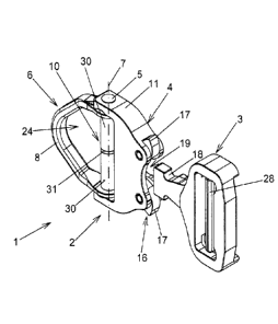
Figure 1 shows an isometric view of a belt buckle 1 according to the
invention. It is easy
to see the buckle part 2 according to the invention and the other buckle part
3, said buckle parts 2,
3 being shown in Fig. 1 in an arrangement where they are not connected
together. The other
buckle part 3 comprises a plug-in projection 18, the other buckle part 3 being
a male buckle part.
The buckle part 2 according to the invention comprises a plug-in projection
receiver 19 as the
connecting part 4 and consequently forms a female buckle part. This
arrangement is not
compulsory. It is possible in an equally good manner for the other buckle part
3 to comprise a
plug-in projection receiver 19 and the buckle part 2 according to the
invention to comprise a
plug-in projection 18. Connecting parts which are completely different can
also be provided,
such as, for example, hooks and hooks or hooks and eyes.
The buckle part 2 is consequently part of a belt buckle 1 with at least one
connecting part
4 which is realized as a plug-in projection receiver for releasably connecting
the buckle part 2 to
- 7a -
Date Recue/Date Received 2020-04-30
CA 02847952 2014-03-31
the other buckle part 3 of the belt buckle 1, and comprises a bar 5 for
fastening a belt on the bar 5
of the buckle part 2, the buckle part 2 additionally comprising a clevis type
eyelet 6 for attaching
a karabiner hook into the clevis type eyelet 6. In said exemplary embodiment,
the bar 5 is part of
the clevis type eyelet, but, as already stated, this does not have to be the
case.
As can also be seen in Fig. 1, the buckle part 2 comprises a basic body 11
which, in this
case, once again comprises the connecting part 4, which is female in said
exemplary embodiment,
for releasably connecting the buckle part 2 to the other buckle part 3 of the
belt buckle 1. The bar
shown in Fig. 1 serves for fastening the belt 26 on the buckle part 2. As
already mentioned, the
belt 26 can also be a strap or a rope or similar. The belt 26, as also the
other belt 27 which is
fastened on the other buckle part 3, is only shown in Fig. 3 and is only shown
there by a broken
line. The fastening of the belt 26 on the bar 5 and also the fastening of the
other belt 27 on the
other bar 28 of the other buckle part 3 can be effected in all manners that
are known per se. Both
bars 5 and 28 can be realized as fixed bars or as clamping bars which are
displaceable relatively
to the respective basic body or also to other bars of the respective buckle
part 2, 3. The bar 5, in
this case, is guided through two opposite holes 29 of the basic body 11 of the
buckle part 2 and is
plastically deformed in the end regions of the bar 5 lying outside in each
case in order to prevent
the bar 5 from falling out. The bar 5 can naturally also be fastened in
another manner on the
basic body 11, or can even also be a fixed part of the basic body 11. It is
also conceivable and
possible to realize the bar 5 as a screw-type element, such as, for example, a
screw, it being
possible for one of the two opposite holes 29 of the basic body 11 to be
realized as a threaded
bore. In this connection, it is naturally also possible for the bar 5 which is
realized as a screw-
type element to penetrate the two opposite holes 29 of the basic body 11 and
to be secured by
way of at least one nut. In order to prevent the screw-type connection being
unintentionally
released, reference is made to common nut and screw retaining elements and/or
materials that are
known per se. The bar 5, the multiple-part sleeve 10 and the leg 8 form the
clevis type eyelet 6 in
this exemplary embodiment.
In this exemplary design, it is provided that the clevis type eyelet 6 is
fastened on the
remaining buckle part 2 or the basic body 11 thereof so as to be pivotable
about a pivot axis 7. It
- 8 -
2961966-1
CA 02847952 2014-03-31
is consequently provided that the clevis type eyelet 6 is able to rotate or
pivot with reference to
the remaining buckle part 2, it being possible to pivot relatively between the
bar 5 and the basic
body 11, and/or between the bar 5 and the leg 8 and/or the between the leg 8
and the multiple-
part sleeve 10 and/or between the bar 5 and the multiple part sleeve 10. In
principle, it would
also be conceivable and possible for the clevis type eyelet 6 to be connected
to the remaining
buckle part 2 in particular in a rotationally fixed manner and/or to be
realized separately from the
bar 5 and/or the sleeve 10. In particular in the case of a design of the
clevis type eyelet 6 where it
is rotationally fixed in relation to the remaining buckle part 2 or the basic
body 11 thereof, it is
conceivable and possible for the at least one clevis type eyelet 6 and the
remaining buckle part 2
or the basic body 11 thereof to be realized integrally or in one piece.
In the exemplary embodiment shown, the buckle part 2 also additionally
comprises the
latching device 16 for latching the two buckle parts 2, 3 together. More
details of the function of
the latching device 16 will be given further below.
It is also easy to see in Fig. 1 that the pivot axis 7, about which the clevis
type eyelet is
pivotable, is arranged coaxially with respect to the bar 5. This is not
compulsory; however, as a
result of said arrangement advantages are produced with regard to a compact
design of the
buckle part according to the invention. It is conceivable and possible in an
equally good manner
for the leg 8 to be aligned, or arranged independently of the bar 5, at
another position with the
remaining buckle part, and in particular the pivot axis 7.
Fig. 2 shows a partially exploded drawing of a belt buckle 1 according to the
invention.
The buckle part 2 is now connected to the other buckle part 3 and latched
thereto. The design of
the exemplary embodiment of a clevis type eyelet 6 which is realized in this
case can be seen
particularly well in Fig. 2. As already mentioned, for fastening the belt 26
to the basic body 11
the bar 5 is fixedly connected with regard to its position. This is naturally
not compulsory as the
bar 5, as mentioned above, could be a displaceable clamping bar. It can also
be easily seen that
the bar 5 forms the clevis type eyelet 6 with the leg 8 of the clevis type
eyelet 6 by the bar 5
being guided through holes 9 in the leg 8. The holes 9 are situated on the
opposite sides, in this
-9-
2961966-1
CA 02847952 2014-03-31
,
,
case end regions, of the leg 8. It can easily be seen that the pivot axis 7
shown is arranged
coaxially with respect to the bar 5 in said exemplary embodiment. Fig. 2 also
shows the design
of the sleeve 10 which, in this case, is realized in multiple parts. In the
exemplary embodiment
shown, the sleeve 10 comprises two portions 30 which are substantially rigid
per se and an
elastic ring 31 lying in between them. As one unit, the sleeve 10 assumes its
function, already
mentioned in the introduction, of supporting the two ends of the bent leg 8 in
the event of high
tensile loads on the clevis type eyelet 6. In said exemplary embodiment, the
elastic ring 31 serves
for the described preloading and ensures, as explained again below, that the
leg 8 and
consequently the clevis type eyelet 6 latch-in in the pivot positions in which
this is provided. In
addition, the elastic ring 31 also serves for preventing gaps which sometimes
occur between the
portions 30 of the sleeve 10 and/or between the leg 8 and the sleeve 10 during
pivoting or in the
pivot positions of the clevis type eyelet. These gaps can otherwise result in
ingress of dirt or dust
or even in the belt 26 jamming or hooking on the bar 5 or the sleeve 10. This
can then
subsequently result in damage to the belt 26, or can impair the adjustability
of the belt 26. To
complete the picture, it must be mentioned that this naturally also applies to
an integral, elastic
design of the sleeve. It is pointed out that the sleeve 10 can comprise all
but also only part of the
named functions. For example, the preloading function of the sleeve 10 can be
omitted if the
preloading is applied by the leg 8 itself or by the basic body 11.
Looking at the assembled state of the buckle part 2 in Fig. 1 and the exploded
drawing in
Fig. 2, it is easily comprehensible that the bar 5 in the exemplary embodiment
is guided through
the multiple-part sleeve 10 and the sleeve 10 is arranged between the regions
of the leg 8
comprising the holes and supports the regions of the leg 8 comprising the
holes 9 or preloads
them in the direction 25 away from one another. In this case, it is possible
for the sleeve 10 to be
realized completely or in regions in an elastic manner, where applicable also
in an integral
manner. The sleeve 10 is a preferably tubular body, through which the bar 5 is
guided. Fig. 2
shows the directions 25 in which the sleeve 10 acts on the leg 8 for
supporting and/or preloading.
The sleeve 10, in this case, along with the job of preloading the leg 8, also
has the supporting
function where it is a question of ensuring the geometry of the leg 8 even
when large tensile
loads act on it. It is easy to imagine that a tensile load produced by a
karabiner which is hooked
- 10 -
2981966-1
CA 02847952 2014-03-31
in the clevis type eyelet 6 could result in a reduction in the spacing between
the regions of the leg
comprising the holes 9 depending on the effective direction. The sleeve 10
prevents this by
preventing the leg 8 possibly deforming elastically or plastically and
consequently permanently
in the region of the bar 5. In said exemplary embodiment, the clevis type
eyelet 6 comprises an
elevation 13 in the region of the leg 8, the function of which elevation is
explained further below.
Fig. 3 and Fig. 4 show views of a belt buckle 1 according to the invention
with the buckle
parts 2 and 3 in the connected and latched state. It can seen particularly
well that the clevis type
eyelet 6 of the buckle part 2 includes in a circumferentially closed manner an
opening 24 for
attaching the karabiner hook, an imaginary circle 23 inscribed in said opening
24 in a favorable
manner comprising a minimum radius 22 of at least 5 mm, preferably of at least
7 mm. In said
exemplary embodiment, the opening 24 is defined by the sleeve 10 and the leg
8.
Fig. 4 shows a side view of the belt buckle 1 according to the invention and
the line of
intersection C-C. In order to show in a better manner the functionalities of
the buckle part 2 and
of the latching device 16 as well as the connection to the other buckle part
3, as is realized in the
variant shown here, the section along the line of intersection C-C is shown in
Fig. 5. It can also
easily be seen here that the bar 5 is connected in a positive locking manner
to the basic body 11.
It can also easily be seen in the sectioned representation in Fig. 5 that the
leg 8 and the bar 5 or
the sleeve 10 border the opening 24 in a circumferentially closed manner.
The connecting part 4 of the buckle part 2 is realized, in this case, as a
female plug-in
projection receiver 19. The buckle part 2 is consequently a female buckle
part. In this exemplary
embodiment, the buckle part 2 additionally comprises a latching device 16, the
buckle parts 2, 3
latching into one another when connecting together by means of said latching
device 16 and the
latching elements 17, realized in this case as a latching lever, of the
latching device 16 having to
be actuated, preferably by hand, for releasing the buckle parts 2, 3 from one
another. In order to
secure the latching-in of the latching element 17, springs 20 are built in the
latching device 16.
Said springs 20 can be metal helical springs, but also elastomer springs or
other suitable spring
elements or spring materials. It is easily comprehensible that when inserting
the plug-in
- 11 -
2961966-1
CA 02847952 2014-03-31
projection 18 into the plug-in projection receiver 19, the latching elements
17 are pivoted about
the pivot axis of the bolts 21 and the springs 20 are compressed as soon as
the T-shaped plug-in
projection 18 slips along the latching elements 17. When moved further closer
together, the
undercut of the T-shaped region of the plug-in projection 18 passes the
latching elements 17, as a
result of which the latching elements 17 latch in the undercut under the
influence of the spring-
preloading of the springs 20 and consequently secure a positive locking
connection between the
buckle parts 2 and 3. In said exemplary embodiment, it is provided that the
latching elements 17
have to be moved by hand, as a result of a targeted actuation, in order to
release the T-shaped
plug-in projection 18 or the undercut thereof and to release the positive
locking connection
between the buckle parts 2, 3 again in order to be able to separate said
buckle parts from one
another.
In general, it must be stressed that all the components of the belt buckle 1
can be formed
of metal, metal alloys or other suitable materials or can comprise said
materials at least in part. It
is conceivable and possible, in particular, for the named parts also to be
able to consist at least in
part of plastics material, in particular fiber-reinforced plastics material.
The sleeve 10 can be
formed of at least in part of an elastomer, for example rubber or a metal
spring element. In
particular rubber/metal elements but also plastics materials, fiber-reinforced
plastics materials
and also two-component plastics materials are conceivable and possible.
It is pointed out once again at this point that the latching device 16 can
also be part of the
other buckle part 3, that is in particular of a male buckle part. In this
case, it is not compulsory
for the preloading of the latching element 17 to be realized by a spring 20.
Rather, it is also
conceivable and possible to develop the latching element 17 itself as a
resilient element and/or to
realize it integrally with the plug-in projection 18 or the plug-in projection
receiver 19.
The realizing of the pivot positions of the buckle part 2 according to the
invention is now
shown by way of Fig. 6 to 12. In one or a few of the possible pivot positions
the clevis type
eyelet 6 can latch onto the remaining buckle part 2 or the basic body 11. In
the exemplary
embodiment, the basic body 11 has several indentations 12 for this purpose.
- 12 -
2981968-1
CA 02847952 2014-03-31
The arrangement of said indentations 12 in the case of the exemplary
embodiment shown
in this case can be seen particularly well in Fig. 7. The leg 8 comprises, as
can be seen in Fig. 2,
at least one elevation 13 which is able to latch into the corresponding
indentation 12.
Consequently, it is possible for the clevis type eyelet 6 to latch into
individual or several
preferred pivot positions. When adjusting from one pivot position into the
other pivot position, a
certain torsional resistance has to be overcome. The elevation 13 has to be
pivoted out of the
indentation 12 for this purpose, the elevation 13 slipping along the
indentation. This
subsequently leads to the leg 8 deforming elastically. The preloading required
for this purpose in
the directions 25 is provided in the exemplary embodiment shown in part by the
leg 8 itself, but
also in part by the sleeve 10 or the elastic ring 31 thereof. In other words,
it is consequently
possible to deform the sleeve 10 in its longitudinal extension and thereby to
enable the transition
from one pivot position to the other pivot position of the clevis type eyelet
6. When the clevis
type eyelet 6 reaches the next pivot position, the elevation 13 of the clevis
type eyelet 6 latches
in the indentation 12 and the sleeve 10, or the ring 31 relaxes again in a
corresponding manner.
Fig. 9 to 12 show the two pivot positions of the exemplary embodiment in which
latching-in
occurs. The clevis type eyelet 6 can naturally be pivoted in relation to the
remaining buckle part
2 in any arbitrary position lying between the two latched-in pivot positions
and also beyond both
pivot positions and can be positioned on the basic body 11 without latching-
in. As already
mentioned, it is also possible to arrange the elevations 13 on the basic body
11 and the
corresponding indentations 12 on the leg 8.
- 13 -
2961966-1
CA 02847952 2014-03-31
,
Key to the Reference Numerals:
1 Belt buckle 29 Hole
2 Buckle part 30 Portion
3 Other buckle part 31 Elastic ring
4 Connecting part
Bar
6 Clevis type eyelet
7 Pivot axis
8 Leg
9 Hole
Sleeve
11 Basic body
12 Indentation
13 Elevation
16 Latching device
17 Latching element
18 Plug-in projection
19 Plug-in projection receiver
Spring
21 Bolt
22 Radius
23 Circle
24 Opening
Direction
26 Belt
27 Belt
28 Other bar
-14-
2961966-1