Note: Descriptions are shown in the official language in which they were submitted.
N-DOPED CARBON MATERIALS
TECHNICAL FIELD
[000 1 ] Carbon materials.
BACKGROUND
[0002] Nitrogen - rich carbon materials are very useful for applications
such as
supercapacitors, battery electrodes, oxygen reduction reaction supports for
polymer
electrolyte membrane (PEM) fuel cells and direct methanol fuel cells, and as
sorbents for
CO2 capture. They are also very useful as supports for other "active"
materials such as
Fe304, which yields synergistic CO2 capture and heavy metal absorption
performance.
[0003] Unfortunately nitrogen - rich carbonized materials are expensive
to
manufacture, normally requiring intense chemical treatments, such as acid
boiling or
exposure to high temperature ammonia vapors, in order to make their surfaces
rich in
nitrogen atoms. Moreover since these atoms are only at the outermost surface
layer, the
nitrogen-induced functionality wears out with prolonged use. Ideally the high
(near 10%
by weight) content would be in the bulk of the carbonaceous material, rather
than at the
surface. This would require high nitrogen content in the feedstock. A major
economic
advantage of such feedstock is that it would not require additional chemical
treatments
but would rely simply on pyrolysis and activation. Many such materials come
from
esoteric sources such as certain forms of seaweed.
[0004] Others have soaked eggshell membrane (ESM) in Co(NO3)2 = 6H20 and
have pyrolyzed the whole structure. Also. ESM is often used as a template for
other
structures and is removed during pyrolysis.
1
CA 2848104 2019-02-05
W020131033847 CA 02848104 2014-03-07
PCT/CA2012/050623
SUMMARY
[0005] In an embodiment, there is disclosed a carbon material comprising
pyrolized
egg protein characterized by containing mesopores or micropores. The pyrolized
egg protein
may comprise pyrolyzed eggshell membrane having a continuous conducting core
and a
porous shell, the pyrolyzed eggshell membrane comprising partially-activated
carbon. The
porous shell may comprise nitrogen or oxygen. The pyrolized egg protein may
comprise
mesoporous egg white. The carbon material may be functionalized by addition of
elemental
materials, alloys, oxides, nitrides, sulfides, hydrides, or hydroxides.
[0006] In an embodiment, a method of forming a capacitive material is
disclosed
comprising pyrolyzing eggshell membrane and partially activating carbon in the
eggshell
membrane to yield a partially-activated eggshell membrane having a continuous
conducting
core and a porous shell. The pyrolyzed eggshell membrane may be
functionalized. The
porous shell may comprise nitrogen or oxygen.
[0007] In an embodiment, there is disclosed a capacitive material,
comprising
pyrolyzed eggshell membrane having a continuous conducting core and a porous
shell, the
pyrolyzed eggshell membrane comprising partially-activated carbon. The porous
shell may
comprise nitrogen or oxygen. The carbon material may be functionalized by
addition of
elemental materials, alloys, oxides, nitrides, sulfides, hydrides, or
hydroxides.
[0008] In an embodiment, there is disclosed a method of forming a carbon
material,
comprising adsorbing proteins onto a porous template and pyrolizing the
proteins on the
porous template to form activated carbon. The proteins may comprise egg white
proteins.
The porous template may be mesoporous. The method may comprise removing the
porous
template after pyrolizing. The method may comprise functionalizing the
activated carbon.
The activated carbon may contain nitrogen.
BRIEF DESCRIPTION OF THE FIGURES
[0009] Embodiments will now be described with reference to the figures, in
which
like reference characters denote like elements, by way of example, and in
which:
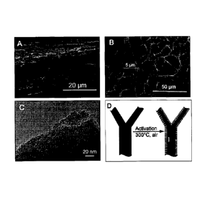
[0010] Fig. 1 shows SEM images of activated CESM in cross-section view (A)
and
plan view (B), the inset of (B) is the high resolution image of the selected
area; (C) TEM
2
WO 2013/033847 CA 02848104 2014-03-07
PCT/CA2012/050623
image of activated CESM; (D) Illustration of the carbon-carbon core-shell
structure of
activated CESM.
[0011] Fig. 2 shows electrochemical performance of eggshell membrane
derived
carbons in three-electrode system. Cyclic voltammograms in 1M KOH (A) and in
1M H2SO4
(B); galvanostatic charge/discharge curves at 0.5A g-1 (C); gravimetric
capacitances
measured at various charge/discharge current density (D); the evaluation of
specific
capacitance versus the number of cycling at 4A g-1 (E); Nyquist plots in 1M
H2SO4 (F). A
and B: at -0.4 (A) and 0.4 (B) along the X-axis, the curves from top to bottom
are: CESM-
300, AC-KOH, CESM-AP, CESM-AP, AC-KOH, and CESM-300. C: upper graph - curve
with leftmost peak is AC-KOH, next is CESM-300, lower graph ¨ curve with
leftmost peak
is AC-KOH, next is CESM-300. D: curves from top to bottom are CESM-300 (1M
KOH),
CESM-300 (1M H2SO4), AC-KOH (1M KOH), AC-KOH (1M H2SO4). E: both graphs¨
top curve is CESM-300 (in 1M KOH), bottom curve is CESM-300 (in 1M H2SO4). F.
both
graphs ¨ left curve is CESM-300, right curve is AC-KOH.
[0012] Fig. 3 shows (A,B) SEM micrographs and (C, D) TEM micrographs of the
mesoporous cellular foam silica template used for the template for the egg
white.
[0013] Fig 4 is (A) low magnification SEM micrograph of MPEw-850; (B) and
C)
Low and high resolution TEM micrographs of MPEw-850. The carbon TEM grid
support is
visible in (E), while arrows point to different size pores in (F)
[0014] Fig. 5 is (A,B) and (C,D) TEM micrographs of MPEw-750 and MPEw-650,
respectively.
[0015] Fig. 6 shows Electrochemical performance of MPEw carbons tested in a
LIB
half-cell configuration. (A) Cyclic voltammograms of MPEw-650, tested at 0.1
mV/s; (B)
charge/discharge curves of MPEw-650, tested at 0.1 A g-1; (C) charge/discharge
capacity
versus cycle number for the three carbons. A: lower curve is 1st, upper curve
is 2"d and 31
overlying each other, B: charge graph ¨ curves from top to bottom are 100th,
101h, 2nd, 1s1
,
discharge graph ¨ curves from top to bottom are et, 2nd,
10-, 100th, C: between 0-20 and 90-
100 on the x-axis - curves from top to bottom are MPE-650, MPE-750, MPE-850,
between
20-70 on the x-axis ¨ curves from top to bottom are MPE-650, MPE-850, MPE-750,
between 70-80 on the x-axis ¨ top curve is MPE-850 overlying MPE-650, bottom
curve is
3
WO 2013/033847 CA 02848104 2014-03-07
PCT/CA2012/050623
MPE-750, between 80-90 on the x-axis ¨ curves from bottom to top are MPE-850,
MPE-
650, MPE-750.
[0016] Fig. 7 is LIB half-cell tests of MPEw. (A) and (B) Charge/discharge
curves of
MPE-750 and of MPE-850, tested at 0.1 A Si.; (C) cycling coulombic efficiency
of the three
carbons at various charge/discharge rates; (D) capacity versus cycle number of
the three
carbons, tested at 0.5A g-1. A: charge graph ¨ curves from top to bottom are
100th, 10th, 2nd,
14, discharge graph ¨ curves from top to bottom are 1st, 2"4, 10th, 100th, B:
charge graph ¨
curves from top to bottom are 100th, 10t1
, 2nd et, discharge graph ¨ curves from top to
bottom are 1st, 2nd, 10th
100th, C: MPE-750, MPE-850, MPE-650 curves overlie each other,
on the left side of the graph MPE-750 is slightly above and MPE-650 is
slightly below MPE-
850, D: curves from top to bottom are MPE-650, MPE-850, MPE-750.
DETAILED DESCRIPTION
[0017] In one embodiment, there is disclosed pyrolized egg protein
characterized by
containing mesopores (average pore size 2nm-50nm) and micropores (pore size
less than 2
nm) or both. In an embodiment, there is disclosed pyrolized egg protein
comprising
partially-activated, pyrolyzed (carbonized) eggshell membrane. The partially-
activated,
pyrolyzed eggshell membrane described herein may be an intact, stand-alone
membrane.
[0018] There is also disclosed a nitrogen-rich, highly graphitic, fibrous
material, in
which the shell (outer region) of the fibres is porous but the core is solid,
and a method of
producing the material from an eggshell membrane.
[0019] There is also disclosed a process for converting eggshell membranes
and egg
whites to value-added nitrogen-rich carbons. Eggshell membranes and egg
whites, which are
naturally rich in nitrogen, constitute a waste product in many operations such
as commercial
egg production, for example, eggs that are pre-cracked or did not pass
inspection otherwise
In an embodiment, the eggshell membrane is heated up in an inert atmosphere
for pyrolysis.
After pyrolysis, the eggshell membrane may be cleaned, for example, using KOH
and HCl,
and is partially activated to increase the surface area (in the outer "shell")
and to incorporate
oxygen. In the preferred embodiment, the nitrogen content and interconnected
fibrous
structure of the eggshell membrane remain largely intact after treatment, and
the treated
4
W02013/033847 CA 02848104 2014-03-07
PCT/CA2012/050623
eggshell membrane is a capacitive material with a continuous conducting core
and a porous
shell. The nitrogen-rich (through the bulk) product is suited for
supercapacitors, battery
electrodes, CO2 capture, oxygen reduction reaction, catalysis, macromolecule
sorption, and
environmental remediation, such as heavy metal capture, hydrocarbon
absorption, and
chemical spill sorption. In the case of egg whites, egg white protein may be
adsorbed onto a
mesoporous or microporous template and pyrolized to form activated carbon. The
mesoporous or microporous template may then be removed, leaving a stand alone
structure,
or a structure that may be placed on a support for further use, such as for
for supercapacitors,
battery electrodes, CO2 capture, oxygen reduction reaction, catalysis,
macromolecule
sorption, and environmental remediation, such as heavy metal capture,
hydrocarbon
absorption, and chemical spill sorption.
[0020] Full activation would excessively decrease the nitrogen content and
make the
core too porous, leading to poor electrical conductivity as the equivalent
series resistance
increases and the power density drops. Conversely, partial activation
increases the surface
area within the outside "shell" of the fibres by removing the amorphous
carbon, while
retaining the nitrogen atoms and the solid cores of the fibres, both of which
are needed for
high electrical conductivity. Activation further adds oxygen. Both nitrogen
and oxygen
contribute to faradaic capacitance and high electrical conductivity. It is
believed that what
happens during pyrolysis in inert atmosphere is that the organic carbon gets
converted into
graphitic and amorphous carbon During activation in oxygen, the amorphous
carbon gets
burned away so that it is mainly graphitic carbon that remains. Performing all
the pyrolysis
in oxygen would just burn everything away.
[0021] In an alternative embodiment, the eggshell membrane may be partially
activated through a single heating schedule instead of separate heating
schedules for both
pyrolysis and activation. For example, the eggshell membrane could be
pyrolyzed in inert
atmosphere, with oxygen added at the end for the partial activation. However,
it is
preferable to bring the temperature back down after pyrolysis and to clean the
membrane in
KOH and HCl as this gets rid of inorganic impurities, which can affect the
electrochemical
measurements (e.g., the electrochemical performance in KOH is already greatly
stabilized
after this cleaning step).
WO 2013/033847
PCT/CA2012/050623
CA 02848104 2014-03-07
[0022] In this patent document is also disclosed a nitrogen-rich, highly
graphitic
material, in which the shell (outer region) is porous but the core is solid,
and a method of
producing the material from egg white.
[0023] In an embodiment mesoporous carbon derived from egg white (MPEw) is
synthesized from egg white using a mesoporous template containing pores with
diameters
between 2 and 50 nm, or an activation treatment to make the egg white porous.
The utility of
mesoporous and microporous activated carbon depends for example on the
application
(super capacitor vs. battery), electrolyte (aqueous vs. polymer) and scan
rate. In general
small microporosity is useful for aqueous supercapacitor electrolytes and at
lower scan rates.
At higher scan rates and in polymer electrolytes (almost always the case for
LIB batteries)
small mesopores are better. Too many large mesopores result in a low surface
area, which is
generally undesirable, but some large mesopores are useful for electrolyte
transfer. Very
small micropores (<1 nm or so) tend not to be very useful for most
applications since even in
aqueous electrolytes they give transport problems at higher scan rates. For
use as a
supercapacitor or as an electrode in a battery, the structured carbon
materials are typically
combined with binder and carbon black in conventional manner.
[0024] The proteins present in the egg white are adsorbed into the template
and
subsequently pyrolyzed under inert atmosphere. In an embodiment the pyrolyzed
egg white
is a capacitive material with a continuous conducting carbon core and a porous
shell with
nitrogens and oxygen. The nitrogen-rich (through the bulk) product is suited
for
supercapacitors, battery electrodes, CO2 capture, oxygen reduction reaction,
catalysis,
macromolecule sorption, and environmental remediation, such as heavy metal
capture,
hydrocarbon absorption, and chemical spill sorption.
[0025] In an alternative embodiment, the pyrolyzed egg white may not be
activated.
[0026] Other methods to partially activate the pyrolyzed eggshell membrane
or
pyrolyzed egg white may be used, such as using CO2, CO, or steam, instead of
oxygen.
Chemical activation techniques may also be used in certain embodiments, and
may involve
soaking the membrane in acid, base, or salt, and then heating the membrane in
a single
pyrolysis/activation step.
6
W02013/033847 CA 02848104 2014-03-07
PCT/CA2012/050623
[0027] The pyrolyzed carbon may be functionalized, in respective
embodiments,
with oxides or hydroxides of elements such as iron (e.g., Fe304, Fe2O3,
Fe0OH),
manganese (e.g., Mn02), cobalt (e.g., Co304, Co02), ruthenium, vanadium, or
nickel; or
with nitrides such as VN or TixV1-xN; or with hydrides such as MgH2; or with
sulfur or
sulfides such as FeS; or with elemental materials such as platinum (Pt),
aluminum (Al),
silicon (Si), or tin (Sn), or with alloys of the preceding elements; or with
oxides such as
cobaltites (e.g., NiCo204) and molybdates (e.g, CoMo04, NiMo04, FeMo04,
MgMo04,
MnMo04); or combinations of those materials to further its applicability to
applications such
as battery electrodes, oxygen reduction reaction supports, and use in
supercapacitors and
sorbents for the capture of CO2, organic carbon, naphthenic acid and heavy
metals. The
preceding list is not intended to be limiting, as other materials may also be
used for these or
other applications.
[0028] Oxides may be added to the pyrolized carbon, such as eggshell
membrane or
egg white, for example, by reactive sputtering or by soaking the membrane in
an appropriate
solution and heating it up. Metals may be applied to the pyrolized carbons,
such as eggshell
membrane or egg white, for example, by sputtering. Nitrides may be added, for
example, by
reactive sputtering. Other methods of coating (functionalizing) the membrane
or egg white
with various materials include, for example, physical vapor deposition;
chemical vapor
deposition; electrodeposition; and wet chemical methods, such as sol-gel
synthesis,
hydrothermal processing, precipitation, and ionothermal processing.
[0029] Example: The eggs used in the experiments are produced at Sparks egg
farm
in Calgary. To keep the most consistence, only the eggs weighting between 56 g
to 60 g are
used. The eggshell membranes are obtained by etching away the hard eggshell
(mainly
CaCO3) in 1M HC1. After cleaning with DI water, the eggshell membrane is put
on a 1 cm2
glassy carbon disc, dried and carbonized at 800 C for 2 hours in a tubular
furnace with argon
flow of 100 mL min-1. The heating rate is 1 C min-1. After the carbonization,
the eggshell
membrane converts to a uniform carbon film strongly bonded on the surface of
carbon disc
The carbonized eggshell membrane (CESM) supported on carbon disc is washed in
20%
KOH at 70 C for 2 hours and then in 2M HC1 for 15 hours at room temperature to
remove
the impurities. The CESM supported on carbon disc is activated at 300 C for 2
hours in air at
7
WO 2013/033847 CA 02848104 2014-03-07
PCT/CA2012/050623
a heating rate of 10 C min-1. During the activation process, 10% weight loss
is detected.
The chemically activated eggshell membrane (AC-KOH) is prepared by heating the
mixture
of dry eggshell membrane and KOH (1:4 by weight) to 700 C for 2 hours under
argon
atmosphere. The obtained fine carbon powder is washed with 2M HC1 and DI water
before
use.
[0030] The carbon disc with activated CESM is sealed in a Teflon electrode
assembly using epoxy resin and directly used as electrode without any binder
between
CESM and glassy carbon disc. For AC-KOH materials, the slurry of 95% AC-KOH
and 5 %
PVDF (binder) in N-methylpyrrolidone solvent is coated on glassy carbon disc
and then
dried at 110 C overnight in vacuum oven to obtain the electrode. The
electrochemical
experiments are performed in Teflon beakers with Pt wire as counter
electrodes. Hg/Hg0
(1M NaOH) and Hg/fIgSO4 (saturated K2SO4) are used as reference electrodes
individually
in 1M KOH or 1M H2SO4. For convenience, all the potentials discussed in this
paper have
been converted to potential versus normal hydrogen electrode (NHE). The Cyclic
voltammetry and galvanostatic charge-discharge cycling and impedance analysis
are
performed on a Solatron 1470E Multichannel Potentiostat/CellTest System. The
specific
capacitance of CESM is calculated as ItimAE, where 1 is the change/discharge
current, t is
the discharging time, m is the mass of electrode materials and .6,E stands for
the potential
window.
100311 For the surface area analysis, eggshell membrane is also carbonized
on Si
wafer under the same condition. In this case, the CESM film can be peeled off
from Si wafer
after the treatment in 20% KOH. We believe the surface area of obtained CESM
films is a
good estimation of the CESM carbonized on glassy carbon disc. The porous
texture of
carbon materials is characterized by nitrogen adsorption at 77k (Quantachrome
Autosorb-1).
A Hitachi S-4800 scanning electron microscope (SEM) equipped with field
emission gun
and a JEOL 2100 transmission electron microscopes (TEM) are used to study the
morphologies of CESM. X-ray photoelectron spectroscopy (XPS) is obtained on an
Axis
Ultra spectrometer. The element analysis are performed on Thermo Fisher
Scientific
(formerly Carlo Erba) EA 1108 CHNS-0 elemental analyzer and Perkin Elmer 's
Elan 6000
for metals. Before XPS and element analysis, the samples were dried at 110 C
in vacuum
8
W02013/033847
PCT/CA2012/050623
CA 02848104 2014-03-07
oven over night to remove the absorbed water. The conductivity of CESM is
measured by
Pro4 from Lucas Labs.
[0032] Chicken eggshell membrane has around 12%-15% N in its organic
matter.
After carbonization, the N content in as-prepared CESM is around 8% by the
combustion
element analysis shown in Table 1 below. In fact, the eggshell membranes are
mainly
proteins (rich in N) with very small amount of carbohydrates (no N). It is not
surprising that
CESM contains more N than chars from biomaterials rich in cellulose and lignin
(for
example, woods). The N atoms would contribute to the good conductivity of CESM
since
the electrical conductivity of N-containing carbons is known to be normally
higher than that
of N-free carbons. When further activated, the CESM-300 keeps similar N
content.
However, the chemically activated eggshell membrane (AC-KOH) contains only
1.3% N
indicating most of N functional groups are destroyed in the chemical
activation process. The
0 content in as-prepared CESM is 9.4% which increases to 10.67% after the
further
activation. AC-KOH contains slightly more 0 than CESM-300 but the atomic ratio
between
0 and C (0/C) is almost same for both samples. XPS is also used identify the
content of N
and 0. It is interesting to compare the atomic N/C and 0/C ratios obtained by
combustion
element analysis to those by XPS since XPS provides the information at the top
layers (1-10
nm) of surface. The N/C ratios obtained by both technologies are relatively
consistent in all
samples. However, the 0/C ratio obtained by XPS is significant higher than
that from
combustion element analysis in activated CESM. The differences of 0.0285 in
0/C ratio
indicate the oxygen content on surface is 1.25 times of that in bulk materials
in CESM-300.
This is important for the application of supercapacitors since only the oxygen
on surface has
contribution to pseudocapacitance. It can also be concluded that the 0 content
on surface
increase 30.1% while the 0 content in bulk materials increase only 14% during
the activation
process in hot air. That clearly indicates the activation (oxidation) of CESM
only happens on
the surface of carbon fibers and the cores of the carbon fibers are unlikely
activated or at
least not fully activated. Besides C, N, and 0, activated CESM also contains
around 3-5%
other impurities (mainly Si, Ca, K, Cl, see ICP trace metal analysis in Table
2 below).
[0033] Table 1. Elements composition information of eggshell membrane
derived
carbons.
9
WO 2013/033847
PCT/CA2012/050623
CA 02848104 2014-03-07
Element analysis XPS
C wt% 0 wt% N wt% 0/C [a] N/C Ea" 0/C ibl N/C rbl
CESM-AP 77.51 9.72 8.15 0.0941 0.0901 0.1013 0.0942
CESM-300 76.52 10.99 8.48 0.1077 0.0951 0.1362 0.0921
AC-KOH 81.93 12.26 1.31 0.1123 0.0137 0.1202 0.0147
[a] Atomic ratio from combustion element analysis. [b] atomic ratio from XPS
[0034] Table 2. The
contents of metals in activated CESM by trace metal analysis.
Metal Li Be B Na Mg Al Si
DLFal (ppm) 0.05 0.1 2 0.5 2 0,2 5 5
Content (ppm) 4.41 <DL <DL 1146 249 236 421 1236
Metal K Ca Ti V Cr Fe Mn Co
DL [al (ppm) 6 31 0.09 0.05 0.05 3.7 0.03 0.03
Content (ppm) 10705 10179 28.0 <DL 55.5 518 9.94 23.1
Metal Ni Cu Zn Ga Ge As Se Rb
DL[a] (ppm) 0.06 0.03 0.08 0.01 0.02 0.06 0.2 0.04
Content (ppm) 68.6 537 890 0.02 0.09 25.1 <DL 12.5
Metal Sr Y Zr Nb Mo Ru Pd Ag
DLrai (ppm) 0.03 0.02 0.09 0.04 0.02 0.01 0.01 0.01
Content (ppm) 10.7 0.23 10.1 2.61 89.2 0.23 6.35 5.28
Metal Cd Sn Sb Te Cs Ba La Ce
DL[a] (ppm) 0.06 0.06 0.01 0.02 0.02 0.03 0.03 0.03
Content (ppm) 0.22 5.46 0.63 0.43 <DL 5.94 .. 0.57 .. 1.76
Metal Pr Nd Sm Eu Gd Tb Dy Ho
DLEal (ppm) 0.004 0.03 0.04 0.03 0.03 0.03 0.04 0.02
Content (ppm) 0.037 0.14 <DL <DL <DL <DL <DL <DL
Metal Er Tm Yb Lu Hf Ta W Re
WO 2013/033847
PCT/CA2012/050623
CA 02848104 2014-03-07
DLIal (ppm) 0.04 0.006 0.05 0.04 0.05 0.02 0.08 0.003
Content (ppm) <DL <DL <DL <DL 0.83 9.37 1.90 0.046
Metal Os Ir Pt Au Ti Pb Th U
DLEal (ppm) 0.08 0.04 0.01 0.01 0.05 0.03 0.01
0,03
Content (ppm) 0.14 <DL 1.67 2.19 0.06 21.2 0.16
0.06
[a] detection limits of the equipment.
[0035] The surface N functionalities are identified by the deconvolution of
high-
resolution N is core level peaks The N is core level is fitted using CasaXPS
software by 4
peaks representing pyridinic N (N-6 at 398.00.2 eV), pyrrolic or pyridonic N
(N-5 at
399.7 0.2 eV), quaternary N (N-Q at 400.80.2 eV) and oxidized N (N-X at
402.50.2 eV).
The percentage of each component is shown in Table 3 below. It is interesting
to find that
the percentage of N-6 decreased from 39.88% to 20.83% while the percentage of
N-5
increased from 25.74% to 47.49% after the activation process in air. That
indicates around
half of pyridinic N converted into pyrrolic N or pyridonic N. We are also
interested in the N
at the edge of graphite plane (N-5, N-6, and N-X) which is known to be more
active than that
located in the middle of graphite plane (N-Q). The percentage of N on edge in
our CESM is
very high, 72.51% in CESM-AP and 76.96% in CESM-300.
[0036] Table 3. Approximate distribution of N-functional groups obtained by
fitting
the N Is core level XPS spectra.
% of total N is
Functional groups N-Q N-5 N-6 N-X
B. E. (eV) 400.8 399.7 398,0 402.5
CESM-AP -27.49 25.74 39.88 6.89
CESM-300 23.04 47.85 20.83 8.28
[0037] The surface area and pore structures characterization parameters
are
summarized in Table 4 below. For CESM materials, the specific surface area
calculated by
BET method has increased from17 m2 g-1 to 221 m2 g-1 and the average pores
size dropped
W02013/033847 CA 02848104 2014-03-07 PCT/CA2012/050623
from 8.0 nm to 1.2 nm after the activation process. The surface area from
micropores (<2nm) .
calculated by the t-plot method is 0 m2 g-1 for as-prepared CESM and 193 m2 g-
1 for
activated CESM. Obviously, mainly micropores are formed on CESM surface during
the
partially oxidation and removing of carbon in hot air which leads to the
increase of specific
surface area and porosity. However, even after activation, the specific
surface area and
porosity of CESM is only about 1/7 of those of chemically activated eggshell
membrane
(AC-KOH). That also suggests the CESM is only partially activated on the
surface.
[0038] Table 4. Physical and electrical properties of eggshell membrane
derived
carbons.
SBET Smicroki Vtotalib] APDicl Resistance C
[d]
m2/g nazig cm3/8 nm m Fig
CESM-AP 17.03 0 0.068 8.07 4.6X10⁻⁴ 120
CESM-300 221,2 193.1 0.13 1.2 8.9X10⁻⁴ 297
AC-KOH 1575 709.1 0.98 1.25 1.8X10⁻² 203
[a] surface area of micropores calculated by t-plot method. [b] Total pore
volume. [c]
Average pore diameter. [d] Capacitance at current density of 0.2 A g-1 in IM
KOH.
[0039] The microstructures of eggshell membrane directly carbonized and
activated
on glassy carbon were investigated by SEM. From the cross section view at the
edge (Fig.
1A), it can be seen that the activated CESM is a highly porous film with a
thickness of
around 10 p.m. Given the measured weight of activated CESM is 0.5 mg cm-2, its
density is
calculated to be 0.5 g cm-3, similar to activated carbons. The macroporous
network structure
composed of interwoven and coalescing carbon fibers ranging mainly from 0.2-2
p.m in
diameter can be observed in planview (Fig. 1B). Clearly the typical structure
of eggshell
membrane is successfully preserved by using our carbonization and activation
procedure.
SEM analysis revealed no difference in the microscope structures of the CESM
before and
after activation. This is expected since the pores introduced by the
activation process are
mainly micropores. The macropores between carbon fibers and the micropores on
the carbon
fibers form a hierarchical porous structure evenly distributed in activated
CESM in large
12
W02013/033847 CA 02848104 2014-03-07
PCT/CA2012/050623
scale. This kind of long-range continuity of the pore network is known to be
critical for fast
electrolytes transfer. With TEM (Fig. 1C), we can start to see the disordered
texture of
activated CESM and some pores at the edge of a thin flake. As mentioned in the
previous
discussion, the significant 0 content increase on surface and relative low
surface area and
porosity after activation indicate the activation process mainly happened on
the surface of
carbon fibers of CESM and therefore a carbon-carbon core-shell structure is
likely formed
(Fig. 1D). The activated shell containing more 0 and micropores (surface area)
is great for
the application of supercapacitors. But it also has a higher electrical
resistance due to the
micropores generated. The un-activated core can serve as electron collector.
One of the
advantages of 3D coalescing structure of CESM is that there is no contact
resistance between
fibers. Although the less conductive micropore-rich shell formed on top of
fibers during
activation, the highly conductive internal cores of fibers still coalesced
into one piece, which
makes the activated CESM an excellent conductive system. The electrical
resistance
measured by 4 point probing method is 4.6X10⁻⁴ Slm for as-prepared CESM and
8.9X10⁻⁴
Om for activated CESM. The increase of resistance is caused by the micropores
formed
during activation. They are much lower than the resistance of chemically
activated eggshell
membrane (1.8X10⁻² Sim) compacted under 20 MPa (10-100 MPa is the most common
pressure used to make carbon electrodes). For the commercial high surface area
activated
carbon, the resistance is in the range of 0.5-3.0X10⁻² i2m in compacted form.
The Raman
spectra (Fig S1) demonstrate that the CESM is composed of disordered carbon,
similar to
activated carbon. However, due to its unique structure, the systematic
conductivity of CESM
is one order magnitude higher than that of activated carbon, which makes it an
ideal
electrode material for high power density supercapacitors.
[0040] Electrochemical performance of activated CESM is evaluated in three-
electrode system (Fig. 2). The chemically activated eggshell membrane (AC-KOH)
has also
been tested as a reference. AC-KOH exhibit almost rectangular cyclic
voltammogram (CV)
in both 1M KOH (Fig. 2A) and IM H2SO4 (Fig. 2B), indicating the dominant
contribution
from EDL capacitance. The small humps at 0.5-0.6V (vs NHE) in 1M H2SO4
correspond to
pseudocapacitive contribution of quinone/hydoquinone redox processes. The
activated
CESM presents similar CV but with more developed humps in both 1M KOH and IM
13
W020131033847 CA 02848104 2014-03-07
PCT/CA2012/050623
H2SO4, suggesting big contribution from pseudocapacitance. Notably, the CV
humps of
activated CESM in 1M H2SO4 shift to 0.6-0.7V (vs NHE) indicating the
pseudocapacitive
contribution is not only from the 0 functionalities but also from the N
functionalities.
Different from the activated CESM, the as-prepared CESM shows a triangle-like
CV. The
difference may relate to the change of surface functionalities during
activation, such as the N
functionalities discussed in XPS analysis. More CVs at different sweeping rate
can be found
in Fig. S2. The reversible capacitive behavior of activated CESM can also be
proven by its
triangle-like charge-discharge curves in both basic and acidic electrolytes
(Fig. 2C). The
asymmetry is caused by the pseudocapacitive behavior of the functional gfoups.
The specific
capacitance of activated CESM calculated by the galvanostatic charge/discharge
is 297 F g-1
in 1M KOH and 284 F g-1 in 1M H2SO4 at current density of 0.2 A g-1 (Fig. 2D).
Those are
among the best performance carbon materials for supercapacitors as compared
with results
reported by L. L. Zhang, X. S. Zhao, Chem. Soc. Rev. 2009, 38, 2520; C. 0.
Ania, V. Khomenko,
E. Raymundo-Pinero, J. B. Parra, F. Beguin, Adv. Funct. Mater. 2007, 17, 1828;
E.
Raymundo-Pinero, F. Leroux, F. Beguin, Adv. Mater. 2006, 18, 1877; E. Raymundo-
Pinero,
M. Cadek, F. Beguin, Adv. Funct. Mater. 2009, 19, 1032; L. Zhao, L. Z. Fan, M.
Q. Zhou, H.
Guan, S. Y. Qiao, M. Antonietti, M. M. Titirici, Adv. Mater. 2010, 22, 5202.
Considering the
surface area of activated CESM is significant lower (221 m2 g-1) comparing to
activated
carbon (typically 500-3000 m2 g-1), the capacitance per surface area reaches
120 j.iF cm-2,
much higher than the theoretical EDL capacitance (15-25 g cm-2). That clearly
indicates
the capacitance is mainly the contribution of pseudocapacitance from the high-
concentration
N and 0 functionalities. Although the specific surface area of AC-KOH is 7
times higher
than that of activated CESM, its specific capacitance is only 60%-70% of the
specific
capacitance of activated CESM. Considering both materials containing similar
amount of 0,
it can be concluded that activated CESM out-performs AC-KOH mainly due to its
high N
content and the unique 3D structure. in fact, it is a common phenomenon that
the specific
capacitance of N-rich carbon materials is closely related to the N contents
rather than the
specific surface area. With the dramatic increase of specific surface area by
further
activation, only a small portion of capacitance increase can be achieved. With
proper N
14
W020131033847 CA 02848104 2014-03-07
PCT/CA2012/050623
content, high capacitance can be achieved even with relative low specific
surface area of
around 100-200 m2 g-1. That is an advantage of the N-rich carbon materials
since high
specific surface area normally also means high porosity and poor conductivity.
[0041] The ability to deliver energy at high current rate is the most
important
advantage of ECs over batteries. Due to its hierarchy porous structure (fast
electrolytes
transfer) and 3D interconnected structure (efficient electron transfer), the
activated CESM
shows a specific capacitance of 196 F g-1 in 1M KOH and 172 F g-1 in 1M H2SO4
even at
high current density of 20 A g-1 The cycle life of activated CESM was also
evaluated at
high current load (Fig. 2E). After 10,000 charge/discharge cycles at 4 A g-1,
capacitance loss
is only 3% in KOH and 5% in H2SO4. In fact, the capacitance stabilized after
the first 100
cycles (the inset of Fig. 2E). It has been proven that the N-rich carbons
obtained by
carbonization of biomass have long cycle life because the N and 0 are
incorporated in the
carbon frame. However, the durability of activated CESM in cycling is even
significantly
better than those of N-rich carbons which are at the range of 5-7% loss in
2,000 cycles and
10-15 % loss in 10,000 cycles as reported by C. 0. Ania, V. Khomenko, E.
Raymundo-Pinero,
J. B. Parra, F. Beguin, Adv. Funct. Mater. 2007, 17, 1828., E. Raymundo-
Pinero, F. Leroux, F.
Beguin, Adv. Mater. 2006, 18, 1877., L. Zhao, L. Z. Fan, M. Q. Zhou, H. Guan,
S. Y. Qiao, M.
Antonietti, M. M. Titirici, Adv. Mater. 2010, 22, 5202. This may be related to
unique
structures. Since the carbon fibers in activated CESM are coalesced into one
piece, no active
materials will physically loss contact with electrode and lead to capacitance
fading during
the cycling.
[0042] The fast electrolytes transfer in the activated CESM can be
confirmed by the
Nyquist plots (Fig. 2F) recorded from 0.025 to 50, 000 Hz at open circuit
potential in 1M
H2SO4. The ion diffusion process can be characterized by the length of the
Warburg-type
line (the slope of the 45 portion of the Nyquist lots). The Warbug-type line
of activated
CESM is much shorter than that of AC-KOH. That demonstrates the fast ion
transfer in the
hierarchical porous structure of activated CESM. The "onset" frequency is
defined as the
highest frequency where the impedance of electrode starts to be dominated by
capacitive
behavior (Nyquist plot starts to go vertical). It reflects the highest
frequency to achieve most
W020131933847 CA 02848104 2014-03-07
PCT/CA2012/050623
of the capacitance. The "onset" frequency of activated CESM is 50 Hz higher
than that of
AC-KOH (6.8 Hz), indicating the fast capacitive responds of activated CESM.
[0043] In summary, we have demonstrated that one of the most common daily
wastes
- the eggshell membrane - can be converted into high performance carbon
materials for
supercapacitors. Due to the long-range continuous hierarchical porous
structure and high N
and 0 contents, the activated CESM shows a high specific capacitance of 297 F
g-1 and
excellent reversibility with cycling efficiency of 97% after 10,000 cycles in
1M KOH.
Considering over 1,000 billion eggs are consumed per year globally, and that
30-40 mg
finished carbon is derivable from one egg, the eggshell membrane is indeed a
reliable and
sustainable resource for clean energy storage.
[0044] Similar to chicken eggshell membranes, chicken egg whites are
protein-rich
with a naturally high nitrogen content and are considered a waste product in
many operations
such as commercial egg production. Useful carbon material may be obtained by
pyrolysis of
egg white.
[0045] Materials: The eggs used in the experiments are produced at Sparks
egg farm
in Calgary. Stainless steel spacers (316 L), 2032 type button cell, Li metal
foils, polyethene
separator (porosity ¨ 36-44%, pore size ¨ 0.03 mm) and electrolyte (1 M LiPF6
in ethylene
carbonate/dimethyl carbonate, 1:1 in volume) for battery assembly are obtained
from MTI
Technologies. All other reagents were purchased from Aldrich, unless otherwise
specified
and were used without further purification.
[0046] Synthesis of Mesoporous Cellular Foam (MCF) Silica: The MCF silica
is
prepared following known procedures. The MCF is to be used as a template for
the egg
white protein. Other materials may be used, for example polymer or silicon
spheres. The
template needs to have suitable pore size, resistance to heating and at least
in some
embodiments be removable for example by being dissolved in a suitable solvent.
In a typical
experiment, 4.0 g P-123 was dissolved in 200 ml HCl (2M) at 40 C. Then 11.2g
TEOS and
4.0 g TMB were added to the solution and kept stirring for 24h. The mixture
was transferred
into an autoclave with Teflon inline and heated to 95 C for 3 days. When
cooled down, the
white powder was separated from the mixture. The powder was calcined at 550 C
in air for
5h to remove the surfactant. The obtained mesoporous silica was then thiol-
modified by
16
W02013/033847 CA 02848104 2014-03-07
PCT/CA2012/050623
dispersing lg MCF in 100 ml MPTES ethanol solution (1%) for 2 hours. The SH-
MCF was
separated, washed with ethanol and dried at 60 C.
[0047] Synthesis of Mesoporozis Carbon Derivedfrom Egg White: Egg white (30
ml,
roughly the amount from one egg) was first dissolved in (NH4)2SO4 aqueous
solution (500
mL, 0.25M) to form a transparent protein solution. SH-MCF (1 g) was suspended
and stirred
in the protein solution for 4 hours. Then the mesoporous silica with proteins
adsorbed in the
channels was filtered out, rinsed with DI water, dried at 60 C and then
pyrolyzed in a tubular
furnace (650-850 C for 2 hours, heating rate: 5 C min') under argon
atmosphere. After the
pyrolysis, the silica was removed in 2% RE The obtained fine carbon powder is
washed 3
times with DI water before use.
[0048] Electrochemical Characteristics: The slurry of 85% MPEw, 10% carbon
black (Super-P) and 10 % PVDF (binder) in N-methylpyrrolidone was coated on
glassy
carbon disc and then dried at 110 C overnight in vacuum oven to obtain the
electrode with a
loading of around lmg cm-2. The electrochemical experiments were performed in
1M H2SO4
with Pt wire as counter electrodes, Hg/HgSO4. (saturated K2SO4) as reference
electrodes. The
Cyclic voltammetry and galvanostatic charge-discharge cycling were performed
on a
Solatron 1470E Multichannel Potentiostat/CellTest System. The specific
capacitance of
MPEw was calculated as itim\F, where I is the change/discharge current, 1 is
the discharging
time, in is the mass of electrode materials and AE stands for the potential
window (after
deduction of IR drop). For the battery test, the slurry was coated and dried
on stainless steel
spacers (around lmg active materials on one electrode). The obtained
electrode, polyethene
separator and Li metal foil were assembled into a button cell filed with
electrolytes (1 M
LiPF6 in ethylene carbonate/dimethyl carbonate) in argon atmosphere.
[0049] Chemical Analysis and Textural Characterization: The porous texture
of
carbon materials was characterized by nitrogen adsorption at 77k (Quantachrome
Autosorb-
1). A Hitachi S-4800 scanning electron microscope (SEM) equipped with field
emission gun
and a JEOL 2100 transmission electron microscope (TEM) were used to study the
morphologies. X-ray photoelectron spectroscopy (XPS) was obtained on an Axis
Ultra
spectrometer. The N Is core level was fitted using CasaXPS software. Before
XPS analysis,
the samples were dried at 110 C in vacuum oven over night to remove the
absorbed water.
17
W020131033847 PCT/CA2012/050623
CA 02848104 2014-03-07
[0050] Schematic 1
illustrates the current strategy for synthesis of the N-rich
mesoporous carbon employing thiol modified mesoporous cellular foam (SH-MCF)
templates. Egg whites are primarily water and proteins, the later including
54% ovalbumin,
12% ovotransferrin, 11% ovomucoid, 8% ovoglobulin, 3.5% ovomucin, 3.4%
lysozyme and
small amount of other components. To allow for the effective adsorption of
these huge
proteins a MCF was used as the template, since they possess much higher mass
transfer
efficiency than traditional cylindrical mesoporous silica. MCFs are composed
of uniform,
large cellular cells (25-30 nm, in this work) that are interconnected by
windows forming a
continuous 3D porous structure. The proteins adsorbed in MCF were pyrolyzed at
650 C,
750 C or 850 C under an inert atmosphere, with the template being subsequently
removed.
The resultant carbons are henceforth termed MPEw-650, MPEw-750 and MPEw-850,
with
the end numbers corresponding to the pyrolysis temperature.
[0051] MPEw carbons
and the parent template exhibit type IV N2-adsorption
isotherms with HI-type hysteresis loops at P/P0=0.75-0.9, a typical
characteristic of large
pore mesoporous materialsThe pore size distributions were calculated using the
Barret-
Joyner-Halenda (BJH) model and are shown in the figure insert. There is a
sharp peak in the
pore size distribution plots of all the MPEw carbons centered at 3.8 nm. That
size agrees
well with the wall thickness of the MCF template 0. Obviously, those pores
were mainly
caused by the removal of the template. Besides the sharp peak, there is also a
wide hump
located at 10-20 nm, roughly in the same position as the MCF template. These
large pores
are the cellular pores duplicated from the MCF cells. The size of those
cellular pores is
known to be underestimated in BJH model. The actual size of these pores is 20-
30 nm (see
TEM analysis). The BJH model was adopted in this work for the precise
evaluation of the
3.8 nm pores. All MPEw carbons show a specific surface area around 800 m2 g-1,
as shown
in table 5 below,mainly from the mesoporous pores (>90%, by t-plot method).
[0052] Table 5. Physical and electrical properties of MPEw carbons.
SBET Smicro [a] Composition [b] Cg [c] Cs [d] CL; [e]
[m2g-i]
C wt% N wt% 0 wt% [Fe] [ Fcm-2] [mAhg-1]
MCF 553.1 83.1
MPEw650 805.7 43.2 87.17 9.30 3.35 390.4 48.5 1780
MPEw750 803.9 47.9 88.79 6.45 4.76 312.8 38.9 1229
18
W02013/033847 CA 02848104 2014-03-07 PCT/CA2012/050623
MPEw850 810.3 4.9,3 88.60 5.36 6.04 235.7 29.1 1102
[a] micropore surface area calculated by t-plot method; [b] weight percent of
elements
obtained from XPS analysis; [c], [d] capacitance and surface area normalized
capacitance at
current density of 0.25 A g-1 in 11\4 H2SO4; [e] discharge capacity at the 2nd
cycle, tested in a
LIB half-cell configuration.
[0053] The advantage of using proteins as a carbon source is their
intrinsically high
nitrogen content. The XPS survey (Fig. 3), reveals that MPEw carbonized at 650
C contain
9.30 wt% nitrogen, see table 5 above With increasing pyrolysis temperatures of
750 C and
850 C, the N-content decreases to 6.45 wt% and 5.36 wt%, respectively. These N-
contents
are much higher than what was reported for N-doped graphene utilized for LIBs
anodes by
Z. S. Wu, W. C. Ren, L. Xu, F. Li, H. M. Cheng, Acs Nano 2011, 5, 5463; H.
Wang, C.
Zhang, Z. Liu, L. Wang, P. Han, H. Xu, K. Zhang, S. Dong, J. Yao, G. Cui, J
Mater. Chem.
2011, 21, 5430; L. S. Panchokarla, K. S. Subrahmanyam, S. K. Saha, A.
Govindaraj, H. R.
Krishnamurthy, U. V Waghmare, C. N. R. Rao, Adv. Mater. 2009, 21, 4726.
Although the
Li-ion storage mechanism in N-rich carbon is still unclear, it is believed to
relate to the
strong electronegativity of nitrogen and the hybridization of nitrogen lone
pair electrons with
the it electrons in carbon, which makes favorable binding sites for Li-ions.
The high-
resolution N ls core level XPS spectra can be deconvoluted into 4 peaks ()
representing
pyridinic N (N-6 at 398.0 0,2 eV), pyrrolic or pyridonic N (N-5 at 399,7 0.2
eV),
quaternary N (N-Q at 400.8 0.2 eV) and oxidized N (N-X at 402.5 0.2 eV).
Comparing
with the samples carbonized at higher temperature, MPEw-650 contains more N-6
and less
N-Q functionalities, see table 6 below. Although MPEw-650 has slightly lower N-
content
than the reported polypyrrole-derived CNF (10.25%), it contains significantly
more
pyridinic-N. Known theoretical calculation suggests that pyridinic-N doped
graphene is more
favorable than pyrrolic-N doped for Li-ion storage.
[0054] Table 6. Approximate distribution of N-functional groups obtained by
fitting
the N Is core level XPS spectra.
% of total N Is
Functional groups N-Q N-5 N-6 N-X
B. E. (eV) 400.8 399.7 398.0 402.5
MPEw650 25.9 29.4 40.8 3.9
19
WO 2013/033847 CA 02848104 2014-03-07
PCT/CA2012/050623
MPEw750 31.3 34.1 31.0 3.7
MPEw850 36.4 25.2 31.4 7.1
[0055] In a Raman spectrum for carbon materials the G band is a
characteristic
feature of the graphitic layers and corresponds to the tangential vibration of
the carbon
atoms, while the D band corresponds to disordered carbon or defective
graphitic structures.
The intensity ratio of these two peaks partially depends on the graphitization
degree. The
intensity of D band (-1350 cm-1) of MPEw-850 was significantly lower than its
G band
(-1600 cm-1) with /d/D=1.30, indicating that MPEw-850 is partially
graphitized. With the
decrease of pyrolysis temperature, the /GUD ratio dropped to 1.18 (MPEw-750)
and 1.07
(MPEw-650). The partial graphitization of MPEw carbons may be related to the
nature of
proteins and ions in the egg white that could induce graphitization at such a
relatively low
temperature.
[0056] MPEw-850 exhibits a typical "peanut-like" morphology with dimensions
in
the 0.5 - 3 Km range (Fig. 4A). This agrees well with the morphologies of the
MCF template.
Such a continuous integrated macro structure is known to be highly
electrically conductive.
Fig. 4B shows a low magnification TEM micrograph highlighting one thin MPEw-
850
fragment resting on a holey carbon support. The figure illustrates the
carbon's general frame
structure that is composed of well-distributed large mesopores. These large
mesopores were
typically 20-30 nm in diameter with a wall thickness of 3-5 nm. Fig. 4C shows
a high-
resolution TEM micrograph of M1PEw-850. The partial graphitization of this
carbon is
demonstrated by the distorted lattice fringes visible in the mesopore walls.
At lower
pyrolysis temperatures the lattice fringes are still present, but are less
pronounced, indicating
a lower degree of graphitization (Fig. 5). Some smaller mesopores are also
present in the
structure, being marked by the arrows in Fig. 4C. They likely originate from
the uneven
filing of the MCF template by the proteins. Egg white is composed of mainly 4
proteins
whose molecular weights vary from 28,000 to 76,000 g mo1-1. Driven by a number
of non-
covalent interactions such as hydrogen bonding, ionic interactions, Van Der
Waals forces
and hydrophobic packing, proteins filled in the pores can further fold into
different specific
WO 2013/033847 PCT/CA2012/050623
CA 02848104 2014-03-07
spatial configurations that will generate pores smaller than the pore size of
the MCF
template.
[0057] The performance of MPEw carbons as a LIB anode material is
investigated
using a half-cell configuration countered with metallic lithium, with 1 M
LiPF6 in ethylene
carbonate/dimethyl carbonate (1:1 in volume) electrolyte. Figs. 6A and 6B show
the cyclic
voltammograms (CV) and charge/discharge curves of MPEw-650. The
charge/discharge
curves of MPE-750 and of MPE-850 are shown in Fig. 7. MPEw-650 exhibits a
typical CV
curve of a non-graphite carbon anode material, with a pronounced cathodic peak
at 0 - 1 V
during cycle 1 and at 0 - 0.3 V during cycles 2 and 3. Moreover the intensity
of this peak at
cycle 1 is much stronger than at 2 and 3. These differences are related to the
irreversible
consumption of charge via the formation of the solid electrolyte interphase
(SET) layer, as
well as to the irreversible loss of some Li storage sites within the carbon.
For the same
reason, the discharge curve of MPEw-650 at cycle 1 shows a much higher
capacity (3,094
mAh g-1, at 0.1 A g') than at cycle 2 (1,780 mAh gl) (Fig. 6B). Overall, the
measured
capacities of MPEw-650 are extraordinarily high. Even comparing with the CNF
derived
from polypyrrole web (with 10.25% N) [L. Qie, W. M. Chen, Z. H. Wang, Q. G.
Shao, X.
Li, L. X. Yuan, X. L. Hu, W. X. Zhang, Y. H. Huang, Adv. Mater. 2012, 24,
2047], which
represents the state-of-the-art in carbon electrode energy density, MPEw-650
still
demonstrates a higher capacity. This may be attributed to the large amount of
mesopores
serving as Li-ion reservoirs and a much higher pyridinic-N content in our
materials. In fact,
the 1,780 mAh gl value is the highest reversible capacity ever reported for
any carbon-based
material. Even the capacity at the 100th cycle (1,365 mAh g') is more than 3
times higher
than the theoretical capacity of graphite (372 mAh g-1).
[0058] Fig. 6C shows the capacity of MPEw carbons at various
discharge/charge
current densities during cycling. The coulombic efficiency (charging
capacity/discharging
capacity) in the first cycle is 55% for MPEw-650, 65% for MPEw-750 and 60% for
MPEw-
850. These are higher than values reported for un-doped mesoporous carbon [H.
S. Zhou, S.
M. Zhu, M. Hibino, I. Honma, M. Ichihara, Adv. Mater. 2003, 15, 2107],
suggesting that the
N functionalities and/or the partially graphitized structure can reduce the
extent of the
irreversible capacity loss reactions that occur during the first cycle Fig. 7C
demonstrates
21
W02013/033847 CA 02848104 2014-03-07
PCT/CA2012/050623
that during the subsequent cycling, the coulombic efficiency of all three
carbons is above
95%. With the increase of charge/discharge current, the capacities of MPEw
carbons drops
to 865, 535 and 560 mAh g- 'at 0.3 A g-1, and 460, 295 and 355 mAh g- 1 at 1.0
A g-1. It is
notable to observe that the carbon with the highest graphitization (MPEw-850)
shows the
best rate capability, showing the highest capacity (205 mAh g ')at 4 A g-1.
[0059] All three carbons exhibit a similar specific surface area and a
similar pore size
distribution. The total amount of microporosity is only 12% higher in the MPEw-
850 versus
in the MPEw-650 specimens. Therefore we argue that the major difference in the
lithium
storage capacity is closely related to the total nitrogen content of the
carbons as well as the
variation in the functionalities. The existence of N functionalities makes the
neighboring
carbons more electronegative and therefore more Li-ion can adsorb/intercalate
in these areas.
For example, the 2' cycle reversible discharge capacities of MPEw-650 (9.3%
N), MPEw-
750, (6.3% N) and MPEw-850 (5.6% N) are 1,780, 1,389 and 1,210 mAh g-1,
respectively.
These values stabilize at 1,550, 1,050 and 920 mAh g- in the 7th-101h cycle.
In the last 10
cycles (91-100), when charge/discharge current rolls back to 0.1 A g-1, the
three carbons
show nearly constant discharge capacities of 1,365, 830 and 730 mAh g-1,
respectively.
[0060] The extremely high capacities in all three specimens - even 1,210
mAh g-1 is
still considered very favorable for any carbon - are also attributable to the
large amount of
hierarchical mesopores. It is known that Li-ions can adsorb on the surface of
nanopores and
that pores less than 1.5 nm in diameter can be fully filled. However, recent
published
findings show that large nanopores can accommodate more Li than surface
adsorption alone,
indicating some metallic Li is accumulated within the pore. In either case,
the Li is weakly
bound and resulting in a discharge plateau close to 0 V, agreeing well with
our experimental
observation (Fig. 6B).
[0061] The cycle life of MPEw is further investigated by
charging/discharging for
100 cycles at 0.5A g-1 (Fig. 7D). The capacities at the 100111 cycle are about
68-70% of the
initial reversible capacities The excellent cycle life can be attributed to
the fact that the N-
functionalities in carbons derived from biomass are incorporated into the
carbon framework.
[0062] The N-functionalities and hierarchical porous structure of MPEw are
valuable
for supercapacitors applications as well. Fig. 3 shows the electrochemical
performance of
22
W02013/033847 CA 02848104 2014-03-07 PCT/CA2012/050623
MPEw carbons in a three-electrode supercapacitor setup, tested in lm H2SO4
electrolyte.
Fig. 3A are the CV curves at 20 mV/s, while Fig. 3B shows the current density
dependence
of the specific capacitance. IMPEw-650 demonstrates the most developed redox
humps, and
has the highest specific capacitance (390.4 F s' at 0.25 A g-1). The surface
area normalized
capacitances of MPEw-650, MPEw-750, and MPEw-850 are 48.5, 38. and 29.1 uF cm-
2
respectively, much higher than the theoretical EDLC capacitance of carbon (10-
25 uF cm-2).
Therefore there is a major pseudocapacitive contribution of the surface
functionalities in
addition to the always-present EDLC. Even at 30 A g-1, MPEw-650, MPEw-750, and
MPEw-850 still maintain specific capacitances of 265.3 F g-', 186.3 F g' and
162.8 F g-1,
respectively. This is attributable to the mesoporous structure of the carbons
that facilitate
rapid electrolyte transfer and the relatively high degree of graphitization
that imparts good
electrical conductivity to the electrode. All MPEw carbons show excellent
cycle life with
less than 7% capacitance loss after 10,000 cycles.
[0063] In summary, we employed egg whites as a model system to demonstrate
that
the biomass proteins that are not useful for biofuels are in fact an ideal
precursor for
producing N-rich carbons for high performance battery and supercapacitor
electrodes. We
increase the surface area, achieved here by pyrolysis, while generating an
appropriate pore
size distribution, achieved here with a mesoporous or microporous template,
but without
sacrificing the intrinsically high nitrogen content of the precursor, by
limiting the pyrolysis
to prevent removal of nitrogen. To derive carbons from biomass with both a
high N-content
and a high specific surface area is known to be a significant challenge. Even
by using high
N-content precursors, the carbons obtained by direct pyrolysis normally
possess relatively
low specific surface areas [L. Zhao, L. Z. Fan, M. Q. Zhou, H. Guan, S. Y.
Qiao, M.
Antonietti, M. M. Titirici, Adv. Mater. 2010, 22, 5202; L. Zhao, N. Baccile,
S. Gross, Y. J.
Zhang, W. Wei, Y. H. Sun, M. Antonietti, M. M. Titirici, Carbon 2010, 48,
3778]. Further
chemical activations will increase the surface area, but will also
significantly decrease the N-
content [L. Zhao, L. Z. Fan, M. Q. Zhou, H. Guan, S. Y. Qiao, M. Antonietti,
M. M. Titirici,
Adv. Mater. 2010, 22, 5202]. As a balance, the achieved specific surface area
of carbons
containing more than 6% N is normally less than 250 m2 g-1 [ L. Zhao, L. Z.
Fan, M. Q.
Zhou, H. Guan, S. Y. Qiao, M. Antonietti, M. M. Titirici, Adv, Mater. 2010,
22, 5202; E.
23
WO 2013/033847 CA 02848104 2014-03-07
PCT/CA2012/050623
Raymundo-Pinero, M. Cadek, F. Beguin, Adv. Funct. Mater. 2009, 19, 1032.; L.
Zhao, N.
Baccile, S. Gross, Y. J. Zhang, W. Wei, Y. H. Sun, M. Antonietti, M. M.
Titirici, Carbon
2010, 48, 3778]. In this work, we templated a MCF structure with proteins to
obtain carbons
rich in nitrogen (as high as 9.3% N) and yet with a high specific surface area
(805.7 m2 g`
a favorable pore size distribution, and a sufficient degree of graphitization.
This material
exhibits the highest reported reversible capacity of any carbon-based LIB
anode (1,780 mAh
g1), and among the highest reported specific capacitances for any carbon-based
electrochemical capacitor electrode (390.4 F 11).
[0064] Immaterial modifications may be made to the embodiments described
here
without departing from what is covered by the claims. In the claims, the word
"comprising"
is used in its inclusive sense and does not exclude other elements being
present. The
indefinite articles "a" and "an" before a claim feature do not exclude more
than one of the
feature being present. Each one of the individual features described here may
be used in one
or more embodiments and is not, by virtue only of being described here, to be
construed as
essential to all embodiments as defined by the claims.
24