Note: Descriptions are shown in the official language in which they were submitted.
CA 02848728 2015-11-24
File no. P1831CA00
METHOD FOR DISPOSABLE GUIDEWIRE OPTICAL CONNECTION
CROSS-REFERENCE TO RELATED APPLICATION
[0001]This application is a national phase application of PCT application
PCT/CA2012/000803 filed August 30, 2012, which has a priority of August 30,
2011.
FIELD
[0002]The subject matter disclosed generally relates to guidewires for
minimally invasive
medical use. More specifically, it relates to methods and devices for
terminating optical
fibers within guidewires.
BACKGROUND
[0003]The use of pressure measurement guidewires has been in existence for at
least
the last 10 years. These pressure guidewires are most commonly used to measure
the
pressure distal to a lesion (stenosis), most commonly in the coronary
vasculature. By
calculating the ratio between the measured pressure distal to the lesion and
some point
more proximal, most commonly in the ascending aorta or the coronary tree root,
the
fractional flow reserve (FFR) is obtained. The FFR is now commonly used to
assess the
significance of lesion stenosis and thereby to inform the physician as to the
most
appropriate treatment strategy.
[0004]Current devices use piezo-electric pressure transducing elements mounted
into a
guidewire for measuring blood pressure distal to stenosis that intervene in
the calculation
of the FFR value. Piezo-electric transducers however suffer from lack of
stability as a
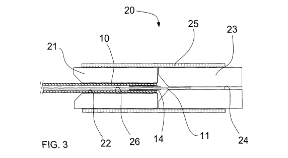
result of moisture induced sensor drift. Optical pressure element as described
in US
patent number 7689071 do not suffer from such adverse effect and they are
better suited
for FFR measurement such as for pressure guidewire described in US patent
application
number 13/389,319.
[0005]Pressure guidewires also must allow easy disconnection and reconnection
of the
guidewire to a pressure analyzer. Pressure guidewires involve the measurement
of distal
blood pressure, followed by the insertion of other interventional medical
devices such as
Percutaneous Transluminal Coronary Angioplasty (PTCA) balloon catheter over
the
- 1 -
CA 02848728 2014-02-19
WO 2013/029157 PCT/CA2012/000803
guidewire for stenting in case of significant lesion. It is however desirable
to have the
ability to reliably re-connect the guidewire to the pressure analyzer for post
stenting FFR
assessment, or for multi-vessel lesion assessment. Current electrical
connectors such as
those described in US patent nos. 4958642, 4961433, 5178159, 5240437, 5358409,
5348481, 5413508, 6196980, 6428336, 7274956 are suited for electrical
connection.
Although they have the ability to provide a reliable electrical connection in
dry conditions,
they are typically quite sensitive to conditions where the surface of the
guidewire
connector contacts are contaminated with blood residues after the removal of
the
interventional device such as PTCA balloon catheter.
(0006]A selection of prior art documents is described below. They are
discussed for
illustrative purposes only. These documents do not necessarily represent the
closest
prior art.
[0007] US patent 5125058 provides a method for optically connecting a
guidewire
mounted device to a relaying cable. The method however relies on the accuracy
of the
internal diameter of the guidewire, which is difficult to achieve. The
guidewire mounted
optical fiber interface is recessed within the guidewire, making the fiber
surface polishing
a difficult task. The optical portion that is devoted to be inserted into the
guidewire needs
to be of very small diameter, making the connector very sensitive to
mechanical damage.
[0008] US patent 5601087 relies on the addition to the guidewire shaft of a
proximal
tubing portion, often called ferrule, with accurate outside diameter for
alignment purpose.
The addition of such proximal tubing portion adds extra production steps to
the device
and represents a challenging assembly process considering the presence of
optical
parts.
[0009] US patent 6445939 also relies on the addition of a ferrule attached to
the proximal
end of the guidewire shaft. It is indeed very difficult and expensive to
machine such a
tinny precise ferrule, and to attach it to the proximal end of the guidewire
shaft.
[0010] US patent 7736301 also relies on the addition of a ferrule near the
proximal end of
the guidewire shaft. The ferrule is, in this case, not attached to the
guidewire as it is
desired to allow for rotational connection, hence further increasing the
requirement on
the diameter tolerance of the parts.
- 2 -
PCT/CA2012/000803
CA 02848728 2014-02-19
28 June 2013 28-06-2013
File no. P1831PC00
[0011] Hence, there is a need for an optical guidewire connector having the
ability to
reliably connect a guidewire mounted optical pressure sensor to an external
pressure
analyzer or a similar opto-electronic device; that is disposable, and hence
that is easy to
produce and is low in cost of material; and that is not sensitive to the
presence of
moisture or blood contamination.
SUMMARY
[0012]According to an embodiment, there is described a method for terminating
a first
optical fiber within a proximal portion of a guidewire tubing. The guidewire
tubing has an
outside diameter defined as having a tolerance of 25 pm or better. The
method
comprises centering the first optical fiber within the guidewire tubing.
[0013]According to an aspect, the method further comprises grinding,
polishing, or
etching the guidewire tubing to bring the outside diameter within a tolerance
of 25 pm
or better.
[0014]According to an aspect, a gap exists between an outside diameter of the
first
optical fiber and an inside diameter of the guidewire tubing, the method
further
comprising slipping an overlay tubing over the optical fiber to fill the gap
at least in part.
[0015]According to an aspect, the centering comprises centering the first
optical fiber
relative to the outside diameter of the guidewire tubing using an alignment
centering
tubing device, the method further comprising using an adhesive for securing
the first
optical fiber in the center of guidewire proximal portion.
[0016]According to an aspect, the alignment centering tubing device comprises
a first
ferrule having an inside diameter adapted to the outside diameter of the
guidewire tubing,
a second ferrule having an inside diameter adapted to an outside diameter of
the first
optical fiber, the method further comprising concentrically aligning the first
ferrule and the
second ferrule.
[0017]According to an aspect, the aligning the first ferrule and second
ferrule comprises
using a split sleeve over the first ferrule and second ferrule thereby holding
both ferrules
coaxially.
- 3 -
AMENDED SHEET
CA 02848728 2014-02-19
WO 2013/029157
PCT/CA2012/000803
[0018]According to an aspect, a gap exists between an outside diameter of the
first
optical fiber and an inside diameter of the guidewire tubing, and wherein the
centering
further comprising slipping an overlay tubing over the optical fiber to fill
the gap at least in
part.
[0019]According to an aspect, the alignment centering tubing device comprises
a first
ferrule having an inside diameter adapted to the outside diameter of the
guidewire tubing,
a second ferrule having an inside diameter adapted to an outside diameter of
an overlay
tubing, the method further comprising concentrically aligning the first
ferrule and the
second ferrule.
[0020]According to another embodiment, there is described a method for
connecting a
first optical fiber within a proximal portion of a guidewire tubing, the
method comprising:
centering the first optical fiber within the proximal portion of the guidewire
tubing; and
connecting the first optical fiber to a female connector comprising a second
optical fiber
having a core diameter different from a core diameter of the first optical
fiber.
[0021]According to an aspect, the method further comprises connecting the
first optical
fiber to a female connector comprising an alignment centering tubing device
comprising a
first ferrule having an inside diameter adapted to the outside diameter of the
guidewire
tubing, a second ferrule having an inside diameter adapted to an outside
diameter of a
second optical fiber for relaying an optical signal to an external signal
conditioner unit,
the method further comprising concentrically aligning the first ferrule and
the second
ferrule.
[0022]According to an aspect, the first ferrule and second ferrule are aligned
with a split
sleeve holding both ferrules coaxially.
[0023]According to another embodiment, there is described a female optical
receiving
device for connecting a first optical fiber to a second optical fiber, the
first optical fiber
being substantially centered within a proximal portion of a guidewire tubing,
the female
optical receiving device comprising a first ferrule having a longitudinal axis
and an inside
diameter adapted to an outside diameter of the guidewire tubing, a second
ferrule having
- 4 -
CA 02848728 2014-02-19
WO 2013/029157 PCT/CA2012/000803
a longitudinal axis and an inside diameter adapted to an outside diameter of
the second
optical fiber, the longitudinal axis of the first ferrule being aligned with
the longitudinal
axis of the second ferrule.
[0024]According to an aspect, the device further comprises a split sleeve
slipped and
fixed over the first ferrule and the second ferrule simultaneously thereby
aligning the
longitudinal axis of the first ferrule and the longitudinal axis of the second
ferrule.
[0025]According to an aspect, the second optical fiber has a core diameter
different from
a core diameter of the first optical fiber, the second optical fiber being
fixed within the
second ferrule.
[0026]According to another embodiment, there is described, an interface
connector
handle for connecting a first optical fiber to a second optical fiber, the
first optical fiber
being substantially centered within a proximal portion of a guidewire tubing,
the second
optical fiber being routed through and extending from an optical interface
cable, the
interface connector handle comprising a biasing assembly for urging the first
optical fiber
into contact with the second optical fiber.
[0027]According to an aspect, the handle further comprises a female optical
receiving
device at a distal end of the second optical fiber and wherein first optical
fiber is for
insertion in the female optical receiving device in order to contact the
second optical
fiber.
[0028]According to an aspect, the biasing assembly comprises a collet through
which
the guidewire tubing is pushed and held in place when the collet is in a
closed position.
[0029]According to an aspect, the biasing assembly further comprises a biasing
device
and a connector cap through which the guidewire tubing is slid toward the
female optical
receiving device, the connector cap capable of movement in a direction, the
biasing
device exercising a counter force opposite the direction of movement of the
connector
cap, the counter force forcing the collet toward the closed position.
- 5 -
CA 02848728 2014-02-19
WO 2013/029157 PCT/CA2012/000803
[0030]According to another embodiment, there is described a method for
terminating a
first optical fiber within a proximal portion of a guidewire tubing, the
method comprising
centering the first optical fiber relative to the outside diameter of the
guidewire tubing
using an alignment centering tubing device, the method further comprising
using an
adhesive for securing the first optical fiber in the center of guidewire
proximal portion.
[0031]According to an aspect, the alignment centering tubing device comprises
a first
ferrule having an inside diameter adapted to the outside diameter of the
guidewire tubing,
a second ferrule having an inside diameter adapted to an outside diameter of
the first
optical fiber, the method further comprising concentrically aligning the first
ferrule and the
second ferrule.
[0032] According to an aspect, the aligning the first ferrule and second
ferrule comprises
using a split sleeve over the first ferrule and second ferrule thereby holding
both ferrules
coaxially.
BRIEF DESCRIPTION OF THE DRAWINGS
[0033]The accompanying drawings, which are included to provide a further
understanding of the invention are incorporated and constitute a part of this
specification,
illustrate an exemplary embodiment of the invention that together with the
description
serve to explain the principles of the invention.
[0034] FIG. 1 is a schematic diagram of the guidewire assembly connection
showing a
cross-section of an interface cable handle according to an embodiment;
[0035] FIG. 2 is a schematic diagram showing a cross-section of the proximal
end of the
guidewire with its optical fiber protruding therefrom according to an
embodiment;
[0036] FIG. 3 is schematic diagram showing a cross-section of an alignment
assembly
device for aligning the optical fiber in the center of the proximal end of
guidewire
according to an embodiment;
[0037]FIG. 4 is schematic diagram showing a cross-section of guidewire
proximal end
terminated to provide connectivity according to an embodiment;
- 6 -
CA 02848728 2014-02-19
WO 2013/029157 PCT/CA2012/000803
[0038] FIG. 5 is a schematic diagram showing a cross-section of guidewire
proximal end
terminated to provide connectivity according to another embodiment that
comprises an
overlay tubing;
[0039] FIG. 6 is a schematic diagram showing a cross-section of an alignment
assembly
device for aligning the optical fiber with overlay tubing in the center of the
proximal end of
guidewire according to another embodiment;
(0040] FIGS. 7a and 7b are schematic diagrams showing cross-sections of an
optical
female connectivity part used to receive a guidewire proximal end and aligning
respective
fibers together according to an embodiment;
[0041] FIG. 8 is a schematic diagram showing a cross-section view of a handle
which can
be used in a method for holding female receiving optical parts at the end of
an optical
interface cable according to an embodiment;
[0042]FIG. 9 is a schematic diagram showing a side view of the handle of FIG.
8; and
[0043] FIGS. 10a and 10b are schematic diagrams showing a cross-section view
of the
handle of FIG. 8 in the open position (FIG. 10a) and the closed position (FIG.
10b).
DETAILED DESCRIPTION
[0044]In the following description of the embodiments, references to
accompanying
drawings are by way of illustration of an example by which the invention may
be
practised. It will be understood that other embodiments may be made without
departing
from the scope of the invention disclosed.
[0045]The system 2 for measuring FFR is shown in Fig. 1. It comprises a
guidewire 1
instrumented with an optical pressure sensor 7 near the distal end (toward the
patient).
The guidewire 1 is therefore built with a hollow tubing (i.e., a guidewire
tubing) for
accommodating the optical fiber (not shown). The guidewire proximal end
(toward the
clinician) is terminated with a connectivity end for connecting to optical
interface cable 5.
The optical interface cable 5 is used to relay the optical signal from signal
conditioner unit
3 (e.g., an optical analyzer) to guidewire mounted optical pressure sensor 7,
and back to
signal conditioner unit 3. Guidewire 1 comprises an internal optical fiber
(not shown) that
carries the light signal to the optical pressure sensor 7 and back to signal
conditioner unit
- 7 -
CA 02848728 2014-02-19
WO 2013/029157 PCT/CA2012/000803
3. In this respect, both optical fiber in the guidewire 1 and the optical
fiber in the optical
interface cable 5 need to be coaxially aligned and held in contact during use.
The distal
end of the optical interface cable 5 is terminated with optical alignment
device 6 (also
referred to herein as the female optical receiving device) that is embedded
within the
interface cable handle 4.
[0046]Fig. 2 shows a first embodiment of the proximal portion 10 of the
guidewire 1 such
that after some further processing as detailed with reference to Fig. 3 herein
below, it can
be connectorized to an optical interface cable 5 (see Fig. 7a). Guidewire
proximal portion
outer diameter 13 of the guidewire 1 has an accurate and precise diameter.
[0047]The first optical fiber 11 can be aligned in the center of the guidewire
tubing 12
with a positioning apparatus having the ability to mechanically position the
first optical
fiber 11 in the center of the guidewire 1, i.e., concentric with the end of
the guidewire
proximal portion 10. The position of the first optical fiber 11 relative to
the guidewire
tubing 12 is measured by methods such as those available from Beta LaserMike,
Dayton,
Ohio.
[0048]The optical fiber alignment method shown in Fig. 3 is a preferred method
because
its compactness does not require a high level of mechanical stability for the
assembly
apparatus, while also being a self-alignment method. The alignment assembly
device 20
(also known as an alignment centering tubing device) is made of a first
alignment ferrule
21, tubing or similar device having a precise internal diameter 22 adapted to
receive the
guidewire proximal portion 10. By way of example, the first alignment ferrule
21 is
preferably made with a commercial optical fiber alignment ferrule, either made
of
ceramic, zirconium, glass, stainless steel or other material providing
adequate support
and alignment accuracy. In the following, it is understood that ferrule is
either a ferrule, a
tubing or other similar device made of ceramic, zirconium, glass, stainless
steel or other
adequate material. Commercial ferrules for optical fibers are made with
tolerances on
eccentricity and hole diameter of the order of 1 micron. A preferred outside
diameter of
such ferrules is typically of 1.25 mm, although it can be of other diameters
such as 2.5
mm. The second alignment ferrule 23 is used to receive the first optical fiber
11 and it is
therefore selected to have an internal diameter 24 that matches the diameter
of the
- 8 -
. . ,
PCT/CA2012/000803
CA 02848728 2014-02-19
28 June 2013 28-06-2013
File no. P1831PC00
optical fiber cladding. Both ferrules are then coaxially aligned with the use
of a split
sleeve 25.
[0049] Proper centering of the first optical fiber 11 within the guidewire
proximal portion
is therefore possible considering the guidewire proximal portion outer
diameter 13 is
accurate. The guidewire proximal portion 10 shall have an guidewire proximal
portion
outer diameter 13 with a tolerance better than 25 pm or 0.001, and
preferably it shall
have a tolerance better than 12.6 pm or 0.0005". One preferred method of
obtaining a
diameter with an accuracy of 12.6 pm or 0.0005" or better is to grind the
guidewire
proximal portion 10 of the guidewire tubing 12 outer surface using a center-
less grinder
or other types of grinders known by those skilled in the art to be appropriate
for this task.
It is also obvious for those skilled in the art that other methods such as
electro-etching
can be used for the same purpose. The first optical fiber 11 is then aligned
in the axial
center of the guidewire tubing 12, and fixed in place using an adhesive 14.
[0050]Alignment assembly device 20 shown in Fig. 3 is therefore used to center
the first
optical fiber 11 in the guidewire tubing 12. The optical guidewire is prepared
by letting the
first optical fiber 11 protrude out of the guidewire tubing 12. The required
amount of
adhesive 14 is then provided to fill the gap between the first optical fiber
11 and the
internal surface 26 of the guidewire proximal portion 10, and left uncured.
The guidewire
proximal portion 10 with protruding first optical fiber 11 is then inserted
into the first
alignment ferrule 21 and pushed such that the first optical fiber 11 enters
into the second
alignment ferrule 23. Depending on specific alignment assembly device 20, the
guidewire
proximal portion 10 can be pushed close to or in intimate contact with the
second
alignment ferrule 23, hence minimizing optical fiber misalignment that may be
caused by
the first optical fiber 11 bending outside second alignment ferrule 23. The
adhesive 14 is
then cured according to known adhesive curing methods.
[0051]An alternative method consists in inserting the guidewire proximal
portion 10
within the first alignment ferrule 21 and pushed such that the first optical
fiber 11 enters
into the second alignment ferrule 23 with no adhesive yet. The required amount
of
adhesive 14 for filling the gap between the first optical fiber 11 and the
internal surface
26 of the guidewire proximal portion 10 is then provided, followed by a curing
step of the
- 9
AMENDED SHEET
CA 02848728 2014-02-19
WO 2013/029157
PCT/CA2012/000803
adhesive 14. This alternative method helps in preventing the adhesive 14 from
also filling
the gap between the guidewire proximal portion 10 and the internal surface of
the first
alignment ferrule 21, allowing an easy removal of the guidewire assembly after
the
adhesive 14 is cured.
[0052]Once the adhesive 14 is cured, the guidewire with centered first optical
fiber 11 is
retrieved from the alignment assembly device 20 to be terminated as shown in
Fig. 4.
The guidewire optical termination surface 31 of the guidewire is polished such
that the
first optical fiber 11 can be connected to the interface cable optical fiber
(not shown
here). Although the guidewire optical termination surface 31 can be polished
on a hard
surface, it is preferred to polish the guidewire proximal portion 10 on a soft
polishing
surface such that the optical fiber termination is provided with the ability
to form a
physical contact with the interface cable optical fiber.
[0053]The optical connectorization method shown in Fig. 4 is however not
optimal. The
relatively large amount of adhesive 14 used to fill the gap 32 between the
first optical
fiber 11 and the internal diameter of the guidewire tubing 12 makes such
optical
connection susceptible to optical fiber misalignment during assembly and over
time. As
the amount of adhesive 14 increases during assembly, the risk of having the
adhesive 14
unevenly distributed increases, which in turn increases the risks of unevenly
pulling the
first optical fiber 11 off the axial center. In use, all adhesives have the
tendency to swell
over time, especially when in presence of moisture and with temperature
change. A
relatively large amount of adhesive 14 therefore makes the optical termination
more
unstable.
[0054]The termination shown in Fig. 5 is a variation of the one shown in Fig.
4, where
the gap between the first optical fiber 11 and the internal surface 26 of the
guidewire
proximal portion 10 is partially filled with an overlay tubing 36. In an
embodiment, the
overlay tubing 36 is selected to precisely match the first optical fiber 11.
The amount of
adhesive 14 holding the fiber in the center of the guidewire proximal portion
10 is
significantly reduced, hence long term stability of the optical connection is
assured.
- 10 -
CA 02848728 2014-02-19
WO 2013/029157 PCT/CA2012/000803
[0055]The optical connection illustrated in Fig. 5 can be terminated using the
same
optical assembly device shown in Fig. 3. The overlay tubing 36 in this case
would just
barely extend further than the guidewire proximal portion 10 during assembly.
[0056] For those cases where the overlay tubing 36 is very precise, it may
however be
desirable to use the alignment assembly device 27 shown in Fig. 6a, where the
second
alignment ferrule 41 has an internal diameter adapted to receive the overlay
tubing 36.
However, misalignment errors caused by tolerances of inner diameter 37 and
outer
diameter 38 of the overlay tubing 36 add up to the final coaxial positioning
error of the
first optical fiber 11, potentially leading to sub-optimal concentricity. It
has been found
that the optical fiber provides adequate stiffness for aligning concentrically
with the
guidewire when aligned with set-up and alignment method shown in Fig. 3. A
preferred
method consists in using an overlay tubing that does not precisely fit over
the first optical
fiber 11.
[0057]Fig. 6b illustrates such a preferred assembly method and alignment
assembly
device 20 using an overlay tube 39 that does not precisely fit over the first
optical fiber
11. The concentric alignment of the first optical fiber 11 within the
guidewire proximal
portion 10 is assured by inserting the first optical fiber 11 in a second
alignment ferrule
23 having an internal diameter matching the outside diameter of the first
optical fiber 11,
while the overlay tube 39 purpose is mainly for filling the gap 32 (shown in
Fig. 4).
[0058]The above embodiments describe various methods and devices for making an
optical connection at the proximal end of an optical guidewire. There is
however also a
need for a female part receiving the guidewire optical connection to provide
an optical
connection with the optical interface cable 5 for relaying the optical signal
to a signal
conditioner unit 3 (see Fig. 1).
[0059]Fig. 7a and 7b show the optical parts used to construct such a female
optical
receiving device 6. The female optical receiving device 6 is built in a way
very similar to
the alignment assembly device 20 shown in Fig. 3. The first ferrule 51 herein
is also used
to receive the guidewire 1, with the inner diameter 52 adapted to receive the
guidewire
proximal portion 10. First ferrule 51 and second ferrule 53 are aligned and
held together
using split sleeve 54. The second ferrule 53 is however selected to receive
the second
- 11 -
CA 02848728 2014-02-19
WO 2013/029157
PCT/CA2012/000803
optical fiber 55 routed through the optical interface cable 5 (see Figs. 1 and
8). By way of
an example, the optical interface cable 5 comprises the second optical fiber
55 having a
core diameter of 62.5 pm and a cladding diameter of 125 pm. In this case, the
second
ferrule 53 is selected with a diameter of 126 pm or 127 m. The second optical
fiber 55 is
bonded inside the second ferrule 53 and polished so as to provide an adequate
optical
surface 56 compatible with the guidewire optical termination.
[0060] Fig. 7b shows the female optical receiving device 6 with the guidewire
proximal
portion 10 engaged within the first ferrule 51. The optical connection will
take place with
minimal losses provided that the first optical fiber 11 is coaxially aligned
with the second
optical fiber 55, and provided that the faces of both first optical fiber 11
and second
optical fiber 55 are in intimate contact.
[0061] Fig. 8 shows an interface connector handle 4 which can be used in a
method for
holding the female optical receiving device 6. A second optical fiber 55 is
connected to
the female optical receiving device 6 on one side, and runs through the
optical interface
cable 5 on the other side. The female optical receiving device 6 is held in
the center of
the interface connector handle 4 and pushed against a surface 68 with the help
of a
spring 67. The guidewire proximal portion 10 (see Fig. 7b) is inserted through
the conical
entrance 66 of the connector cap 61, it is pushed through the collet 63 then
inside the
female optical receiving device 6 such that the guidewire optical termination
surface 31
(see Fig. 4) and the optical surface 56 (see Fig. 7a) of the second optical
fiber 55 are in
contact. The user can then tighten the connector cap 61. Connector cap
proximal end 62
therefore pushes on collet 63 which results in closing such collet 63 by
counter force
exerted by spring 65 through seat 70. It is understood that spring 65 can be
replaced by
similar device such as rubber tube or other biasing device. The action of
pushing the
tightening collet 63 into seat 70 has the effect of closing the tightening
collet 63 onto the
guidewire proximal portion 10, firmly holding it in place.
[0062]According to an embodiment, the interface connector handle 4 comprises a
biasing assembly (not number) for urging the first optical fiber 11 into
contact with the
second optical fiber 55. The biasing assembly may comprise collet 63 through
which the
guidewire 1 is pushed and held in place when the collet 63 is in a closed
position. The
- 12 -
CA 02848728 2014-02-19
WO 2013/029157 PCT/CA2012/000803
biasing assembly may further comprise a biasing device (spring 65) and
connector cap
through which the guidewire tubing is slid toward the female optical receiving
device, the
connector cap 61 capable of movement in a direction. The biasing device
exercises a
counter force opposite the direction of movement of the connector cap 61 and
the
counter force forces the collet 63 toward the closed position.
[0063]One aspect of the method using interface connector handle 4 is to assure
and
maintain a good physical contact between both the optical interface of
guidewire 1 and
the optical interface of female optical receiving device 6. Physical contact
is assured by
the displacement of the guidewire proximal portion 10 provided upon tightening
the
connector cap 61. Upon tightening connector cap 61, collet 63 first closes and
grips the
guidewire proximal portion 10, forcing guidewire optical termination surface
31 (see Fig.
4) to push against the optical surface 56 of the second optical fiber 55 (see
Fig. 7a). This
action is illustrated in Figures 10a and 10b.
[0064] Fig. 10a shows the connector handle in an open position and Fig. 10b
shows the
connector handle in a closed (downward) position, where one can see the
downward
position in Fig. 10b of both the collet 63 and the female optical receiving
device 6. The
downward displacement of guidewire 1 pushing against female optical receiving
device 6
is provided by the pitch of the sliding rail 72 and its interaction with
protrusion 71 (see
Fig. 9). The downward displacement of the guidewire 1 against the female
optical
receiving device 6 translates into contacting pressure between both optical
termination
interfaces (guidewire optical termination surface 31 (see Fig. 4) and the
optical surface
56 of the second optical fiber 55 (see Fig. 7a). The force is provided by the
spring 67 that
is pushing against female optical receiving device 6. The spring 67, applies
its pressure
on the female optical receiving device 6 through a flange 69 that is mounted
on the
second ferrule 53 (see Fig. 7a). The pressure between the optical interfaces
assures a
good physical contact and therefore a good optical connection.
[0065]The above method of exerting a mutual pressure on the optical
termination
surfaces of both a guidewire and an optical receiving device is described by
way of an
example. Other methods of imposing a relative movement between the guidewire
and
the optical receiving device are understood to be within the scope of the
present
- 13-
CA 02848728 2014-02-19
WO 2013/029157
PCT/CA2012/000803
description. For example, there may exist a method for moving the internal
receiving
device apart from the guidewire prior to guidewire insertion, followed by a
release after
the guidewire is tightened within a connector handle.
[0066]The quality of the optical connection is related to the relative
centering of both
optical fiber axis where they interface. One method for reducing the tolerance
on this
centering is to use a second optical fiber 55 in the optical interface cable 5
with a core
diameter different from the core diameter of the optical fiber (not shown) of
the guidewire
1. Although this approach is not always possible, there are optical measuring
methods
that are well suited for such a strategy. For instance, the pressure sensor
described in
US 7689071 and associated signal conditioning unit described in US 7259862 are
well
suited for the implementation of such a strategy.
[0067]While preferred embodiments have been described above and illustrated in
the
accompanying drawings, it will be evident to those skilled in the art that
modifications
may be made without departing from this disclosure. Such modifications are
considered
as possible variants comprised in the scope of the disclosure.
- 14 -