Note: Descriptions are shown in the official language in which they were submitted.
HANGING PRODUCT DIVIDER AND PUSHER SYSTEMS AND METHODS FOR
DIVIDING, PUSHING AND/OR DISPENSING ONE OR MORE RETAIL PRODUCTS
[0001]
FIELD OF THE DISCLOSURE
[0002] The present disclosure relates to hanging merchandising product divider
and pusher systems,
quick-load merchandising pusher systems, and methods for dividing, pushing and
dispensing one or more
retail products. The present merchandising systems and methods may be utilized
in a retail environment
to secure, store, display and/or dispense the one or more retail products.
SUMMARY OF THE DISCLOSURE
[0003] In embodiments, a hanging merchandising product divider and pusher
system may dispense retail
products. The hanging system may have a first divider having a length defined
between a front end and a
rear end and a height defined between a top end and a bottom end, at least one
second divider having a
length defined between a front end and a rear end and a height defined between
a top end and a bottom
end, and at least one connection plate connecting at least a portion of bottom
end of the first divider to at
least a portion of the bottom end of the second divider. Further, the hanging
system may have at least one
rear support connector connecting at least a portion of the rear end of the
first divider to at least a portion
of the rear end of the second divider, a first pocket defined by the first and
second dividers, the
connection plate, the rear support connector and the front ends of the first
and second dividers, wherein
the first pocket is sized or configured to receive one or more first retail
products. Moreover, the hanging
system may have a pusher paddle movably connected to the connection plate
between the first and second
dividers, wherein the pusher paddle is urged towards a front-side of the
hanging system such that the
pusher paddle moves the one or more products towards the front-side of the
hanging system when the one
or more first retail products are positioned within the first pocket of the
hanging system, and rear
mounting hangers located at a back-side of the hanging system, wherein the
rear mounting hangers are
sized or configured such that the hanging system is mountable to an upright
mount cross bar, an upright, a
rear mount track or a hanging mount bracket via the rear mounting hangers.
CA 2848791 2019-04-12
CA 02848791 2014-04-11
-2-
[0004] In an embodiment, the system may have a least one flip ticket component
connecting the front
ends of the first and second dividers, wherein flip ticket component maintains
the dividers in a
substantially horizontal alignment.
[0005] In an embodiment, the system may have a graphic mount positioned
adjacent to the front end and
the bottom end of one of the first and second dividers, wherein the flip
ticket component is mountable to
the graphic mount.
[0006] In an embodiment, the system may have a fence insert located between
the front ends of the first
and second dividers, wherein the fence insert extends upward from the bottom
sides of the first and
second dividers and is configured to retain the one or more first retail
products within the first pocket of
the hanging system.
[0007] In an embodiment, the system may have at least one second pocket sized
or configured to receive
one or more second retail products, wherein the first and second retail
products have different shapes,
sizes or configurations.
[0008] In an embodiment, the system may have a third divider connected to the
first divider, wherein the
second pocket is located between the first divider and the third divider.
[0009] In an embodiment, the system may have at least one third pocket sized
or configured to receive
one or more third retail products, wherein the first, second and third retail
products have different shapes,
sizes or configurations.
[0010] In an embodiment, the system may have a fourth divider connected to the
third divider, wherein
the third pocket is located between the third divider and the fourth divider.
[0011] In an embodiment, the system may have a product retaining fence formed
along the front side of
at least one of the first and second dividers, wherein the product retaining
fence is sized or configured to
prevent the one or more first retail products from being pushed outwardly from
the front-side of the
hanging system by the pusher paddle when the one or more first retail products
are positioned within the
first pocket of the hanging system.
[0012] In an embodiment, the product retaining fence may be is positioned at
an angle with respect to the
lengths of the first and second dividers.
CA 02848791 2014-04-11
-3-
[0013] In an embodiment, the system may have a product alignment rib provided
within the first pocket
sized or configured to align a first product of the one or more first retail
products, located adjacent to the
front-side of the hanging system, such that the first product is substantially
parallel to the product
retaining fence when the one or more first retail products are positioned
within the first pocket of the
hanging system.
[0014] In embodiments, a method may dispense retail products and may secure
the hanging system to a
shelf, a pegboard, a slatwall or uprights by mounting the hanging system to
the shelf, the pegboard, the
slatwall or the upright via the rear mounting hangers located at the rear-side
of the hanging system.
[0015] In an embodiment, the method may mount the hanging system to the
pegboard or slatwall via a
hanging mount bracket, at least one peg clip and the rear mounting hangers.
[0016] In an embodiment, the method may mount the hanging system to the
uprights via an upright
mount cross bar and the rear mounting hangers.
[0017] In an embodiment, the method may mount the hanging system to the
uprights via an adjustable
depth crossbar and the rear mounting hangers, wherein the hanging system is
movable inwardly or
outwardly with respect to the uprights via the adjustable depth crossbar.
[0018] In an embodiment, the method may mount the hanging system to the shelf
via a front shelf mount
track, a rear mount track, a toe clip of the hanging system and a bottom rear
mounting hanger of the rear
mounting hangers.
[0019] In an embodiment, the method may position a first retail product in the
first pocket of the hanging
system.
[0020] In embodiments, a system may dispense retail products and may have a
hanging system
comprising a first divider having a length defined between a front end and a
rear end and a height defined
between a top end and a bottom end, at least one second divider having a
length defined between a front
end and a rear end and a height defined between a top end and a bottom end, at
least one rear support
connector connecting at least a portion of the rear end of the first divider
to at least a portion of the rear
end of the second divider, wherein the at least one rear support connector
comprises a lower rear
mounting hanger and an upper rear mounting hanger, wherein the lower and upper
rear mounting hangers
extend outwardly with respect to a back-side of the hanging system and
downwardly with respect to the
top ends of the dividers. The hanging system may also have a first pocket
located between the first and
second dividers, wherein the first pocket is sized or configured to receive
one or more first retail products,
CA 02848791 2014-04-11
-4-
and a movable pusher paddle located between the first and second dividers,
wherein the pusher paddle is
configured to move the one or more retail products towards a front-side of the
hanging system when the
one or more retail products are positioned in the first pocket of the hanging
system.
100211 In an embodiment, the system may have (i) a hanging mount bracket
attached to the hanging
system via the lower and upper rear mounting hangers and at least one peg clip
connected to the hanging
mount bracket, (ii) an upright mount crossbar attached to the hanging system
via the lower and upper rear
mounting hangers, (iii) a moveable adjustable depth crossbar attached to the
hanging system via the lower
and upper rear mounting hangers or (iv) front and rear shelf mount tracks
attached to the hanging system
via a toe clip and the lower rear mounting hanger.
100221 In an embodiment, the system may have a third divider connected to the
second divider such that
a second pocket is formed between the second and third dividers, wherein the
second pocket is sized or
configured to receive at least one second retail product, wherein the one or
more first retail products and
the at least one second retail product have different shapes, sizes or
configurations.
BACKGROUND OF THE DISCLOSURE
100231 Pegboard hooks are a common display and/or organizational merchandising
tool utilized in retail
environments. The pegboard hooks are utilized to organize one or more retail
products that are light
weight, oddly shaped and/or small in size. These retail products are otherwise
difficult to neatly
merchandise on traditional shelves. The hooks suspend the retail products from
cut-outs in the packaging
of the retail products, and limit their (i.e., the hooks) uses to specially
designed packages. There are many
other disadvantages and limitations to merchandising with the pegboard hooks.
For example, one
disadvantage with respect to pegboard hooks is their adjustability. Typically,
pegboard hole spacing is
about one inch between centres and a typical hook requires two holes for
mounting. As a result, the
minimum distance between hook centres is about two inches. However, some slim
retail products, such
as, for example, tooth brushes have an average width of, for example, about
one inch. Therefore, in some
cases, there is a gap or distance of unusable space between adjacent retail
products which, thus, limits the
number of product facings which may be provide when utilizing pegboard hooks.
[0024] Peg hooks often make it difficult for a customer of the retail products
to select a specific retail
product hanging near the back of the hook, without disturbing, dislodging or
removing other retail
products which are positioned in-front of the specific retail product desired
by the customer. This often
results in one or more of the other retails products being removed from and/or
unattached from the peg
hooks by movements of the customer. As a result, one or more of the other
retail products may fall from
CA 02848791 2014-04-11
-5-
the peg hooks and/or be damaged by such fall. Often, a mounting point on the
packaging of the fallen
retail product(s) becomes damaged from such fall or in the process of, which
makes it very difficult or
completely impossible to re-merchandise the fallen and damaged retail
product(s) on the peg hook(s).
[0025] Without continuous aisle facing and upkeep by the merchandiser or
employees of the
merchandiser, aisle sections merchandised with the peg hooks quickly become
very disorganized and/or
visually unappealing to the customer.
[0026] In the retail industry, it has long been know that appearance is key
and very important in selling
retail products. If a retail product is displayed in a clean and organize
manner, it is easier for the customer
to find and select the items the customer wishes to purchase. A retail store
often spends a large amount of
time and effort organizing, aligning and facing the retail products in order
to maintain a clean visual
presence and/or appearance. One merchandising solution that retailers have
employed to cleanly display
the retail products are pusher systems. The pusher system are spring loaded
merchandising components,
often affixed to store shelves, used to push products forward as customers
removes the products at the
front of the pusher system. One drawback to these pusher systems is that they
require added vertical
space between shelves in order to incorporate the on-shelf components as well
as space needed to lift a
product up and over a retaining fence. This need for extra vertical space can
sometimes limit the number
of shelves capable to fit into a specific store section which, in turn,
reduces retail product holding power
of the retailers. For store employees, loading the pusher tracks can often
been time consuming and
cumbersome as one hand is required to hold back the product already in the
pusher system while the other
hand is required to load new retail products into the pusher system.
[0027] The merchandising systems and methods set forth in the present
disclosure divide, push, secure,
store, display and dispense retail products in such a manner that effectively
prevents the retail products
from falling and being damaged while also maintaining organization of the
retail products and keeping
the aisle sections visually appealing to customers. Moreover, the systems and
methods set forth in the
present disclosure provide a quick-load pusher system which maintains the
retail products in clean and
organized manner and/or appearance and allows quick and easier loading of the
retail products into the
pusher system.
SUMMARY OF THE DISCLOSURE
[0028] In embodiments, a quick-load merchandising product pusher system for
dispensing retail products
is provided. The pusher system may have a fixed portion having a front end, a
rear end located opposite
with respect to the front end of the fixed portion, a top side and a bottom
side located opposite with
CA 02848791 2014-04-11
-6-
respect to the top side of the fixed portion, wherein ramps are provided on
the top side of the fixed
portion, extend outwardly with respect to the top side of the fixed portion,
and are located adjacent to the
front end of the fixed portion and a movable track movably connected to the
top side of the fixed portion,
wherein the movable track has a front end, a rear end located opposite with
respect to the front end of the
movable track, a top side and a bottom side located opposite with respect to
the top side of the movable
track, wherein one or more track stoppers are provided on the bottom side of
the movable track, extend
outward with respect to the bottom side of the movable track and are located
adjacent to the rear end of
the pusher system. The pusher system may have a pusher paddle connected to the
top side of the movable
track, wherein the pusher paddle, the front end of the movable track and the
top side of the movable track
define a first area that is sized or configured to receive one or more retail
products, wherein the pusher
paddle is configured to move one or more retail product forward away from the
rear side of the movable
track and front retainer teeth connecting the fixed portion and the movable
track, wherein the front
retainer teeth are provided on the top side and at the front end of the fixed
portion and extend outwardly
with respect to the top side of the fixed portion. The movable track may be
movable to a closed position
or to an extended position, wherein, when the movable track is located in the
closed position, the rear end
and the one or more track stoppers of the movable track are located adjacent
to the rear end of the fixed
portion and, when the movable track is located in the extended portion, the
rear end and the one or more
track stoppers of the movable track are located adjacent to the ramps of the
fixed portion and the front
retainer teeth abuts a portion of the pusher paddle and restricts forward
movement of the pusher paddle as
the movable track is moved to the extended position.
[0029] In an embodiment, when the movable track is located in the extended
position, the one or more
track stoppers of the movable track may abut the ramps of the fixed portion
and forward movement of the
movable track is restricted via the one or more track stoppers of the movable
track and the ramps of the
fixed portion.
[0030] In an embodiment, when the movable track is located in the extended
position, the pusher paddle,
the front side of the movable track and the top side of the movable track may
define a second area that is
sized or configured to receive one or more retail products, wherein the second
area is larger than the first
area.
[0031] In an embodiment, the pusher system may have a first mount provided at
the rear end of the fixed
portion and configured to mount the fixed portion to retail merchandising
aisle uprights.
CA 02848791 2014-04-11
-7-
[0032] In an embodiment, the first mount may have one or more hooks, one or
more pegs, a horizontal
flange or a vertical flange.
[0033] In an embodiment, the pusher system may have a front plate connected to
the front end of the
movable track, wherein, when one or more retail products are positioned within
the pusher system, the
one or more retail products are located between the front plate and the pusher
paddle.
[0034] In an embodiment, the pusher system may have loading lock tabs
connected to the ramps of the
fixed portion, wherein the loading lock tabs extend outwardly away from the
top side of the fixed portion,
and loading lock ramps provided on the bottom side of the movable track and
located between the one or
more track stoppers and the front side of the movable track, wherein the
loading locks tabs abut the
loading lock ramps when the movable track is positioned in the extended
position.
[0035] In an embodiment, the pusher system may have dividers connected to both
right and left sides of
the movable track, wherein the dividers extend outwardly away from the right
and left sides of the
movable track and away from the top side of the movable track.
[0036] In an embodiment, the dividers may be wire dividers or molded dividers.
[0037] In an embodiment, one or more holes may be formed through the molded
dividers along a length
of the molded dividers.
[0038] In an embodiment, the pusher system may have a modular baffle connected
to a bottom side of
the fixed portion, wherein the modular extends outwardly away from right and
left sides of the fixed
portion.
[0039] In an embodiment, the pusher system may have a retail product position
in the first area defined
between the pusher paddle and the front and top sides of the movable track.
[0040] In embodiments, a method for producing a quick-load retail
merchandising product pusher
system may dispense retail products. The method may movable connect a movable
track to a fixed
portion via front retaining teeth of the fixed portion, wherein the fixed
portion has a front end, a rear end
located opposite with respect to the front end of the fixed portion, a top
side and a bottom side located
opposite with respect to the top side of the fixed portion, wherein the
movable track has a front end, a rear
end located opposite with respect to the front end of the movable track, a top
side and a bottom side
located opposite with respect to the top side of the movable track, wherein
the front retainer teeth are
provided on the top side and at the front end of the fixed portion and extend
outwardly with respect to the
CA 02848791 2014-04-11
-8-
top side of the fixed portion. Further, the method may connect a pusher paddle
to the top side of the
movable track, wherein the pusher paddle, the front end of the movable track
and the top side of the
movable track define a first area that is sized or configured to receive one
or more retail products, wherein
the pusher paddle is configured to move one or more retail product forward
away from the rear side of the
movable track. The movable track may be movable to a closed position or to an
extended position,
wherein, when the movable track is located in the closed position, the rear
end of the movable track is
located adjacent to the rear end of the fixed portion and, when the movable
track is located in the
extended portion, the rear end of the movable track is located adjacent to the
front side of the fixed
portion and forward movement of the pusher paddle is restricted by the front
retainer teeth of the fixed
portion as the movable track moves to the extended position.
[0041] In an embodiment, the method may form ramps on the top side of the
fixed portion that extend
outwardly with respect to the top side of the fixed portion and are located
adjacent to the front end of the
fixed portion, and form one or more track stoppers on the bottom side of the
movable track that extend
outward with respect to the bottom side of the movable track and are located
adjacent to the rear end of
the pusher system, wherein, when the movable track is located in the extended
position, the one or more
track stoppers of the movable track abut the ramps of the fixed portion and
forward movement of the
movable track is restricted via the one or more track stoppers of the movable
track and the ramps of the
fixed portion.
[0042] In an embodiment, the method may connect at least one divider to a
right or left side of the fixed
portion, wherein the at least one divider extends outwardly away from the
fixed portion and away from
the top side of the fixed portion.
100431 In an embodiment, the method may move the movable track to the closed
position or the opened
position.
[0044] In embodiments, a retail merchandising gondola section may dispense
retail products. The
gondola section may have retail merchandising aisle uprights and the pusher
system mounted to the aisle
uprights via the first mount of the pusher system.
[0045] In an embodiment, the gondola section may have a second mount connected
to the retail
merchandising aisle uprights for connecting the first mount of the pusher
system to the retail
merchandising aisle uprights, wherein the second mount comprises a retail
merchandizing shelf, a retail
merchandizing crossbar or a retail merchandising peg board.
CA 02848791 2014-04-11
-9-
[0046] In an embodiment, the gondola section may have a fastener for
connecting the first mount of the
pusher system to the second mount of the gondola section, wherein the fastener
is a horizontal lip shelf
extrusion or a vertical lip shelf extrusion.
[0047] In an embodiment, the gondola section may have at least one retail
product position within pusher
system.
BRIEF DESCRIPTION OF THE DRAWINGS
[0048] So that the features and advantages of the present disclosure can be
understood in detail, a more
particular description of the merchandising systems and methods may be had by
reference to the
embodiments thereof that are illustrated in the appended drawings. It is to be
noted, however, that the
appended drawings illustrate only some embodiments of the present systems and
methods and are
therefore not to be considered limiting of its scope, for the merchandising
systems and methods may
admit to other equally effective embodiments.
[0049] FIG. 1 illustrates a perspective view of a divider and pusher system
for more than one retail
product in an embodiment.
[0050] FIG. 2 illustrates an exploded perspective view of a divider and pusher
system in an embodiment.
[0051] FIG. 3A illustrates a first side perspective view of a first divider
component in an embodiment;
and FIG. 3B illustrates a second side perspective view of the first divider
component shown in FIG. 3A in
an embodiment.
[0052] FIG. 4A illustrates a first side perspective view of a second divider
component in an embodiment;
and FIG. 4B illustrates a second side perspective view of the second divider
component as shown in FIG.
4A in an embodiment.
[0053] FIG. 5A illustrates a first side perspective view of a third divider
component in an embodiment;
and FIG. 5B illustrates a second side perspective view of the third divider
component as shown in FIG.
5A in an embodiment.
[0054] FIG. 6 illustrates a cross-sectional view of a divider and pusher
system in an embodiment.
[0055] FIG. 7A illustrates a perspective view of a first connection plate in
an embodiment; FIG. 7B
illustrates a perspective view of a second connection plate in an embodiment;
and FIG. 7C illustrates a
perspective view of a pusher paddle in an embodiment.
CA 02848791 2014-04-11
-10-
[0056] FIG. 8A illustrates a perspective view of a hanging mount bracket in an
embodiment; FIG. 8B
illustrates a perspective view of an upright mount cross bar in an embodiment;
and FIG. 8C illustrates a
perspective view of a clip in an embodiment.
[00571 FIG. 9A illustrates a perspective view of front shelf mount track in an
embodiment; and FIG. 9B
illustrates a perspective view of rear shelf mount track in an embodiment.
[0058] FIG. 10A illustrates a side view of a divider and pusher system having
more than one retail
product in an embodiment; and FIG. 10B illustrates a side view of a divider
and pusher system having
more than one retail product with at least one retail product being dispensed
from the system in an
embodiment.
[0059] FIG. 11 illustrates a side plan view of a divider component having a
clip in an embodiment.
[0060] FIG. 12 illustrates a side plan view of a divider component mounted to
an upright mount cross bar
in an embodiment.
[0061] FIG. 13A illustrates a side view of a divider and pusher system, having
at least one retail product,
mounted to a base in an embodiment; and FIG. 13B illustrates a side view of a
divider and pusher system,
having at least one retail product, mounted to an extended base in an
embodiment.
[0062) FIG. 14 illustrates a perspective view of divider and pusher systems
mounted to uprights in an
embodiment.
[0063] FIG. 15 illustrates a perspective view of at least one divider and
pusher system mountable to a
peg board in an embodiment.
[0064] FIG. 16 illustrates a perspective view of more than one divider and
pusher system mountable to
uprights via an upright mount crossbar in an embodiment.
[0065] FIG. 17 illustrates a perspective view of more than one divider and
pusher system mountable to a
base or shelf in an embodiment.
[0066] FIG. 18 illustrates an exploded perspective view of a quick-load pusher
system in an
embodiment.
[0067] FIG. 19 illustrates a perspective view of a quick-load pusher system
having more than one retail
product in an embodiment.
CA 02848791 2014-04-11
-11-
[0068] FIG. 20 illustrates a front perspective view of a quick-load pusher
system in an embodiment.
[0069] FIG. 21 illustrates a top perspective view of a pusher track in an
embodiment.
[0070] FIG. 22 illustrates a bottom perspective view of a pusher track in an
embodiment.
[0071] FIG. 23 illustrates a top perspective view of a hanging gusset in an
embodiment.
[0072] FIG. 24 illustrates a bottom perspective view of a hanging gusset in an
embodiment.
[0073] FIG. 25A illustrates a cross-sectional view of a quick-load pusher
assembly located in a first
position in an embodiment; and FIG. 25B illustrates a side cross-sectional
view of a quick-load pusher
assembly located in a second position in an embodiment.
[0074] FIG. 26 illustrates a side cross-sectional view of a front portion of a
quick-load pusher assembly
in an embodiment.
[0075] FIG. 27 illustrates a front cross-sectional view of a quick-load pusher
assembly in an
embodiment.
[0076] FIG. 28A illustrates a perspective view of a track component in an
embodiment; and FIG. 28B
illustrates a perspective view of a front plate in an embodiment.
[0077] FIG. 29A illustrates a perspective view of a peg mount bracket in an
embodiment; and FIG. 29B
illustrates a perspective view of a bar mount bracket in an embodiment.
[0078] FIG. 30A illustrates a rear perspective view of a quick-load pusher
assembly in an embodiment;
and FIG. 30B illustrates a rear perspective view of a quick-load pusher
assembly in an embodiment.
100791 FIG. 31 illustrates a perspective view of a quick-load pusher system
having more than one quick-
load pusher assemblies in an embodiment.
[0080] FIG. 32 illustrates a perspective view of a quick-load pusher system
having more than one quick-
load pusher assemblies in an embodiment.
[0081] FIGS. 33A-33D illustrate elevated side perspective views of pusher
tracks and hanging gussets in
embodiments.
CA 02848791 2014-04-11
-12-
[0082] FIGS. 34A and 34B illustrate perspective views of a quick-load pusher
assembly in an
embodiment.
[0083] FIGS. 35A and 35B illustrate perspective views of a hanging baffle bar
and a merchandising
crossbar, respectively, in an embodiment.
[0084] FIGS. 36A and 36B illustrate perspective views of a top side and a
bottom side, respectively, of a
pusher track in an embodiment.
[0085] FIG. 37 illustrates a perspective view of a hanging gusset in an
embodiment.
[0086] FIGS. 38A-38C illustrate perspective view of product and/or graphic
retaining components in an
embodiment.
[0087] FIG. 39 illustrates perspective views of first and second divider
assemblies in an embodiment.
[0088] FIG. 40 illustrates a perspective view of a quick-load pusher system
mounted to merchandising
crossbar being loaded with retail products.
[0089] FIGS. 41A-41D illustrate cross-sectional view of a quick-load pusher
system mounted to a retail
gondola section being opened, loaded with retail products, and closed in an
embodiment.
[0090] FIG. 42 illustrates a perspective view of quick-load pusher systems
mounted to uprights by way
of a merchandising crossbar in an embodiment.
[0091] FIG. 43 illustrates a perspective view of a quick-load pusher system
having a modular baffle in an
embodiment.
[0092] FIG. 44 illustrates a perspective view of quick-load pusher systems
mounted to uprights via a
merchandising crossbar in an embodiment.
[0093] FIG. 45 illustrates an exploded perspective view of a quick-load pusher
system with a shelf
bracket assembly in an embodiment.
[0094] FIGS. 46A and 46B illustrate a perspective view of shelf bracket
assemblies having lip mounts in
embodiments.
[0095] FIG. 47 illustrates a perspective view of quick-load pusher systems
mounted and being mounted
to a retail shelf in an embodiment.
CA 02848791 2014-04-11
-13-
[0096] FIG. 48 illustrates a perspective view of quick-load pusher systems
mounted and being mounted
to a retail shelf in an embodiment.
[0097] FIG. 49 illustrates a cross-sectional view of a quick-load pusher
system located in an open or
extended positioned and having retail products positioned therein in an
embodiment.
[0098] FIG. 50 illustrates a perspective view of quick-load pusher systems
mounted to retail shelves and
retail uprights.
[0099] FIG. 51A illustrates a perspective view of an adjustable depth
merchandising crossbar in a closed
position in an embodiment; and FIG. 51B illustrates a perspective view of an
adjustable depth
merchandising crossbar in an opened or extended position in an embodiment
[001001 FIG. 52 illustrates an exploded perspective view of an adjustable
depth merchandising crossbar in
an embodiment.
[001011FIGS. 53A-53F illustrate a side plan view of an adjustable depth
merchandising crossbar moving
or sliding between closed and opened or extended positions during a process of
adjusting and setting a
depth of the adjustable depth merchandising crossbar in an embodiment.
[00102] FIGS. 54A and 54B illustrate a perspective view of an adjustable depth
merchandising crossbar
having a removable width adjustment assembly and a fixed main assembly in an
embodiment.
1001031FIG. 55 illustrates perspective view of an adjustable depth
merchandising crossbar mounted to a
retail gondola section in an embodiment.
[00104] FIGS. 56A-56C illustrate a side plan view of an adjustable depth
merchandising crossbar moving
or sliding in a process for aligning the adjustable depth merchandising
crossbar with adjacent shelf in an
embodiment.
[001051FIGS. 57A and 57B illustrate a perspective view of an adjustable depth
merchandising crossbar in
closed and opened positions, respectively, in an embodiment.
[00106] FIG. 58 illustrates an exploded perspective view of an adjustable
depth merchandising crossbar in
an embodiment.
[00107] FIG. 59 illustrates a perspective view of a movable adjustment
assembly separated from a fixed
main assembly in an embodiment.
CA 02848791 2014-04-11
-14-
[00108] FIGS. 60A-60D illustrate a side plan view of an adjustable depth
merchandising crossbar moving
or sliding a process from a closed position to an open position in an
embodiment.
DETAILED DESCRIPTION OF THE DISCLOSURE
[00109] The present disclosure sets forth product divider and pusher systems,
quick-load pusher systems
and methods for dividing, pushing, securing, storing, displaying and/or
dispensing one or more retail
products. Referring now to the drawings wherein like numerals refer to like
parts, the present divider and
pusher systems and methods may provide at least divider and pusher system 5
(hereinafter "divider
system 5") as shown in FIG. 1, configured to divide, push, secure store,
display and dispense at least one
or more first retail products 300 (hereinafter "first products 300") and/or
one or more second retail
products 301 (hereinafter "second products 301"). The first products 300
and/or the second products 301
(collectively known hereinafter as "first and second products 300, 301") may
comprise or include, for
example, consumer products, food products, hard goods, durable goods, soft
goods, consumables,
consumer-grade goods, professional-grade goods and/or the like. In an
embodiment, the first and second
products 300, 301 may be at least one or more over-the-counter retail products
(hereinafter "OTC
products"). The OTC products may be analgesics, medications, pharmaceuticals,
razors, razor blades,
camera film, batteries, videos, DVDs, smoking cessation products, infant
formula, vitamins, personal care
products, home care products, toothbrushes, foodstuffs, packaged foods,
kitchen supplies, bags, boxes,
containers and/or the like. In an embodiment, the first products 300 may be,
for example, one or more
single tooth brush packages, and the second products 301 may be, for example,
one or more double tooth
brush packages. Moreover, the first and second products 300, 301 that may be
utilized with the present
systems and methods may be any retail products known to one of ordinary skill
in the art that are
configured, adapted and/or sized to be located, stored and/or positioned
within the divider system 5.
[00110] The first and second products 300, 301 may be located or stored within
and/or positioned inside
the divider system 5 (as shown in FIGS. 1, 10A, 10B, 13A and 13B) which may be
located inside, for
example, a marketplace and/or a retail establishment. The marketplace and/or
the retail establishment
may be, for example, a chain store, a department store, a discount store, a
grocery store, a hardware store,
a health food store, a liquor store, a warehouse store, a variety store, a
specialty store, a general store, a
convenience store, a toy store, a pet store, an outlet store, a supermarket, a
mall and/or the like. In
embodiments, the divider system 5 may be associated with and/or incorporated
into, for example, a
vending machine, a portable sales device, a point of sale terminal and/or an
automated retail store. The
first and second products 300, 301 may be accessible singly or one at a time
through a front-side of the
divider system 5 (as shown in FIG. 10B). In embodiments, the first and second
products 300, 301 may be
accessible in combination or more than one at a time through the front-side of
the divider system 5. The
CA 02848791 2014-04-11
-15-
first and second products 300, 301 which may be utilized with the divider
system 5 may be a same type of
retail products, different types of retail products and/or a combination of
same and different types of retail
products. In embodiments, the first and second products 300, 301 may have
different sizes of packaging
and/or different shapes of packaging. The present disclosure should not be
deemed as limited to a
specific embodiment of the marketplace and/or the retail establishment wherein
the divider system 5 may
be located, included and/or incorporated.
[00111] FIGS. 1 and 2 show the divider system 5, in an embodiment, which may
have one or more centre
or first divider 11 (hereinafter "first divider"), at least one left or second
divider 10 (hereinafter "second
divider 10") and at least one right or third divider 12 (hereinafter "third
divider 12"). The divider system
may also have one or more first connection plates 13 (hereinafter "first
connection plates 13"), one or
more second connection plates 44 (hereinafter "second connection plates 44"),
one or more pusher
paddles 14 (hereinafter "pusher paddles 14"), one or more first rear support
connectors 15 (hereinafter
"first connectors 15"), one or more second rear support connectors 45
(hereinafter "second connectors
45"), one or more flip ticket components 42 (hereinafter "flip components 42")
and/or one or more fence
inserts 43 (hereinafter "fence inserts 43"). The flip ticket component 42 may
mount to a graphic mount
18 on adjacent dividers 10, 11, 12 and may be configured to maintain or
substantial maintain the dividers
10, 11, 12 in horizontal or substantially horizontal alignment, as shown in
FIGS. 3A, 4A and 5A. The
fence insert 43 may be sized and/or configured to retain the first and second
products 300, 301, when the
first and second products 300, 301 may be larger packages, and utilized with
the second connection plate
44 and the rear support connector 45. The second connector 45 of the second
connection plate 44 may be
sized and/or configured to connect, attach, secure and/or fasten an upper
section or portion of the dividers
10, 11, 12 to one another.
[00112] The first divider 11, the second divider 10 and/or the third divider
12 (collectively known
hereinafter as "dividers 10, 11, 12") may be connected, attached and/or
fastened to each other via one or
more of the first connection plates 13, the second connection plates 44, the
push paddles 14, the first
connectors 15, the second connectors 45, the flip components 42 and/or the
fence inserts 43. The dividers
10, 11, 12, the first connection plates 13, the second connection plates 44,
the push paddles 14, the first
connectors 15, the second connectors 45, the flip components 42 and/or the
fence inserts 43 may be
assembled to form and/or produce the divider system 5 as shown in FIG. 1. In
an embodiment, one or
more divider systems 5 may be connected, attached, fastened and/or mounted to
at least one or more cross
bars 39 (as shown in FIG. 12), one or more uprights 150 (as shown in FIG. 14),
one or more boards 151
(as shown in FIG. 15), one or more brackets 34 (as shown in FIG. 16), one or
more first tracks 47, one or
CA 02848791 2014-04-11
-16-
more second tracks 48, one or more first shelves 152 and/or one or more second
shelves 153 (as shown in
FIGS. 13A, 13B and 17).
[00113] In embodiments, the upright 150 may be an aisle upright commonly found
in retail environments
and used for mounting merchandising fixtures and retail shelving. The board
151 may be a pegboard or
slat-wall panelling commonly found in retail environments and used for
mounting merchandising fixtures.
In embodiments, the first shelf 152 may be a sixteen inch shelf as a base for
mounting merchandising
components, and the second shelf 153 may be a twelve inch shelf as a base for
mounting merchandising
components. It should be understood that the present disclosure should not be
deemed as limited to a
specific embodiment of upright 150, the board 151, the first shelf 152 and/or
the second shelf 153.
[00114] In an embodiment, the first connectors 15 and/or the second connectors
45 may be located and/or
positioned between the dividers 10, 11, 12 at a rear-side of the divider
system 5. As a result, each of the
dividers 10, 11, 12 may be connected, attached and/or fastened to each other
via the first connectors 15
and/or the second connectors 45 to form the divider system 5. The first
connection plates 13 and/or the
second connection plates 44 may be located and/or positioned between the
dividers 10, 11, 12 along, for
example, a length of the dividers 10, 11, 12. As a result, the dividers 10,
11, 12 may be connected,
attached and/or fastened to each other via the first connection plates 13
and/or the second connection
plates 44. The flip components 42 and/or the fence inserts 43 may be located
and/or positioned between
the dividers 10, 11, 12 at the front-side of the divider system 5. As a
result, the dividers 10, 11, 12 may
be connected, attached and/or fastened to each other via the flip components
42 and/or the fence inserts
43.
[00115] The divider system 5 may be sized and/or configured to receive, store,
house, protect, enclose
and/or secure the first and second products 300, 301. The divider system 5 may
be sized and/or
configured to divide, push and/or dispense the first and second products 300,
301 from the front-side of
the divider system 5. As a result, a customer and/or consumer of the first and
second products 300, 301
may remove at least one of the first and second products 300, 301 from the
divider system 5 via the front-
side of the divider system 5.
[00116] As shown in FIG. 1, the divider system 5 provides one or more pockets
for receiving, storing,
housing and securing the first and second products 300, 301. In an embodiment,
the divider system 5
provides or forms and/or is configured to have a first pocket 200, a second
pocket 201 and/or a third
pocket 202 (collectively known hereinafter as "pockets 200, 201, 202"). The
pockets 200, 201, 202 may
be sized and/or configured such that each pocket has a different length, width
and/or height. In an
CA 02848791 2014-04-11
-17-
embodiment, the pockets 200, 201, 202 may have similar, same or substantially
same lengths, widths
and/or heights. In an embodiment, the first pocket 200 may be sized and/or
configured to receive, store,
house, enclose and/or secure the first products 300, and the second pocket 201
may be sized and/or
configured to receive, store, house, enclose and/or secure the second products
301. The pockets 200, 201,
202 may be sized and/or configured to receive, store, house, enclosure and/or
secure one or more of the
first and second products 300, 301. In a minimum configuration, the divider
system 5 may have the
second divider 10 and the third divider 12 with the first connection plate 13
and/or the connection plate
44, and the first connector 15 and/or the second connectors 45 to create, form
and/or provide a single
pocket divider which may be combined with and/or utilized in conjunction with
one or more additional
single pocket units (not shown in drawings). FIG. 2 shows an exploded
perspective view of the
components of the divider system 5 which may be modular and/or adjustable to
form the divider system
5.
[00117] FIGS. 3A and 3B show left and right views of the centre or first
divider 11 along with features
and connection points of the first divider 11. In embodiments, the first
divider 11 may have a product
retaining fence 16, a graphic holder 17, a graphic mount 18, a product
alignment rib 19, a first track
connection mount 20, a second track connection mount 21, a toe clip 22, an
upper rear mounting hanger
23, a lower rear mounting hanger 24, a first rear support track connection
mount 25, a second rear support
track connection mount 26 and/or a paddle retainer 27. In an embodiment, the
first divider 11 may be
made of a plastic and/or may be moulded and/or extruded. In embodiments, the
plastic may or may not
be a clear plastic and/or may be polycarbonate, crystal styrene and/or
polyethylene.
1001181 The product retaining fence 16 may be sized and/or configured to hold
the first and second
products 300, 301 inside of the divider system 5 and/or to prevent the first
and second products 300, 301
from being pushed outward from the front-side of the divider system 5 via the
pusher paddle. In an
embodiment, the product retaining fence 16 may be made from a clear plastic
such that the first and
second products 300, 301 may be viewed and/or visible at and/or from the front-
side of the divider system
5. In an embodiment, the product retaining fence 16 may be angled by one or
more degrees, such as, for
example, about 5 degrees, about 10 degrees or about 15 degrees. When the
product retaining fence 16
may be angled and used in conjunction with a product angler 33 on the pusher
paddle 14 (as shown in
FIG. 7C), the product retaining fence 16 may hold the first and second
products 300, 301 at an angle of
one or more degrees to improve product dispensing and tracking of the first
and second products 300, 301
as the first and second products 300, 301 may slide within the divider system
5 and/or may be pushed
towards the front-side of the divider system 5 via the pusher paddles 14. As a
result, the product retaining
fence 16 may angle the first and second products 300, 301 at an angle that is
the same as or substantially
CA 02848791 2014-04-11
-18-
similar to the angle of the product retaining fence 16. By holding the first
and second products 300, 301
at an angle, the first and second products may be easily accessed and/or
removed from the divider system
by one or more customers and/or consumers of the first and second products
300, 301.
1001191The graphic holder 17 may be sized and/or configured to hold, display
and/or retain a ticket or
card which may have, for example, indicia printed thereon. The indicia of the
ticket or card may, for
example, be indicative of the at least one of the first and second products
300, 301 which may be
dispensed from the divider system 5. The product alignment rib 19 may be sized
and/or configured to
align a first product of the first and second products 300, 301, located
adjacent to the front-side of the
divider system 5, such that the first product may be parallel or substantially
parallel to the product
retaining fence 16.
1001201The first track connection mount 20 may be sized larger than the second
track connection mount
21. The first connection plate 13 and/or the second connection plate 44 may be
connected, attached,
fastened and/or mounted between the first track connection mount 20 and the
second track connection
mount 21. A top surface of the first connection plate 13 and/or the second
connection plate 44 may be
sized and/or configured hold, support and/or receive the first and second
products 300, 301. The top
surface may be sized large enough to hold support and/or receive small width
products and/or medium
width products.
[00121] The toe clip 22 may be sized and/or configured for shelf connect,
attaching, fastening and/or
mounting the divider system 5 to, for example the first shelf 152 or the
second shelf 153. In an
embodiment, the toe clip 22 may be sized and/or configured to fit or be
inserted into the front shelf mount
track 47 which may be located and/or positioned on the first shelf 152 and/or
the second shelf 153. The
upper rear mounting hanger 23 and/or the lower rear mounting hanger 24 may be
sized and/or configured
to connect, attach, fasten and/or mount the divider system 5 to, for example,
the upright mount cross bar
39, the upright 150, the rear mount track 48 and/or the hanging mount bracket
34.
[00122] The first rear support track connection mount 25 may be sized smaller
than the second rear
support track connection mount 26. In an embodiment, the first rear support
track connector mount 25
and/or the second rear support track connection mount 26 may be sized and/or
configured to provide an
even spacing and support for the first and second products 300, 301 when the
first connector plate 13
and/or the second connector plate 44 may be connected to the first rear
support track connection mount 25
and/or the second rear support track connection mount 26. The paddle retainer
27 may be sized and/or
CA 02848791 2014-04-11
-19-
configured to stop and/or prevent the pusher paddle 14 from ejecting and/or
moving outward with respect
to the backside of the first connector plate 13.
[00123] FIGS. 4A and 4B show left and right views of the second divider 10
along with features and
connection points of the second divider 10. One or more of the features and/or
connection points of the
second divider 10 may be same as, substantially same as or similar to the
features and connection points
of the first divider 11, except the second divider 10 may have a flat surface
on a left side of the second
divider 10. The features and connection points of the second divider 10 may
provide a same or similar
functionality as provided by the features and connection points of the first
divider 11. In an embodiment,
the second divider 10 may also have the product retaining fence 16, the
graphic holder 17, the graphic
mount 18, the product alignment rib 19, the first track connection mount 20,
the second track connection
mount 21, the toe clip 22, the upper rear mounting hanger 23, the lower rear
mounting hanger 24, the first
rear support track connection mount 25, the second rear support track
connection mount 26 and/or the
paddle retainer 27. In an embodiment, the second divider 10 may be made of a
plastic and/or may be
moulded and/or extruded. In embodiments, the plastic of the second divider 10
may or may not be a clear
plastic and/or may be polycarbonate, crystal styrene and/or polyethylene.
[00124] FIGS. 5A and 5B show left and right views of the third divider 12 and
along with features and
connection points of the third divider 12. One or more of the features and/or
connection points of the
third divider 12 may be same as, substantially same as or similar to the
features and connection points of
the first divider 11, except the third divider 12 may have a flat surface on a
right side of the third divider
12 and/or may exclude the ticket plate 18. The features and connection points
of the third divider 12 may
provide a same or similar functionality as provided by the features and
connection points of the first
divider 11. In an embodiment, the third divider 12 may also have the product
retaining fence 16, the
graphic holder 17, the graphic mount 18, the product alignment rib 19, the
first track connection mount
20, the second track connection mount 21, the toe clip 22, the upper rear
mounting hanger 23, the lower
rear mounting hanger 24, the first rear support track connection mount 25, the
second rear support track
connection mount 26 and/or the paddle retainer 27. In an embodiment, the third
divider 12 may be made
of a plastic and/or may be moulded and/or extruded. In embodiments, the
plastic of the third divider 12
may or may not be a clear plastic and/or may be polycarbonate, crystal styrene
and/or polyethylene. It
should be understood that the dividers 10, 11, 12 may be made of the same
material, different materials or
a combination thereof.
[00125] FIG. 6 shows a cross-sectional view of the divider system 5 and
highlights the connectivity and
configuration of the divider system 5 which, when assembled, may form, create
and/or provide the
CA 02848791 2014-04-11
-20-
pockets 200, 201, 202 for receiving, storing, housing, enclosing, securing
and/or dispensing the first and
second products 300, 301. The second divider 10 and a first first divider 11
may be connected by a first
rear support connector 15 to form, create and/or provide the first pocket 200.
A second first divider 11
and the first first divider 11 may be connected by a second rear support
connector 15 to form, create
and/or provide the second pocket 201. The second first divider 11 and the
third divider 12 may be
connected by the rear support connector 45 to form, create and/or provide the
third pocket 202. It should
be understood that the present disclosure is not limited to a specific number
of pockets that may be
formed, created and/or provided by the divider system 5. Any number of the
dividers and any number of
rear support connectors may be utilized in the divider system 5 to form,
create and/or provide any number
of pockets for dividing, pushing, storing, housing and/or displaying retail
products as known to one of
ordinary skill in the art.
[00126] In an embodiment, rubber grippers, snap points or other mechanical
fastening means (not shown
in the drawings) on the first and/or second connection plates 13, 44 and first
and/or second rear support
tracks 15, 45 may connect, secure, attach and/or fasten the first and/or
second connection plates 13, 44 to
the first and/or second track connection mounts 20, 21 and/or the first and/or
second rear support track
connection mounts 25,26 on the dividers 10, 11, 12. To change size
configurations of the pockets 200,
201, 202, the dividers 10, 11, 12 may be pulled apart and the first and/or
second connection plates 13, 44
may shifted to another mounting position (not shown in the drawings) on the
dividers 10, 11, 13 or may
be replaced with differently-sized connection plates.
1001271 FIGS. 7A and 7B show the first and second connector plates 13, 44,
respectively. A width of the
first and/or second connector plates 13, 44 may be any size for holding,
supporting and/or pushing the
first and second products as known to one of ordinary skill in the art. Each
of the first and second
connector plates 13, 44 may have pusher rails 28 which are sized and
configured such that the pusher
paddle 14 and/or the first and second products 300, 301 may slide towards the
front-side of the divider
system 5 for dispensing and/or removal from the divider system 5. The first
and/or second connector
plates 13, 44 may have divider connectors 29 which may be connection points
for connecting, attaching,
fastening and/or securing the first and/or second connector plates 13, 44 to
one or more of the dividers 10,
11, 12. A pusher spring or pusher mechanism (not shown in the drawings) may be
connected, attached,
secured, fastened and/or mounted in a middle of the pusher rails 28. The
pusher spring or pusher
mechanism may be configured to urge the pusher paddle 14 and/or the first and
second products 300, 301
towards the front-side of the divider system 5.
CA 02848791 2014-04-11
-21-
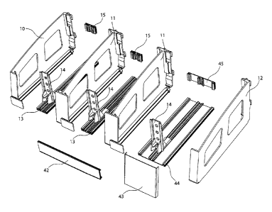
[00128] FIG. 7C shows the pusher paddle 14 which may have an outer paddle face
30, an inner paddle
face 31, an upper paddle section 22 and/or the product angler 33. In an
embodiment, the pusher paddle 14
may be sized and/or configured to be utilized with tall retail products, such
as, for example, tooth brushes
or other oral hygiene products. A height of the pusher paddle 14 may be
customizable by removing the
upper paddle section 32 from the pusher paddle 14. In an embodiment, the
pusher paddle 14 may be
made from a hard plastic material. The hard plastic material may be high
impact styrene, another hard
plastic material or a combination thereof. It should be understood that the
present disclosure is not
limited to a specific embodiment of the hard plastic material of the pusher
paddle 14.
[00129] The outer paddle face 30 may be configured to face, contact and/or
pusher the first and second
products 300, 301. The inner paddle face 31 may be configured to allow first
and second products 300,
301, which may be oddly-shaped products, to recess or sink into the inner
paddle face 31. As a result, the
first and second products 300, 301 may be configured and/or aligned parallel
or substantially parallel to
the product retaining fence 16 and/or the fence inserts 43. In an embodiment,
the upper paddle section 32
may be removably attached to the pusher paddle 14 or may be excluded from the
pusher paddle 14. As a
result, the pusher paddle 14 may be sized and configured to be utilized with
smaller and/or shorter
products. In an embodiment, the product angler 33 may be sized and/or
configured to place, hold and/or
support the first and second products 300, 301 at angle of one or more
degrees. For example, the product
angler 33 may hold the first and second products at an angle of about five
degrees, about ten degrees,
about twenty degrees and/or about thirty degrees. As a result, the first and
second products 300, 301,
which may or may not have irregular package shapes, may track parallel or
substantially parallel to the
pusher paddle 14, the product retaining fence 16 and/or the fence inserts 43
while being moved and/or
pushed along the first and/or second connection plates 13, 44. Moreover, the
product angler 33 may
prevent or substantially prevent irregular shaped packages from becoming
jammed, logged and/or stuck
between adjacent packages and the walls of the dividers 10, 11, 12.
1001301FIG. 8A shows the hanging mount bracket 34 may have a lower track 35
and an upper track 36
which may be sized and/or configured to connect, secure, attach and/or fasten
to the upper rear mounting
hanger 23 and the lower rear mounting hanger 24 on the dividers 10,11,12. As a
result, the dividers 10,
11, 12 may be secured when mounting to the board 151, the upright 150 and/or
the like. The dividers 10,
11, 12 may be configured to slide or move horizontally or substantially
horizontally along the lower
and/or upper tracks 35, 36 to facilitate disconnection and reconnection of the
dividers 10, 11, 12 and the
first and/or second connection plates 13, 44 when reconfiguring sizing and/or
spacing of the pockets 200,
201, 202. The hanging mount bracket 34 may have an inner clip rail 37 and a
crossbar track 38 which
CA 02848791 2014-04-11
-22-
may be utilized to connect, secure, attach and/or fasten to the upright mount
cross bar 39 for mounting to,
for example, the upright 150.
[00131] FIG. 8B shows the upright mount cross bar 39 may have a width
adjustment bracket 40 and a
depth selector plate 41. The width adjustment bracket 40 may be sized and/or
configured to allow the
upright mount cross bar 39 to be connected, attached, fastened, secured,
mounted to uprights with varying
widths. The depth selector plate 41 may be configured for setting a distance
of the dividers 10, 11, 12
from a section of, for example, the upright 150 so that fronts of the dividers
10, 11, 12 are in-line with
adjacent aisle shelves and/or fixtures. As a result, the fronts of the
dividers 10, 11, 12 may be set to be in-
line with an adjacent shelf, such as, for example, a twelve inch, a fourteen
inch or a sixteen inch shelf.
[00132] In an embodiment, the upright cross bar 39 may be made of a hard
material, such as, for example,
hard plastic, steel or a combination thereof. In an embodiment, the upright
cross bar 39 may have a centre
bar, which may mount to the hanging bracket 34, configured to slide forward
and backward along two
side rails. As a result, the divider system 5 may be pulled forward, out from
underneath, for example, the
first shelf 152 above to facilitate quicker and easier loading of the first
and second products 300, 301 into
the pockets 200, 201, 202 of the divider system 5. The movable and/or slidable
centre bar of the upright
cross bar 39 allows a depth associated with the front-side of the divider
system 5 to be adjustable such
that the front-side of the divider system 5 may be aligned with the adjacent
aisle shelves and/or fixtures.
The movable and/or slidable centre bar of the upright cross bar 39 is further
depicted as adjustable depth
merchandising cross bar 2100 as shown in FIGS. 51A, 52, 53A-53C, 54A, 54B and
55. The present
disclosure should not be deemed as limited to a specific embodiment of the
hard material of the upright
cross bar 39.
1001331FIG. 8C shows a peg clip 46 which may be configured to be used to
connect, attach, secure,
fasten and/or mount the hanging mount bracket 34 of the divider system 5 to,
for example, the board 151.
In an embodiment, the peg clip 46 may be, for example, a moulded polycarbonate
clip. In an
embodiment, the board 151 may be, for example, a pegboard or a slatwall. The
present disclosure should
not be deemed as limited to a specific embodiment of the peg clip 46 and/or
the board 151.
1001341FIGS. 9A and 9B shows the front shelf mount track 47 and the rear mount
track 48 which may
have mounting clips 49 formed and/or provided thereon. The dividing system 5
may be mounted to, for
example, the first shelf 152 or the second shelf 153 via the front shelf mount
track 47, the rear mount
track 48 and/or one or more fasteners (not shown in the drawings). The one or
more fasteners may be
screws, bolts, pushpins, adhesive tapes and/or the like. In an embodiment, the
front shelf mount track 47
CA 02848791 2014-04-11
-23-
and/or the rear mount track 48 may be made of plastic material, such as, for
example, extruded plastic
material. It should be understood that the present description should not be
deemed as limited to a
specific embodiment of the one or more fasteners and/or the plastic material
of the front and rear mount
tracks 47, 48.
[00135] In embodiments, the front shelf mount track 47 may be sized and/or
configured to connect, attach,
secure, fasten and/or mount to a conventional retail shelf (not shown in the
drawings) via the toe clip 22
on dividers 10, 11, 12 such that the toe clip 22 may lock, secure and/or
fasten into the front shelf mount
track 47. As a result, the dividers 10, 11, 12 may be connected, attached,
secured, fastened and/or
mounted to the shelf. The rear mount track 48, when mounting to the first
shelf 152 or the second shelf
153, may be mounted with a horizontal flange facing forward for the second
shelf 153 or facing
backwards for the first shelf 152. The mounting clips 49 on rear mount track
48 may be sized and/or
configured to engage the lower rear mounting hanger 24 on the dividers 10, 11,
12. As a result, the
dividers 10, 11, 12 may be connected, attached, mounted, fastened and/or
secured to the rear mount track
48 via the mounting clips 49.
[00136] FIG. 10A shows more than one of the first products 300 which may be
held forward against the
product alignment ribs 19 and/or the front fence 16 at, for example, more than
one degree angle back,
under tension and/or force delivered from the pusher paddle 14, the product
angler 33 and/or the pusher
spring or pusher mechanism. FIG. 10B shows a front most first product 300
which may be removed,
upwards and/or at a forward angle, from the divider system 5. In an
embodiment, the back angle, which
may be about ten degrees, may facilitate forward movement or sliding of the
next first product 300 behind
the front most first product 300. The back angle may also facilitate the
removal of the front most first
product 300 from the divider system 5 without catching or grabbing the first
product 300 behind the front
most first product 300. As a result, the back angle may prevent or
substantially prevent additional first
products 300 from being accidently removed from the divider system 5. Once the
front most first product
300 may clear a top of the front fence 16, remaining first products 300 behind
the front most first product
300 may be moved and/or pushed forward by the pusher paddle 14. The first
products 300 may be
aligned parallel or substantially parallel to the front fence 16 as the first
products may move forward via
the product alignment ribs 19.
[00137] In FIG. 11, the divider system 5 may be connected, attached, secured
and/or fastened to the
hanging mount bracket 34 and/or the clip 46 for mounting the divider system 5
to, for example, the board
151. The divider system 5 may be connected, attached, secured and/or fastened
to the hanging mount
bracket 34 via the upper rear mounting hanger 23, the lower rear mounting
hanger 24, the track 35 and/or
CA 02848791 2014-04-11
-24-
track 36. The hanging mount bracket 34 may be connected, attached, secured
and/or fastened to the clip
46 via the clip attachment rail 37.
[00138] In FIG. 12, the divider system 5 may be connected, attached, secured
and/or fastened to the
hanging mount bracket 34, the upright mount cross bar 39 and/or the depth
selector plate for mounting the
divider system 5 to, for example, the upright 150. The divider system 5 may be
connected, attached,
secured and/or fastened to the hanging mount bracket 34 via the upper rear
mounting hanger 23, the lower
rear mounting hanger 24, the track 35 and/or track 36. The hanging mount
bracket 34 may be connected,
attached, secured and/or fastened to the upright mount cross bar 39 and/or the
depth selector plate via the
track 38.
[00139] In FIG. 13A, the divider system 5 may be connected, attached, secured,
fastened and/or mounted
to the second shelf 153 via the lower rear mounting hanger 24, the front shelf
mount track 47, the rear
mount track 48 and/or mounting clips 49. When mounting the divider system 5
onto the second shelf
153, one or more toe clips 22 of the dividers 10, 11, 12 may be inserted at a
forward angle into the front
shelf mount track 47. A back of the divider system 5 may be subsequently
lowered onto the rear shelf
mount track 48 and the lower rear mounting hanger 24 may connect with and/or
engage the mounting
track 49 to provide a secure fit.
[00140] In FIG. 13B, the divider system 5 may be connected attached, secured,
fastened and/or mounted
to the first shelf 152 via the lower rear mounting hanger 24, the rear mount
track 48 and/or mounting clips
49. When mounting the divider system 5 onto the first shelf 153, positioning
of the rear shelf mount track
48 may be flipped, moved, rotated to situate and/or align front edges of the
dividers 10, 11, 12 with a
front edge of the first shelf 152.
[00141] FIG. 14 shows multiple divider system configurations for more than one
divider system 204
which may be utilized for mounting divider systems 5 to different mounting
components. The divider
system 204 may have the same or similar features and/or components as the
divider system 5 and the
features and/or components of the divider system 204 may operate and/or
function in the same or similar
manner as the features and components of the divider system 5. A first divider
system configuration 250
facilities mounting of the divider system 204 to the board 151, a second
divider system configuration 251
facilitates mounting the divider system 204 to the uprights 150, a third
divider system configuration 252
facilitates mounting the divider system 204 to the first shelf 152, and a
forth divider system configuration
253 facilitates mounting the divider system 204 to the uprights 150 and an
adjustable depth
merchandising crossbar 154 (hereinafter "adjustable crossbar 154"). In
embodiments, a typical retail
CA 02848791 2014-04-11
-25-
gondola section 400 (hereinafter "gondola section 400") may comprise the board
151, the uprights 150
and/or the first shelf 152.
[00142] The adjustable crossbar 154 is configured such that the divider system
204, mounted thereon,
may slide or move inwardly or outwardly with respect to the uprights 150, the
board 151 and/or the
gondola section 400. As a result, the divider system 204 may be pushed inward
or pull outward with
respect to the uprights 150, the board 151 and/or the gondola section 400 via
the adjustable crossbar 154.
The divider system 204 may be pulled outward to a partially expanded depth or
a fully extended depth for
loading, reloading or positioning the products 300, 301 in the pockets 200,
201, respectively. The depth
of the divider system 204 may be adjusted, via the adjustable crossbar 154
such that the front-side the
divider system 204, mounted on the adjustable crossbar 154, aligns flush with
the front-sides of the other
divider system 204 mounted to the uprights 150, the board 151 and/or the shelf
152 and/or with the front-
sides of surrounding or adjacent shelving and/or displays. In embodiments, the
adjustable crossbar 154
may be connected, attached, secured, fastened and/or mounted to divider system
204 via the upper rear
mounting hanger 23 and/or the lower rear mounting hanger 24,
[00143] In embodiments, the divider system 204 may have a width of, for
example about twelve inches,
about twenty-four inches, about forty-eight inches or about sixty inches. The
divider system 204 may
have any number of pockets 200, 201, 202 as known to one of ordinary skill in
the art. For example, the
divider system 204 may have nine of the pockets 202 and fourteen of the
pockets 200. It should
understood that the present disclosure should not be deemed as limited to a
specific embodiment of the
width of the divider system 204 and/or number of pockets 200, 201, 202.
1001441 The divider system configuration 250 is also shown in FIGS. 11, 14 and
15 and may be utilized to
connect, attach, secure, fasten and/or mount the divider system 204 to a
slatwall (not shown in the
drawings). The divider system configuration 251 is also shown in FIGS. 12, 14
and 16. The divider
system configuration 252 is also shown in FIGS. 13, 14 and 17.
[00145] FIG. 15 shows the divider system configuration 250 having the divider
system 204 which may be
connected, attached, secured, fastened and/or mounted to the board 151 via
clips 46 and/or hanging mount
bracket 34. Any width of the divider system 204 may be used when utilizing
configuration 250. Hanging
mount bracket 34 may be cut to the necessary and/or required width to hold the
number of dividers 10,
11, 13 and/or pockets 200, 201, 202 as required. This is the same advantage
realized when mounting
divider system 204 to the upright 150, the first shelf 152 and/or the second
shelf 153 and utilizing the
configuration 250.
CA 02848791 2014-04-11
-26-
[00146] FIG. 16 shows the divider system configuration 251 having the divider
system 204 which may be
connected, attached, secured, fastened and/or mount to the upright 150 via the
hanging mount bracket 34
and/or the upright mount cross bar 39. FIG. 17. Shows the divider system
configuration 252 having the
divider system 204 which may be connected, attached, secured, fastened and/or
mount to the first or
second shelves 152, 153 via the front shelf mount track 47 and/or the rear
mount track 48.
[00147] The divider systems 5, 204 may combine the versatility and flexibility
of peg hooks with benefits
of automatic facing and clean, high-end look of on-shelf pusher systems.
[00148] The divider systems 5, 204 may provide retailers the ability to
merchandise small, lightweight or
oddly shaped products while preventing or substantially preventing fallen
and/or broken packages along
with constant upkeep.
[00149] The divider system 5, 204 may be utilized with, for example, oral
hygiene, pharmacy and beauty
products, as well as other such products which may be traditionally
merchandised on hooks, but may also
be adapted to fit any retail product.
[00150] FIG. 18 shows an exploded perspective view of a quick-load pusher
system 1000 (hereinafter
"pusher system 1000") in an embodiment. The pusher system 1000 may comprise
one or more of a pusher
track 1010, a hanging gusset 1011, a data track component 1012, a front plate
1013, wire dividers 1014, a
pusher paddle 1015 and/or a bar mount bracket 1016. The pusher system 1000 may
be sized and/or
configured to store, house, secure, display, enclose and/or dispense one or
more products 3300
(hereinafter "products 3300"). The pusher system 1000 may have one or more
features and/or
components that may be the same as or similar to the features and/or
components of the divider systems
5, 204. Moreover, the features and/or components of the pusher system 1000 may
operate and/or function
in a same or similar manner as the features and/or components of the divider
systems 5, 204.
[00151] In an embodiment, the products 3300 may be, for example, bagged
products, such as, for
example, bagged cheese, bagged salad, bagged deli meats and/or the like. In
embodiments, the products
3300 may by, for example, consumer products, food products, hard goods,
durable goods, soft goods,
consumables, consumer-grade goods, professional-grade goods and/or the like.
In embodiments, the
products 3300 may be OTC products, such as, for example, analgesics,
medications, pharmaceuticals,
razors, razor blades, camera film, batteries, videos, DVDs, smoking cessation
products, infant formula,
vitamins, personal care products, home care products, toothbrushes,
foodstuffs, packaged foods, kitchen
supplies, bags, boxes, containers and/or the like. In an embodiment, the
products 3300 may be the same
or similar retail products as the first and second products 300, 301. It
should be understood that the
CA 02848791 2014-04-11
-27-
present disclosure is not deemed as limited to a specific embodiment of the
bagged products, OTC
products and/or the one or more products 3300.
[001521The pusher track 1010 may be sized and/or configured to hold, support
and/or display the product
3300 and/or may slide and/or pull out for product loading of the pusher system
1010. The pusher track
1010 may be connected, attached, fastened, secured and/or mounted to the
hanging gusset 1011 and may
move, glide and/or slide along the hanging gusset 1011 when the pusher track
1010 is being loaded. The
pusher track 1010 may be connected, attached, secured, fastened and/or mounted
to one or more of the
data track component 1012, the front plate 1013, the wire dividers 1014, the
pusher paddle 1015 and/or
the bar mount bracket 1016 (as shown in FIG. 19).
=
[001531The hanging gusset 1011 may support the pusher track 1010 and may allow
the pusher track 1010
to slide inward and outward for product loading and displaying the first and
second products 300, 301 or
the products 3300. The hanging gusset 1011 may be connected, attached,
secured, fastened and/or
mounted to the bar mount bracket 1016 to allow the hanging gusset 1011 to
connect, attach, hang, secure
and/or fasten to a crossbar 403 (as shown in FIG. 31). In an embodiment, the
hanging gusset 1011 may
connect, attached, fasten, secure and/or mount to a peg mount 1030 to allow
the hanging gusset 1011 to
connect, attach, fasten and/or hang to the peg board 400 (as shown in FIG.
32). The hanging gusset 1011
may prevent, substantially prevent and/or restrict forward movement of the
pusher paddle 1015 via one or
more pusher track stoppers 1033 (as shown in FIG. 22). The hanging gusset 1011
may prevent,
substantially prevent and/or restrict forward movement of the pusher track
1010 via one or more middle
stoppers (not shown in the drawings) and/or one or more rear plates (not shown
in the drawings).
[00154] The data track component 1012 may hold, support and/or display product
information indicative
of one or more of the products 3300. The data track component 1012 may attach,
connect, snap, fasten,
secure and/or mount to the pusher track 1010 and/or the wire dividers 1014. In
an embodiment, the data
track component may be sized and/or configured to allow an alternate
installation arrangement for the
pusher track 1010 via compatibility with a snap track.
[00155] The front plate 1013 may be, for example, a customer facing front
barrier for products 302 and/or
may restrict movement of the products 3300 forward toward a front-side of the
pusher system 1000. The
front plate 1013 may connect, attach, secure and/or fasten to a front side of
the pusher track 1010. In an
embodiment, the front plate 1013 may be transparent and/or interchangeable
with additional front plates
(not shown in the drawings).
CA 02848791 2014-04-11
-28-
[00156] The wire dividers 1014 may be, for example, an adjustable horizontal
barrier for holding retail
products, such as, for example, the products 3300. The wire dividers 1014 may
be connected, attached,
fastened, secured and/or mounted to pusher track 1010 at one or more rear tube
mounts 1017 of the
pusher track 1010 (as shown in FIG. 21). As a result, the wire dividers 1014
may be aligned parallel or
substantially parallel to each other. The wire dividers 1014 may move, extend,
retract and/or slide
horizontally or substantially horizontally through the rear tube mounts 1017of
the pusher track 1010
which may allow for telescoping adjustability of the wire dividers 1014. The
wire dividers 1014 may
connect, attach, secure, fasten and/or mount to the data track component 1012
via tube mounts 136 of the
data track component 1012 (as shown in FIG. 28A), The wire dividers 1014 may
move, extend, retract
and/or slide horizontally or substantially horizontally through the tube
mounts 136 which may allow for
telescoping adjustability of the wire dividers 1012. In embodiments, the wire
dividers 1012 may be, for
example, painted and/or plated wire dividers.
[00157] The pusher paddle 1015 may be sized and/or configured to provide
and/or apply a pressure, a
force or a constant pressure against the first and second products 300, 301 or
the products 3300 which
may be contained and/or stored within the pusher system 1000. As a result, the
first and second products
300, 301 or the products 3300 may be forced, pressured and/or squeezed between
the pusher paddle 1015
and the front plate 1013. The pusher paddle 1015 may connect, attach, secure
and/or fasten to and/or
snap into the pusher plate 1010 and/or may move or slide lengthwise along one
or more grooves in the
pusher plate 1010. In embodiments, the pusher paddle 1015 may have the same
features and components
as the pusher paddle 14 which may function and/or operate in the same or
similar manner as the features
and/or components of the pusher paddle 14.
[00158] The bar mount bracket 1016 may connect, attach, secure, fasten and/or
mount to a rear of the
hanging gusset 1011. The bar mount bracket 1016 may have one or more
fasteners, such as, for example,
one or more hooks which may attach, connect, secure, fasten and/or hook the
bar mount bracket to the
crossbar 403. As a result, the pusher system 1000 may connect, attach, fasten,
secure and mount to the
crossbar 403 via the bar mount bracket 1016.
[00159] In embodiments, one or more the pusher track 1010, the data track
component 1012, the front
plate 1013, the pusher paddle 115 and/or the bar mount bracket 1016 may be
made of a plastic material
and/or a moulded plastic material. The plastic material and/or the moulded
plastic material may be, for
example, a clear plastic material or a non-clear plastic material.
CA 02848791 2014-04-11
-29-
[00160] FIG. 19 shows a pusher system configuration 5151 having the pusher
system 1000 in a fully
assembled state. In an embodiment, the pusher system 1000 may be storing,
holding, securing and/or
displaying one or more products 3300 which may be forced, pressured and/or
squeezed between the
pusher paddle 1015 and the front plate 1013 via a pusher spring and/or a
pusher mechanism, such as, for
example, a clock-type spring (not shown). The wire dividers 1014 may be moved,
retracted and/or slid
together or inward with respect to each other to accommodate an approximate
width of the one or more
products 3300. The bar mount bracket 1016 may be utilized in the pusher system
configuration 5151
such that the pusher system 1000 may be connected, attached, fastened, secured
and/or mounted to the
crossbar 403. The pusher system 1000 may have a snap track 1037 which may
connect, attach, secure
and/or snap into a snap clip 1023 on the pusher track 1010.
[00161] FIG. 20 shows an elevated front perspective view of the pusher system
1000. The wire dividers
1014 may be installed into the rear tube mounts 1017 and/or the tube mounts
1036 of the pusher track
1010. The wire dividers 1014 may be configured to telescope outward and/or to
retract inward to change
and/or adjust a distance or width between the wire dividers 1014. As a result,
the distance or width
between the wire dividers 1014 may be changed and/or adjusted to receive one
or more of the products
3300 and/or to correspond to a width associated with the one or more products
3300.
[00162] FIG. 21 shows a top side of the pusher track 1010, whereby the pusher
track 1010 may be sized
and/or configured to move, extend, retract and/or forward and back via a
pusher track rail 1022 when the
hanging gusset 1011 is not being utilized. This may be accomplished by
mounting the pusher track 1010
to other parts and/or components which may allow the pusher track 1010 to be
used on other fixtures,
such as, for example, a first or second shelf 152, 153 by incorporating a
similar interface to relevant
features of the pusher system 1000. The pusher track 1010 may have one or more
rear tube mounts 1117
which may be sized and/or configured to guide and/or assist the wire dividers
1014 along their
telescoping path. The pusher track 1010 may have one or more main pusher
paddle grooves 1019 which
may be sized and/or configured to allow the pusher paddle 1015 to connect,
attach, secure, fasten and/or
mount to the pusher track 1010 and to move and/or slide along a length of
pusher track 1010. The pusher
track 1010 may have one or more front dovetail tabs 1020 which may be sized
and/or configured to create
a tight frictional interface and precise registration by the connection of the
front dovetail tabs 1020 with
interchangeable front plate 1013. The pusher track 1010 may have one or more
front windows 1021
which may be sized and/or configured such that the wire dividers 1014 may pass
through pusher track
1010 and/or may access the tube mounts 1036 on the data track component 1012.
The pusher track 1010
may have one or more pusher track rails 1022 which may be sized and/or
configured to allow the pusher
track 1010 to move, extend, retract and/or slide longitudinally on the hanging
gusset 1011 such that side-
CA 02848791 2014-04-11
-30-
to-side motion and/or up-and-down motion may be controllable. The pusher track
1010 may have one or
more snap clips 1023 which may connect, attach, secure, fasten and/or snap
onto a snap track on the data
track component 1012. The pusher track 1010 may have one or more pusher track
terminus 1048 which
may be sized and/or configured to be a rear limit to linear motion of and/or
on the pusher track 1010. In
an embodiment, the push track terminus 1048 may be sized and/or configured to
physically interface with
a rear gusset wall 1034 of the hanging gusset 1011.
[00163] In FIG. 22, a bottom side the pusher track 1010 may have one or more
bottom extrusion teeth
1032 which may be sized and/or configured to be utilized as a hook interface
and/or hook mechanism
with an end return 1038 of the data track component 1012. The pusher track
1010 may have one or more
pusher track stoppers 1033 which may be sized and/or configured to restrict,
prevent and/or limit forward
movement of the pusher track 1010 on the hanging gusset 1011 through, for
example, physical interface
with a gusset ramp 1029 of the hanging gusset 1011. The pusher track 1010 may
have one or more
accessory mounts 1045 which may be sized and/or configured for mounting one or
more peripheral
accessories for alternate assemblies.
[00164] FIG. 23 shows a top perspective view of the hanging gusset 1011 which
may have one or more
front retainer teeth 1024 which may be sized and/or configured to limit
forward movement of the pusher
paddle 1015 and/or to allow release of force and/or pressure between the
pusher paddle 1015, the one or
more products 3300, and the front plate 1013 during product loading and/or
product rotation. For
example, when the pusher track 1010 may pulled outward, the one or more teeth
1024 may force the
pusher paddle 1015 to stay behind or may hold the pusher paddle 1015 from
moving forward with the
pusher track 1010. As a result, a gap may be created, produced and/or formed
between the pusher paddle
1015 and the front plate 1013 which may be utilized for product loading and/or
product rotation.
[00165] The hanging gusset 1011 may have one or more upper gusset teeth 1025
which may be sized
and/or configured to be an upper limit for physical interface between the
pusher track rail 1022 of the
pusher track 1010 and the hanging gusset 1011. The hanging gusset 1011 may
have one or more lower
gusset surfaces 126 which may be sized and/or configured to be a lower limit
of the physical interface
between the pusher track rail 1022 of the pusher track 1010 and the hanging
gusset 1011. In an
embodiment, the lower gusset surfaces 126 may be sized and/or configured to
work along with and/or to
cooperate with the upper gusset teeth 1025 to lock the pusher track rail 1022
into a sliding path for the
pusher track rail 1022. As a result, the pusher track rail 1022 may be locked,
secured and/or fastened into
the sliding path via the upper gusset teeth 1025 and/or the lower gusset
surfaces 126. The hanging gusset
1011 may have one or more rear gusset hooks 1028, which may be sized and/or
configured to wrap
CA 02848791 2014-04-11
-31 -
around a top of the bar mount bracket 1016. As a result, an assembly of the
pusher track 1010 and the
hanging gusset may be stiffened and/or strengthened and/or made to be more
rigid via the rear gusset
hooks 1028 and/or the top of the bar mount bracket 1016. The hanging gusset
1011 may have one or
more rear gusset wall 1034 which may be sized and/or configured to be a
rearward limit to the linear
motion of and/or on the pusher track 1010.
[001661FIG. 24 shows a bottom side of the hanging gusset 1011 having one or
more rear vertical slots
1027 which may be sized and/or configured to be a female interface between the
hanging gusset 1011 and
a vertical bracket track 1040 on bar mount bracket 1016 and/or peg mount
bracket 1030 (as shown in
FIG. 29A and 29B). The hanging gusset 1011 may have one or more baffle mounts
1031 which may be
sized and/or configured to be one or more mounting points for hardware which
may hold the horizontal
baffle in place, used to facilitate directional airflow within a refrigerated
environment (not shown in
drawings). The hanging gusset 1011 may have one or more stiffening structure
1044 which may be sized
and/or configured to increase stiffness of the hanging gusset 1011 and/or to
airflow through the assembly
of the pusher track 1010 and the hanging gusset 1011, with or without the use
of the above mentioned
baffle.
[001671FIG. 25A and 25B show a pusher system configuration 5151 having the
pusher system 1000 in a
closed position and an open position, respectively. The pusher track 1010 may
have the one or more
pusher track rails 1022 which may be rails or lips along left and right sides
of the pusher track 1010. The
pusher track rails may slide between the upper gusset teeth 1025 and the lower
gusset surface 1026 on
hanging gusset 1011 which may control the pusher track 1010 front-to-back
movements and side-to-side
movements.
[0016810nce the pusher system 1000 may be assembled, the pusher system 1000
may be configured to
allow the pusher track 1010 to move, extend, retract and/or slide
longitudinally within and/or between a
front limit and a rear limit of the pusher system 1000. The front limit may be
dictated, formed, created
and/or produced by one or more gusset ramps 1029 of the hanging gusset 1011,
and the rear limit may be
dictated, formed, created and/or produced by the rear gusset wall 1034 of the
hanging gusset 1011.
Moreover, forward longitudinal movement of the pusher paddle 1015 may be
control, prevented and/or
allowed via the front retainer teeth 1024 of the hanging gusset 1011. The
gusset ramp 1029 may be sized
and/or configured to be a locking mechanism between the pusher track 1010 and
the hanging gusset 1011
and/or to limit forward movement of the pusher track 1010 on the hanging
gusset 1011 through, for
example, physical interface with the pusher track stopper 1033 of the hanging
gusset 1011.
CA 02848791 2014-04-11
-32-
[00169] One purpose of this independent component retention may be, for
example, to allow the pusher
paddle 1015 to maintain contact pressure with the one or more products 3300
which may be within the
pusher system 1000 while the pusher system 1000 may be in the closed position
(see FIG. 25A), and/or to
release the pressure when the pusher system 1000 may be in the opened position
(see FIG. 25B). As a
result, a gap may be created, formed, produced and/or provided between any
remaining products 3300
within the pusher system 1000 and the pusher paddle 1015 so that new or
additional products 3300 may
be placed into the pusher system 1000 behind any previous or remaining
products 3300.
[00170] FIG. 25A shows the pusher track 1010 may move and/or slide to a point
where the pusher track
terminus 1048 may make contact with the rear gusset wall 1034. As a result,
the rearward motion of the
pusher track 1010 may be limited by the pusher track terminus 1048 and/or the
rear gusset wall 1034. In
an embodiment, the pusher paddle 1015 may make contact with the front retainer
teeth 1024 and force
and/or pressure applied by the pusher spring may hold the pusher paddle 1015
against the front retainer
teeth 1024 when, for example, there is no product 302 in the pusher system
1000.
[00171] FIG. 25B shows the pusher track 1010 may extend to a point where the
pusher track stopper 1033
may be in contact with the gusset ramp 1029 which may stop the pusher track
1010 from sliding forward
to any further point. The pusher paddle 1015 may remain pulled firmly against
the front retainer teeth
1024 with the pusher spring in a further extended position than in FIG. 25A.
In an embodiment, the
pusher track rail 1022 may remain confined between the upper gusset teeth 1025
and the lower gusset
surface 1026 which may provide support for this increased cantilever form.
[00172] FIG. 26 shows a cross-sectional view of the assembly of the pusher
track 1010 and the hanging
gusset 1011 and any interactions, at the front-side of the pusher system 1000,
between the pusher track
1010 and the hanging gusset 1011. For example, a data track slot 1047 may be
located or sandwiched
between two front walls of data track component 1012. The data track slot may
be sized and/or
configured to hold a product information strip. In an embodiment, the pusher
system 1000 may have
frictional interfaces between the snap clip 1023 on the pusher track 1010 and
a snap track 1037 on the
data track component 1012. The extrusion snap track 1037 may be sized and/or
configured to connect,
attach, secure and/or snaps into the snap clip 1023 on the pusher track 1010.
In an embodiment, the
pusher system 1000 may have contact interface between an end return 1038 on
the data track component
1012 and the bottom extrusion teeth 1032 on the pusher track 1010. The end
return 1038 may be sized
and/or configured to be a hook interface or hook mechanism with the bottom
extrusion teeth 1032.
CA 02848791 2014-04-11
-33-
[00173] At early stages of the assembly of the pusher system 1000, the data
track component 1012 may be
installed onto the pusher track 1010 which may be accomplished and/or achieved
in a pivoting manner,
where, for example, the contact interface between the pusher tracker 1010 and
the data track component
1012 may be created first. For example, data track component 1012 may be
angled below the pusher
track 1010, and may then be swung upward which may pivot on the contact point
and/or may engage the
frictional interface between the snap clip 1023 on the pusher track 1010 and
the snap track 1037 on the
data track component 1012.
[00174] FIG. 27 shows a front cross-sectional view the pusher system 1000
which shows the pusher track
1010, the hanging gusset 1011 and the pusher paddle 1015. FIG. 27 also
illustrates two front-to-back,
track-like interfaces which may be provided by the pusher system 1000. For
example, lower legs of the
pusher paddle 1015 may connect, attach, secure, fasten and/or hook around
track slots 1019 which may
prevent, restrict and/or limit up-and-down movements of the pusher paddle 1015
while allowing the
pusher paddle 1015 to move, extend, retract and/or slide forward and backwards
with respect to the front-
side of the pusher system 1000. In an embodiment, both left and right pusher
track rails 1022 may be
located or sandwiched between the upper gusset teeth 1025 and the lower gusset
surface 1026, whereby a
=
tolerance between these components may allow them to move freely along a
central axis of the pusher
system 1000.
[00175] FIG. 28A shows a perspective view of the data track component 1012
having one or more bar
hook 1035 which may be sized and/or configured to connect, attach, secure,
fasten and/or hook over the
crossbar 403 to supporting the pusher system 1000. The data track component
1012 may have one or
more extruded tube mounts 1036 which may be sized and/or configured to guide
and/or assist the wire
dividers 1014 along the telescoping path of the wire dividers 1014. The data
track component 1012 may
have one or more snap clip 1046 which may be sized and/or configured to
connect, attach, fasten, secure
and/or snap onto a peripheral snap track on alternate assemblies.
[00176] FIG. 28B shows a perspective view of the front plate 1013 having one
or more female dovetail
tabs 1041 which may be sized and/or configured to be a tight frictional
interface and/or precise
registration creatable by connection of the female dovetail tabs 1041 and the
male dovetail tabs 1020 on
the pusher track 1010. The front plate 1013 may have one or more interfaces
1042 which may be sized
and/or configured to interface, cooperate and/or corresponding with a
stiffening cavity 1050 on the pusher
track 1010. The front plate 1013 may have one or more terminal surface 1043
which may be sized and/or
configured to be a forward limit for the products 3300 which may be pushed
forward by the pusher paddle
1015.
CA 02848791 2014-04-11
-34-
[00177] FIG. 29A shows a peg mount bracket 1030 which may be sized and/or
configured to connect,
attach, secure, fasten and/or mount to a rear of the hanging gusset 1011. The
peg mount bracket 1030
may connect, attach, secure, fasten and/or hook onto a peg board 400 to hang
the pusher system 1000
from the peg board 400. In an embodiment, the peg board 400 may be, for
example, a vertical pegboard
and/or may have one or more holes which may be spaced about one inch from one
another. It should be
understood that the present disclosure should not be deemed as limited to a
specific embodiment of
pegboard.
[00178] The peg mount bracket 1030 may have one more peg hooks 139 which may
be sized and/or
configured to be inserted into the peg board 400 to support the pusher system
1000. The peg mount
bracket 1030 may have one or more vertical bracket tracks 1040 which may be
sized and/or configured to
be male interfaces between the bar mount bracket 1016, the peg mount bracket
1030 and/or the hanging
gusset 1011.
[00179] FIG. 298 shows a bar mount bracket 1016 having one or more vertical
bracket tracks 1040 and/or
one or more bar hooks 1035 for supporting the pusher system 1000.
[00180] FIGS. 30A shows pusher system configuration 5150 having the pusher
system 1000 and the peg
mount bracket 1030. In the pusher system configuration 5150 the rear gusset
hook 1028 may have to be
removed from the hanging gusset 1011 in order to maintain compatibility with
the peg mount bracket
1030 and/or the peg board 400.
[00181] FIG. 30B shows pusher system configuration 5151 having the pusher
system 1000 and the bar
mount 1016 which may also be compatible with the crossbar 403.
[00182] FIG. 31 shows the pusher system configuration 5151 as it may appear in
a retail environment. In
an embodiment, a number of pusher systems 1000 may be connected, attach,
secured, fastened and/or
mount to, for example, a number of cross bars 403. For example, two pusher
systems 1000 may be hung
on each of three cross bars 403 which may, in turn, be inserted into two
upright 402. For example, one or
more pusher systems 1000 may be installed in series along one or more
crossbars of varying lengths
which may create a shelf-like presentation for the first and second products
300, 301 or the products
3300. Vertical distance(s) between each row of pusher systems 1000 may be
changed and/or adjusted to
suit the first and second products 300, 301 or the products 3300 which may
have varying heights and/or
sizes by adjusting vertical positioning of the cross bars 403 along the
uprights 402. In an embodiment,
the pusher system configuration 5151 and/or the pusher systems 1000 may be
utilized in, for example, a
common retail environment, such as, for example, aisles, refrigerators and/or
the like.
CA 02848791 2014-04-11
-35-
[001831FIG. 32 shows the pusher system configuration 5150 as it may appear in
a retail environment. In
an embodiment, the pusher system configuration 5150 may have one or more
pusher systems 1000 which
may be connected, attached, secured, fastened and/or mounted to the peg board
400. For example, the
pusher system configuration 5150 may have six pusher systems 1000 which may be
hung on a section of
the peg board 400. FIG. 32 illustrates that one or more pusher system 1000 may
be installed in a myriad
of planar arrangements on the peg board 400. Vertical and horizontal distances
between the pusher
systems 1000 may be changed and/or adjusted by moving and/or altering an
arrangement of the peg board
brackets 30 of the pusher systems 1000 on the peg board 400.
1001841FIG. 33 shows a variety of the pusher systems 1000 having a variety of
different lengths. In order
to accomplish the variations in length, the pusher tracks 1010 and the hanging
gussets 1011 of the pusher
systems 1000 may be injection moulded within a modular mould. By adding
central inserts to the mould,
parts with different lengths may be created, produced and/or formed while
maintaining front and rear
mould components. FIG. 33 shows four sizes available for the pusher systems
1000 along with a number
of inserts which may be needed to create the different lengths.
[00185] In embodiments, the pusher systems 1000 may be comprised of
individual, self-contained product
holders which may eliminate a need for a traditional store shelf and may
increase merchandising
flexibility. The pusher systems 1000 may have an ability to be mounted to a
traditional store shelf but
may excel when mounted to pegboard 400 or a cross bar 403. The pusher track
1010 on which the
products 302 may sit and/or may be positioned may have an ability to pull
forward and out from
underneath the shelf or fixture above. This improves an ease and speed of
loading as a majority of the
pusher track 1010 may be exposed and free from obstruction. Less vertical
space may be required
between product rows which may result in additional product holding power
within the aisle section.
Furthermore, when the pusher track 1010 may be pulled forward for loading, the
pusher paddle 1015 may
remain retracted, and may allow for quick two-handed loading of the products
302 into the pusher
systems 1000. Unlike any other known pull-out system, a majority of components
of the pusher systems
1000 including attachment brackets and structural members may be made from
moulded plastic. Metal
components such as the wire dividers 1014 and/or the pusher spring may be made
from corrosion resistant
metals for use in cold or damp locations such as coolers, fridges and
freezers, drastically reducing the risk
of metal corrosion within a food environment. This also may ensure that moving
mechanical components
may retain consistent and proper function.
1001861As shown in FIGS. 34-50, one or more retail products 3301 (hereinafter
"retail products 3301")
and/or one or more retail products 3302 (hereinafter "retail products 3302")
may be housed, stored,
CA 02848791 2014-04-11
-36-
secured and/or displayed or dispensed from at least one of a quick-load pusher
system 5152 (hereinafter
"pusher system 5152"), a quick-load pusher system 5153 (hereinafter "pusher
system 5153"), a quick-
load pusher system 5154 (hereinafter "pusher system 5154"), a quick-load
pusher system 5154
(hereinafter "pusher system 5154"), a quick-load pusher system 5155
(hereinafter "pusher system 5155")
and/or a quick-load pusher system 5156 (hereinafter "pusher system 5156"),
collectively known
hereinafter as "pusher systems 5152, 5153, 5154, 5155, 5156". The retail
products 3 301 may be, for
example, packaged products, such as, meats and/or cheese which may typically
be merchandised using
hanging hooks, and the retail products 3302 may be, for example, ridged
packaged products, such as,
frozen food packages, boxes, microwave meals which may be merchandised using a
pusher system. In
embodiments, the retail products 3301 and/or the retail products 3302
(collectively know hereinafter as
"retail products 3301, 3302") may be similar to or the same as the first and
second products 300, 301
and/or the retail products 3300.
(00187) The pusher systems 5152, 5153, 5154, 5155, 5156 may be connected,
attached, mounted,
fastened, joined and/or secured to a retail gondola section 405 having aisle
uprights 402, a retail gondola
shelf 406, a back structural lip 407 of the retail gondola shelf 406 or a back
wall 408 of the gondola
section 405 or a refrigerator (not shown in the drawings. In embodiments, the
retail gondola section 405
may be a typical retail gondola section having a width of more than about two
feet, such as, for example,
about four feet, and the shelf 406 may be a typical retail gondola shelf
having a depth of less than about
twenty-four inches, such as, for example, about eighteen inches.
[00188] The pusher systems 5152, 5153, 5154, 5155, 5156 may comprise one or
more of the following
structural features and/or components, which may be connected, attached,
fastened, secured, joined and/or
mounted to each other and/or combinations thereof: a data Track Extrusion
1051; a first moulded air
divider assembly 1052; a second moulded air divider assembly 1053; moulded air
holes 1054; moulded
divider rails 1055; a moulded divider body 1056; guide holes 1057; snap mounts
1058; a wide pusher
paddle 1059; a hanging baffle bar assembly 1060; hanging baffle bar mounting
brackets 1061; a forward
leveling bar 1062; a baffle sheet 1063; a hook grip clip 1064; a Safety flange
1065; a horizontal lip shelf
extrusion 1066; a vertical lip shelf extrusion 1067; a lock slot 1068; forward
tube mounts 1069; in
interchangeable curved front plate 1070; graphic tabs 1071; a modular baffle
1072; Baffle mounting
hardware 1073; a shelf grip mount 1074; a shelf anchor clip 1075; loading lock
tabs 1076; pusher track
retaining clips 1077; loading lock ramps 1078; a moulded snap clip 1079; a
base retainer plate 1080; base
slide rails 1081; base track gripper legs 1082; a base track 1083; an
adjustment Pin 1084; a T-Snap track
1085; a depth adjustment plate 1086; depth holes 1087, 1088; a horizontal
flange 1090; a vertical flange
1091; a friction 0-ring 1092; a loading gap 1093. One or more of the above-
identified structural features
CA 02848791 2014-04-11
-37-
and/or components may be connected, attached, secured, joined and/or mounted
to each other or
combinations thereof to assembly, produce and/or provide one or more of the
pusher systems 5152, 5153,
5154, 5155, 5156 as shown in and illustrated by FIGS. 34-50.
[00189] The data track extrusion 1051 may be connected, attached, fixed,
joined and/or secured to the
front plate 1013 via an adhesive or to the pusher track 1010 via 1023 snap
clip 1023 and/or the extrusion
snap track 1032. The first moulded air divider assembly 1052 may extend
upwardly in the vertical or
substantially vertical direction to provide an adjustable horizontal barrier
for retail product and/or may be
connected, attached, joined, fastened and/or secured to the pusher track 1010
at the front tube mount 1069
and/or the rear tube mount 1017. The second moulded air divider assembly 1053
may extended in the
vertical or substantially vertical direction to provide an adjustable
horizontal barrier for retail product
and/or may be connected, attached, joined, fastened and/or secured to the
pusher track 1010 at the front
tube mount 1069 and/or the rear tube mount 1017.
[00190] The moulded divider body 1056 may be, for example, an L-shaped divider
and/or may provide
support for larger bagged products which may improve functionality of the
systems. The moulded divider
body 1056 may have a solid plastic construction with the air holes 1054 which
may help control, manage
and/or maintain temperatures surrounding the retail products 3302 when the
moulded divider body and
the retail products 3302 are located within a refrigerated environment. The
air holes 1054 may help
control, manage and/or prevent cold air loss by, for example, slowing and/or
channeling cold air
movement between adjacent products and dividers before its eventual release
into the surrounding
environment. The air holes 1054 may be moulded into and/or formed or
positioned within the vertical
sides of the moulded divider body 1056, and the air holes 1054 may help
control, manage and/or prevent
cold air loss by slowing and channeling cold air movement between adjacent
products and dividers before
the cold air may be eventual released into the surrounding environment.
[00191] The moulded divider rails 1055 may be connected, attached and/or
affixed to the moulded divider
body 1056 through the guide holes 1057 and the snap mounts 1058. In an
embodiment, the moulded
divider rails may comprise at least one metal wire and may connect, attach,
fasten or affix to the pusher
track 1010 at the front tube mount 1069 and/or the rear tube mount 1017. The
guide holes 1057 may be
moulded into and/or formed or position on the divider body 1056 to position or
affix the moulded divider
rails 1055 for alignment with connection points on the pusher plate 1010. The
snap mounts 1058 may
fasten, lock or secure the moulded divider rails 1055 to an underside of the
moulded divider body 1056
when connected, attached and/or mounted in the guide holes 1057. The friction
0-ring 1092 may be
formed, provided and/or located on the moulded divider rails 1055. In an
embodiment, the parallel wire
CA 02848791 2014-04-11
-38-
divider 1014 and/or the friction 0-ring 1092 may be provided, positioned
and/or located within the
underside of pusher plate 1010 in the front and rear tube mounts 1069, 1017
which may increase friction
and/or may slow horizontal movement of the connected or attached moulded
divider bodies 1056.
1001921The wide pusher paddle 1059 is a variation of pusher paddle 1015 for
use with wide or heady
products, such as, for example, the retail product 3301 to vertically or
substantially vertically support the
wide or heady products and/or to provide or exert forward pressure against the
retail products 3301, 3302.
The hanging baffle bar assembly 1060 may replaces modular baffle 1072 in a
refrigerated environment
when a row of the pusher systems 5152, 5153, 5154, 5155, 5156 may be used. The
1061 hanging baffle
bar mounting brackets 1061 may connect, attach, affix and/or mount the hanging
baffle bar 160 to the
crossbar 403. The forward leveling bar 1062 may be utilized with the divider
system 5 such that the
divider system 5 may vertically settle when weight of the retail products,
such as, the first and second
products 300, 301 may be applied thereon. In embodiments, different retail
products of varying weight
(i.e., the first and second products 300, 301) may be merchandised adjacent to
one another in more than
one divider systems 5. The forward leveling bar 1062 may control, reduce,
restrict and/or limit an amount
of vertical settle of the divider systems 5. As a result, horizontal visual
consistency of the divider systems
may be maintained and/or achieved via the forward leveling bar 1062.
[00193] In embodiments, the baffle sheet 1063 may be made from, for example,
high grade durable
plastic. In a refrigerated environment, the modular baffle 1072 may harness
and/or may capture cool air
from the rear of the fridge and/or move, direct and/or channel the cool air
forward towards the front of the
pusher systems 5152, 5153, 5154, 5155, 5156. As a result, a desired
temperature of the forward most
retail product or the retail product located at the front of the pusher system
may be maintained or achieved
via the modular baffle 1072.
[00194] The hook grip clip 1064 on horizontal shelf lip extrusion 1066 may
connect, attach, join, fasten
and/or interlock with the horizontal flange 1090. The safety flange 1065 may
be connected to a back side
of the crossbar 403 which may be configured or designed to fully, or at least
partially, encapsulate the bar
hook 1035 on the bar mount bracket 1016. As a result, the safety flange 1065
may preventing undesired
separation from the crossbar 403 when excess force(s) and/or weight(s) may be
applied to the pusher
systems 5152, 5153, 5154, 5155, 5156. The horizontal lip shelf extrusion 1066
may connect, attach, join,
fasten and/or secure a first shelf bracket assembly 5200 or second shelf
bracket assembly 5210 to the back
structural lip 407 via the depth adjustment plate 1086. The vertical lip shelf
extrusion 1067 may connect,
attach, join, fasten and/or secure one of the first and/or second shelf
bracket assemblies 5200, 5210 to the
back structural lip 407 via the depth adjustment plate 1089. The first shelf
bracket assembly 5200 may
CA 02848791 2014-04-11
-39-
have the horizontal lip mount 1086 along with the horizontal lip shelf
extrusion 1066. The second shelf
bracket assembly 5210 may have the vertical lip mount 1089 along with the
vertical lip shelf extrusion
1067
[00195] The lock slot 1068 may lock, fasten and/or secure the locking pusher
track 1010 in a rear or
closed position with the hanging gusset 1011 via the pusher track retaining
clips 1077. The forward tube
mounts 1069 may guide or led the wire divider 1014 along the telescoping path
of the wire divider. The
interchangeable curved front plate 1070 may provide a transparent customer
facing front barrier for the
retail products, such as, the retail product 3300 and/or may restrict, prevent
and/or limit any forward
movement of, for example, the retail product 3300. The interchangeable curved
front plate 1070 may
connect, attach, join and/or fasten to the pusher track 1010 via the female
dovetail slots1041 to the front
dovetail tabs 1020 on pusher track 1010. As a result, the interchangeable
curved front plate 1070 may
provide increased and/or improved spacing for merchandising bagged or
irregular shaped products such
as salad or the like.
[00196] The graphic tabs 1071 on the interchangeable curved front plate 1070
may affix or hold at least
one horizontal graphic and/or price ticked flush against terminal surface
1043. The modular baffle 1072
may connect, attach, join, fasten and/or secure to the baffle mounts 1031 on
the underside of hanging
gusset 1011 via the baffle mounting hardware 1073 which may be advantageous
for configurations where
only a part or portion of the crossbar 403 may be occupied by the pusher
system 5152 and may not
require use of the baffle bar 1060. In a refrigerated environment, the modular
baffle may harass, divert or
capture cool air from the rear of the fridge and/or may channel, move and/or
distribute the cool air
forward towards the front of the pusher system 5152 which may maintain and/or
achieve the desired
temperature of the forward most retail products within the pusher system 5152.
The baffle mounting
hardware 1073 may connect, attach, join, fasten and/or secure the modular
baffle 1072 to hanging gusset
through the baffle mounts 1031
[00197] The shelf grip mount 1074 may have a vertical lip shelf extrusion
1067. In an embodiment, the
shelf grip mount 1074 or the vertical lip shelf extrusion 1067 may be a single
long track that may extend
the entire with of the retail shelf on which the pusher systems 5152, 5153,
5154, 5155, 5156 may be
mounted. The shelf anchor clip 1075 may have a horizontal lip shelf extrusion
1067 which may be sized
and/or configured such that it may compress to pass between the shelf 406 and
a back wall of the gondola
408 and/or may expands underneath the back structural lip 407 locking the
shelf bracket assemblies 5200,
5210 vertically in place while still allowing for horizontal adjustability. In
an embodiment, the horizontal
lip self extrusion 1067 may be a plurality of smaller individual section of
track. The loading lock tabs
CA 02848791 2014-04-11
-40-
1076 may connect, attach, join, fasten and/or secure to the loading lock ramps
1078 on the pusher track
1010 to hold the pusher track 1010 in the opened or extended position for
facilitating easy product
loading, unloading and/or rotating. The loading gap 1093 provides space or
area for loading the retail
product between the pusher front 1013 and the pusher paddle 1059 or the pusher
paddle 1015 and/or may
be created or formed when the pusher plate 1010 is pulled outwardly on the
gusset 1011 for loading the
retail products, such as, the retail products 3301 and/or the first and second
products 300, 301.
[00198] The pusher track retaining clips 1077 may lock, fasten and/or secure
the pusher track 1010 in the
closed position against the rear gusset wall 1034 via the lock slot 1068. The
loading lock ramps 1078 on
the pusher track 1010 may connect, join, fasten and/or mate with the loading
lock tabs 1076 on the
hanging gusset 1011 to hold, maintain and/or secure the pusher track 1010 in a
fixed position, such as, for
example, the opened or extended position for ease of product loading. The
moulded snap clip 1079 may
connect, attach, join, fasten and/or affixes to a T-snap track tape 1085 which
may allow and/or facilitate
horizontal adjustment of the shelf bracket assemblies 5200, 5210. In an
embodiment, the T-snap track
tape 1085 may be a magnetic tape for connecting, attaching, joining and/or
affixing to the moulded snap
clip 1079.
[00199] As shown in FIGS. 45, 46A and 46B, the base retainer plate 1080 may
connect, attach, join,
fasten and/or mount to an inside or a top side of the base rack 1083 and/or
may comprise the front retainer
teeth 1024 and the gusset ramps 1029 which may be used in or may facilitate
connecting, attaching,
joining, fastening and/or securing the pusher plate 1010 and/or positioning of
the pusher paddle 1059 or
the pusher paddle 1015. The base slide rails 1081 may retain the pusher track
1010 within the inside or
top side of the base rack 1083. The base track gripper legs 1082 may provide
friction, spacing and/or
support between the shelf bracket assemblies 5200, 5210 and the retail shelf
406. The base track 1083
may be shaped, sized and/or configured to provide a main mounting platform for
the shelf bracket
assemblies 5200, 5210 and/or a sliding connection point for the pusher track
1010. The adjustment pin
1084 may be connected, attached, joined and/or mounted to the base track 1083
and/or may allow for
adjustment of the depth adjustment plates 1086, 1089 via the depth adjustment
holes 1087, 1088. The T-
snap track 1085 may connect, attach, join, fasten and/or mount at least one of
the shelf bracket assemblies
5200, 5210 to the retail shelf 406 via the moulded snap clip 1079
[00200] The depth adjustment plate 1086 may comprise the first depth hole
1087, the second depth hole
1088 and/or the horizontal lip or flange 1090 which may provide and/or
facilitate shelf adjustment for the
shelf bracket assembly 5200. As a result, the depth of the shelf bracket
assembly 5200 may be adjustable
to correspond to the depth of any retail shelf, such as, for example, the
retail shelf 406. The horizontal
CA 02848791 2014-04-11
-41-
flange 1090 may connect or attach to or may join, mate and/or interlock with
the hook grip clip 1064 on
the horizontal shelf lip extrusion 1066. The first depth hole 1087 may be
formed in and/or provided on
the depth adjustment plates 1086, 1089, and the second depth hole may be
formed in and/or provided on
the depth adjustment plates 1086, 1089. The first and second depths associated
with the first and second
depth holes 1087, 1088, respectively, may be, for example, less than about
twenty-four inches, greater
than about ten inches, about sixteen inches or about eighteen inches. For
example, when the adjustable
pin 1084 may be move to or positioned or located within the first depth hole
1087, the shelf bracket
assembly 5200 may have a depth that may be less than when the adjustable pin
1084 may be moved to or
positioned or located within the second depth hole 1088. In an embodiment, the
first depth hole 1087
may correspond to a depth, for the shelf bracket assembly 5200, of about
eighteen inches, and the second
depth hole 1088 may correspond to a depth, for the shelf bracket assembly
5200, of about sixteen inches.
[00201] The depth adjustment plate 1089 may comprise the first depth hole
1087, the second depth hole
1088 and/or the vertical lip or flange 1091 which may provide and/or
facilitate shelf adjustment for the
shelf bracket assembly 5210. As a result, the depth of the shelf bracket
assembly 5210 may be adjustable
to the first depth corresponding to the first depth hole 1087 or to the second
depth corresponding to the
second depth hole 1088. The vertical flange 1091 may connect or attach to or
may join, mate and/or
interlock with the hook grip clip 1064 on the vertical shelf lip extrusion
1067.
[00202] FIGS. 34A and 34B show perspective views of the pusher systems 5152,
5153 which may
comprise the hanging gusset 1011 as the method or means for mounting the
pusher systems 5152, 5153.
FIG. 34A shows the pusher system 5152 which may also comprise the parallel
wire dividers 1014, the
interchangeable front plate 1013 and/or the wide pusher paddle 1059 connected
through the pusher plate
1010. FIG. 34B shows the pusher system 5153 which may also comprise the first
and second moulded
dividers 1052, 1053, the interchangeable front plate 1013 and/or the wide
pusher paddle 1059 connected
the through pusher plate 1010.
[00203] FIGS. 38A-38C a plurality of interchangeable product and/or graphic
retaining components
which may be mountable to a forward section of the pusher tract 1010 via, for
example, the front dovetail
tabs 1020, the pusher track rail 1022 and/or the snap clip 1023. FIG. 38A
shows a perspective view of the
data track extrusion 1012, without the extruded tube mounts 1036, which may be
mountable to a forward
section of the pusher tract 1010 via the front dovetail tabs 1020, the pusher
track rail 1022 and/or the snap
clip 1023. FIG. 38B shows a perspective view of interchangeable front plate
1013 which may be
mountable to a forward section of the pusher tract 1010 via the front dovetail
tabs 1020, the pusher track
rail 1022 and/or the snap clip 1023. FIG. 38C shows a perspective view of the
interchangeable curved
CA 02848791 2014-04-11
-42-
front plate1070 which may be mountable to a forward section of the pusher
tract 1010 via the front
dovetail tabs 1020, the pusher track rail 1022 and/or the snap clip 1023
[00204] FIG. 40 shows a perspective view of the pusher system 5152 which may
be mounted to the
crossbar 403. The pusher system 5152 may be opened or extended and locked for
loading as shown in
FIG. 41C with the retail products 3302 which may be loaded into the loading
gap 1093 on the pusher
plate 1010 between the parallel wire dividers 1014
[00205] FIGS. 41A-AD show cross-sectional views of the pusher system 5152 and
depicts steps and
mechanical interactions between structural components of the pusher system
5152 while the pusher
system 5152 may be loaded with retail products 3301. FIGS. 41A-D shows the
pusher system 5152
mounted to gondola section 405 via the crossbar 403 mounted to the uprights
402. The hanging gusset
1063 is mounted to the crossbar 403 via the bar mount bracket 1016 and is
secured to the crossbar 403 by
the safety flange 1065. The hanging baffle bar assembly 1060 may also be
mounted to the crossbar 403.
[00206] FIG. 41A shows the pusher system 5152 located in the closed position
with the pusher plate 1010
held in place or in a fixed position by the pusher track retaining clips 1077
which may be connected,
attached, joined, fastened and/or secured through the lock slot 1068. The
pusher paddle 1059 is in a
forward most position against the front retainer teeth 1024. FIG. 41B shows a
first step in activating or
utilizing the pusher system 5152 for loading the retail products 3301. The
pusher plate 1010 may be
pulled or moved forward on the hanging gusset 1011 which may release the
pusher track retaining clips
1077. The pusher paddle 1059 is held or maintained in fixed or stationary
position with respect to the
hanging gusset 1011 which forms or creates the loading gap 1093. In the fixed
or stationary position, the
loading lock ramps 1078 begins to make contact and/or maintain contact with
locking tabs 1076.
[00207]1n FIG. 41C, the pusher plate 1010 may be pulled out to a further most
extended position
associated with the pusher plate 1010. The loading lock ramps 1078 may ride or
move up and over the
locking tabs 1076 until the pusher track stopper 1033 may contact or abut the
locking tabs 1076. The
pusher plate 1010 may now be locked in place or a fixed position for loading
the retail products 3301
which may resist or counter rearward pressure or forces being applied from or
exerted by the spring (not
shown). The formed or created loading gap 1093 may no be loaded with the
retail product 3301. FIG.
41D shows a pusher paddle 1010 pushed inwardly or back towards the rear of
hanging gusset 1011 which
may unlock or release the lock between the locking tabs 1076 and the locking
ramps 1078. The pusher
paddle 1059 may hold against the rearmost retail product 3301 as the forward
most retail product 3301
may make contact with or may abut the front plate 1043. The pusher plate 1010
may slide rearwardly or
CA 02848791 2014-04-11
-43-
back into the closed position which may make locking contact between the
retaining clips 1077 and the
locking tab 1078. The pusher system 5152 is now loaded and ready for dividing,
pushing and/or
dispensing one or more of the retail products 3301.
1002081FIG. 42 shows a plurality of pusher systems 5152, 5153 mounted to aisle
or fridge gondola
uprights 402 via more than one of the crossbars 403. Also attached to the
crossbar 403 is the hanging
baffle bar assembly 1060. FIG. 43 shows the pusher system 5152 with the
modular baffle 1072 which =
may be mounted to the underside of the hanging gusset 1011 via the baffle
mounting hardware 1073
through the baffle mounts 1031 on the hanging gusset 1011. FIG. 43 also shows
one of the baffle
mounting hardware 1073 is removed illustrating simple installation or removal
of the modular baffles
1072. In an embodiment, the baffle mounting hardware 1073 may be a fastener,
such as, for example, a
pin, a screw, a rod or a tack.
1002091FIG. 44 shows a perspective view of a plurality of the pusher systems
5152 which may be
connected, attached, joined, fastened and/or mounted to uprights 402 via the
crossbar 403 and/or the
modular baffles 1072 in a retail environment. In an embodiment, the plurality
of the pusher systems 5152
may be located, placed or positioned in, for example, a refrigerated retail
environment. The modular
baffles 1072 may be used in the described configuration as the number of the
system hanging modules
may be less than required to span a full width of crossbar 403. The modular
baffles 1072 may overlap
one or more adjacent modular baffles 1072; thus, limiting air loss between
adjacent modular baffles 1072.
FIG. 45 shows an exploded perspective view of the pusher system 5154 along
with the shelf bracket
assembly 5200.
[00210] FIG. 46A shows the shelf bracket assembly 5210 along with the vertical
lip mount 1089. The
vertical lip mount 1089 may be positioned, located in or moved to the first
depth position via the
adjustment pin 1084 through the second depth hole 1088 which may be connected,
attached, joined and/or
held within the base track 1083. The base retainer plate 1080 may be
connected, attached, joined,
fastened and/or secured to the base track 1083. FIG. 46B shows the shelf
bracket assembly 5200 with the
horizontal lip mount 1086. The horizontal lip mount 1086 may be positioned or
located in or moved to
the second depth position via the adjustment pin 1084 through first depth hole
1087 which may be
connected, attached, joined and/or held within the base track 1083. The base
retainer plate 1080 may be
connected, attached, joined, fastened and/or secured to the base track 1083.
1002111FIG. 47 shows a perspective view of the pusher system 5154 along with
the retail shelf 406. The
pusher system 5154 may be connected, attached or mounted to the retail shelf
406 via the horizontal lip
CA 02848791 2014-04-11
-44-
shelf extrusion 1066 and/or may be moved to and/or held or maintained at an
upward angle as the shelf
anchor clip 1075 may be forced down between back structure lip 407 and back
wall of gondola 408. A
Shelf bracket assembly with the horizontal lip mount 5200 may be already
mounted to the retail shelf 406
with the moulded snap clip 1079 attached to the t-snap track 1085 and/or the
base track gripper legs 1082
resting against the retail shelf 406. The depth adjustment plate with
horizontal lip 1090 may be
connected, attached and/or joined to the horizontal lip shelf extrusion 1066
and/or the shelf anchor clip
1075 may expanded below the back structure lip 407.
[00212] FIG. 48 shows a perspective view of the pusher system 5155 being
mounted to the retail shelf 406
via the vertical lip shelf extrusion 1064. The pusher system 5155 may be moved
to and/or held or
maintained at an upward angle as the vertical flange 1091 of the depth
adjustment plate 1089 may be
forced up into the hook grip clip 1064 of the vertical shelf lip extrusion1067
which may be connected,
attached and/or mounted to the back structure lip 407 via the shelf gripper
mount 1074. A Shelf bracket
assembly with the vertical lip mount 5210 may already be mounted to the retail
shelf 406 with the
moulded snap clip 1079 which may be connected, attached and joined to the t-
snap track 1085, and/or the
base track gripper legs 1082 may be resting against the retail shelf 406.
[00213] FIG. 49 shows a cross-sectional view of the pusher system 5154 located
or positioned in the
opened or extended state. The pusher track 1010 may be moved and/or pulled
forward within the base
track 1083. As a result, the front retainer teeth 1024 may make and/or
maintain contact with the pusher
paddle 1059 and/or may hold the pusher paddle 1059. The pusher track stopper
1033 may move forward
and/or may collide with or abut the gusset ramp 1029 thereby terminating any
further extension of the
pusher paddle 1059. Subsequently, the retail product 3300 may be loadable
within the loading gap 1093
and the pusher track 1010 may be pushed or moved rearwardly or back towards
the back wall 408 of the
gondola section.
[00214] FIG. 50 shows a first lower shelf 406 having the pusher systems 5154,
5156 mounted thereon. A
second upper retail shelf 406 may display a plurality of the pusher systems
5154. The pusher systems
5154 may be connected, attached and/or joined via the T-snap track 1085 and/or
may be moved to and/or
held or maintained at an upward angle with respect to the second upper retail
shelf 406 to facilitate
cleaning of the second upper retail shelf 406. The horizontal lip shelf
extrusions 1066 may be flexible,
bendable and/or movable to allow upward movement of the pusher systems 5154 to
facilitate cleaning of
the second upper retail shelf 406. After cleaning of the second upper retail
shelf 406, the pusher systems
5154 may be lowered or moved back down onto the second upper retail shelf 406
where the T-snap track
1085 may engage and/or rest on the second upper retail shelf 406.
CA 02848791 2014-04-11
-45-
[00215] FIGS. 51A, 52, 53A, 53B, 54A, 54B, 55 and 56A show a first adjustable
depth merchandising
crossbar 2100 (hereinafter "first adjustable crossbar 2100") which may be
located in a closed or
substantially closed position. Further, FIGS. 53E, 53F and 56B show a second
adjustable depth
merchandising crossbar 2101 (hereinafter "second adjustable crossbar 2101")
which may be located in a
first partially extended position between the closed position and an open
position. Still further, FIG. 56C
shows a third adjustable depth merchandising crossbar 2102 (hereinafter "third
adjustable crossbar 2102")
which may be located in a second partially extended position between the
closed position and the open
position. Moreover, FIGS. 51B, 53C, 53D and 56A-56C shows an adjustable depth
merchandising
crossbar 2103 (hereinafter "adjustable crossbar 2103") which may be located in
an opened or extended
position, which may be partially or fully opened or extended.
[00216] The first adjustable crossbar 2100, the second adjustable crossbar
2101, the third adjustable
crossbar 2102 and/or the fourth adjustable crossbar 2103 (hereinafter
"adjustable crossbars 2100, 2101,
2102, 2103") may have same or similar features and/or components as the
upright cross bar 39 and/or the
adjustable crossbar 154. Further, features and/or components of the adjustable
crossbars 2100, 2101,
2102, 2103 may operate and/or function in same or similar manners as features
and components of the
upright cross bar 39 and/or the adjustable crossbar 154.
[00217] When the first adjustable crossbar 2100 is located in the closed
position, a depth of the first
adjustable crossbar 2100 may be between about ten inches and about twenty-four
inches, such as, for
example, about twelve inches. In embodiments, the first adjustable crossbar
2100 may have a first depth
configuration and/or may be configured to be connected, attached, joined,
fastened and/or secured to a
hanging product divider and/or pusher system 2500 (hereinafter "divider system
2500"). In
embodiments, the second adjustable crossbar 2101 may have a second depth
configuration and/or may be
configured to be connected, attached, joined, fastened and/or secured to the
divider system 2500. In
embodiments, the third adjustable crossbar 2102 may have a third depth
configuration and may be
configured to be connected, attached, joined, fastened and/or secured to the
divider system 2500. In
embodiments, the fourth adjustable crossbar 2103 may have a fourth depth
configuration and may be
configured to be connected, attached, joined, fastened and/or secured to the
divider system 2500.
[00218] The divider system 2500 may have same or similar features and/or
components as the divider
system 5. Further, features and/or components of the divider system 2500 may
operate and/or function in
same or similar manners as features and components of the divider system 5.
CA 02848791 2014-04-11
-46-
1002191 The first, second, third and fourth depth configuration of the
adjustable crossbars 2100, 2101,
2102, 2103, respectively, may be from about ten inches to about twenty-four
inches. For example, the
first depth configuration may be twelve inches, the second depth configuration
may be fourteen inches,
and/or the third depth configuration may be sixteen inches. Moreover, the
fourth depth configuration of
the fourth adjustable crossbar 2103 may be fully opened and/or extended away
from the closed position
which may facilitate loading and/or unloading of the divider system 2500 with
retail products, such as, for
example, the first and second products 300, 301, other retail products 2501
and/or combinations thereof.
In embodiments, the other retail products 2501 may be the same as, similar to
or different than the first
and second products 300, 301. The present disclosure should not be deemed as
limited to specific
embodiments of the depth configurations for the adjustable crossbars 2100,
2101, 2102, 2103.
[00220) FIGS. 55, 56A-56C, 57A and 57B shows a fifth adjustable depth
merchandising crossbars 2200
(hereinafter "fifth adjustable crossbar 2200), a sixth adjustable depth
merchandising crossbar 2202
(hereinafter "sixth adjustable crossbar 2202") and a seventh adjustable depth
merchandising crossbar
2203 (hereinafter "seventh adjustable crossbar 2203") may be configured to be
connected, attached,
joined, fastened and/or secured to the divider system 2500 or other hanging
rail retail merchandising
system and/or may have one of the first, second, third or fourth depth
configurations. The adjustable
crossbars 2100, 2101, 2102, 2103, 2200, 2202, 2203 may connected, attached,
joined, fastened, mounted
and/or secured to aisle uprights 2399 of a retail gondola section 2600 to
secure, display and/or dispense
retail products, such as, for example, the first and second products 300, 301,
the other retail products 2501
or combinations thereof. In embodiments, the retail gondola section may be,
for example, a four foot
retail gondola section having the uprights 2399 found in retail enviromnents
and used for mounting
merchandising fixtures and retail shelving.
[00221] In embodiments, one or more of the adjustable crossbars 2100, 2101,
2102, 2103, 2200, 2202,
2203 may be connected, attached, joined, fastened, mounted and/or secured to
retail shelving of retail
gondola section 2600, such as, for example, a first retail shelf 2400, a
second retail shelf 2401 or a third
retail shelf 2402. The retail shelves 2400, 2401, 2402 may have depths between
about 10 inches and
about twenty-four inches. For example, the first retail shelf 2400 may have a
depth of about twelve
inches, the second retail shelf 2401 may have a depth of about fourteen
inches, and/or the third retail shelf
may have a depth of about sixteen inches. The present disclosure should not be
deemed as limited to a
specific embodiment of the depths of the retail shelves 2400, 2401, 2402.
[002221 The adjustable crossbars 2100, 2101, 2102, 2103, 2200, 2202, 2203 may
comprise one or more of
the following structural features and/or components, which may be connected,
attached, fastened,
CA 02848791 2014-04-11
-47-
secured, joined and/or mounted to each other and/or combinations thereof: a
first outer mounting
assembly 2011; a second outer mounting assembly 2012; a first inner sliding
assembly 2013; a second
inner sliding assembly 2014; an upper mounting plate 2015; a lower mounting
plate 2016; an attachment
bar 2017; a positioning tab 2018; width adjustment hardware 2019; a first
depth guide 2020; a second
depth guide 2021; a third depth guide 2022; a forward support width adjustment
bar 2023; an upper width
adjustment bar 2024; a front support bar 2025; a depth adjustment handle 2026;
a mounting width
adjustment bar 2027; a mounting stationary support bar 2028; upright mounting
hooks 2029; a support
rod 2030; a depth adjustment screw 2031; outer fixed mounting gables 2032;
inner sliding gables 2033; a
width adjustment slot 2034; a hanging mount bracket 2035; a depth adjustment
spring pin 2036; a loading
depth guide 2037; a standard attachment bar 2038; a side mounted extension
slide assemblies 2300
(hereinafter "first sliding assemblies 2300"); and/or a flat mounted extension
slide assembly 2301
(hereinafter "second sliding assembly 2301"). One or more of the above-
identified structural features
and/or components may be connected, attached, secured, joined and/or mounted
to each other or
combinations thereof to assembly, produce and/or provide one or more of the
adjustable crossbars 2100,
2101, 2102, 2103, 2200, 2202, 2203 as shown in and illustrated by FIGS. 51A,
51B and 52.
1002231 Further, the adjustable crossbar 2100 may have a main fixed assembly
2080 which may comprise
the first inner sliding assembly 2013, the second outer mounting assembly
2012, the first sliding assembly
2300 and/or the second sliding assembly 2301 (hereinafter "sliding assemblies
2300, 2301"). Still
further, the adjustable sliding assembly a width adjustment assembly 2081
which may comprise the
second inner sliding assembly 2014, the first outer mounting assembly 2011
and/or the first slide
assembly 2300
[00224] The upper mounting plate 2015 may be connected, attached, joined
and/or fastened to the second
sliding assembly 2301 and/or a component of the first inner assembly 2013, and
the lower mounting plate
2016 may be connected, attached, joined and/or fastened to the second sliding
assembly 2301 and/or a
component of the second inner right assembly 2012. The attachment bar 2017 may
provide a mounting
support structure for the hanging mount bracket 2035 for attachment of the
divider system 2500 and/or
may facilitate, provide and/or enable mounting various other display and
merchandising components (not
shown in the drawings). The positioning tab 2018 may be located on outer fixed
mounting gable 2032 in
the first and second mounting assemblies 2011, 2012 and/or may engage the
depth adjustment screw 2031
to set a position of the first and second inner sliding assemblies 2013, 2014.
The width adjustment
hardware 2019 may be used to set, lock and/or align the width between upright
mounting hooks 2029 to
fit into or to conform to different sized gondola uprights (not shown in the
drawings).
CA 02848791 2014-04-11
-48-
[00225] The first depth guide 2020 is a component of the inner sliding gable
2033 and may be used to set
and/or lock a unit depth at a first minimum value through use of the depth
adjustment screw 2031. The
first minimum value of the unit depth may be less than about twenty-four
inches, such, for example, about
sixteen inches, about fourteen inches or about twelve inches. The second depth
guide 2021 is a
component of inner sliding gable 2033 and may be used to set and/or lock the
unit depth at a second
minimum valve through use of depth adjustment screw 2031. The second minimum
value of the unit
depth may be less than about twenty-four inches, such, for example, about
sixteen inches or about
fourteen inches. The third depth guide 2022 is a component of the inner
sliding gable 2033 may be used
to set and/or lock the unit depth at a third minimum through use of the depth
adjustment screw 2031. The
third minimum value of the unit depth may be less than about twenty-four
inches, such, for example,
about sixteen inches. In embodiments, the depth adjustment screw 2031 may be
positioned, inserted,
pushed and/or provided in the first depth guide 2020, the second depth guide
2021 or the third depth
guide 2022 to lock the depth of the crossbar 2100 at the first, second or
third minimum value. As a result,
the crossbar 2100 may be set or locked at the first, second or third minimum
value via the depth
adjustment screw 2031.
[00226] The forward support width adjustment bar 2023 provided on the second
inner sliding assembly
2014 may slide into the front support bar 2025 which may be provided on the
first inner sliding assembly
2013. The upper width adjustment bar 2024 provided on the second inner left
sliding assembly 2014 may
slide into the attachment bar 2017. The front support bar 2025 may have
multiple functionality and may
provide (i) structural stability (i.e., reduces torsion), (ii) a mounting
surface for the handle 2026, and (iii) a
level surface for the divider system 5 or the divider system 2500 to rest if
under substantial load from first
and second products 300, 301 or retail products 2501. The depth adjustment
handle 2026 may facilitate
and/or may be used to adjust a depth of first and second inner sliding
assemblies 2013, 2014. The depth
adjustment handle 2026 may be located, positioned and/or positioned on the
first inner sliding assembly
2013. In an embodiment, the depth adjustment handle 2026 may be located at a
center position between
the first and second inner sliding assemblies 2013, 2014 for convenience and
accessibility by a user.
[00227] The mounting width adjustment bar 2027 provided on the first outer
mounting assembly 2011
may slide into the mounting stationary support bar 2028 which may be provided
on the second outer right
mounting assembly 2012. The mounting stationary support bar 2028 may connect,
attach, join, fasten
and/or secure the first and second outer mounting assemblies 2011, 2012
together and/or may facilitate
width adjustment for mounting and/or a structural connection point for the
lower mounting plate 2016 and
the second sliding assembly 2301. The upright mounting hooks 2029 may
facilitate mounting and/or may
CA 02848791 2014-04-11
-49-
be used to mount the adjustable crossbars 2100, 2101, 2102, 2103, 2200, 2202,
2203 into the uprights
2399 of the retail gondola section 2600 as shown in FIG. 55.
[00228] The support rod 2030 may provide structural support between the front
support bar 2025 and the
attachment bar 2017. The depth adjustment screw 2031 is used to set and/or
lock the depth of the first
and second inner sliding assemblies 2013, 2014 by way of the first, second
and/or third depth guides
2020, 2021, 2022 on the adjustable crossbars 2100, 2101, 2102, 2103. The outer
fixed mounting gables
2032 mounts the adjustable crossbar 2100, 2101, 2102, 2103, 2200, 2202, 2203
to the uprights 2399 and
provides a mounting platform for the first sliding assemblies 2300. The inner
sliding gables 2033
provides the mounting structure for the first and second sliding assemblies
2013, 2014 and facilitates
attachment the first and second sliding assemblies 2013, 2014 to the slide
assemblies 2300. As a result,
the first sliding assembly 2013 may be connected, attached, mounted, joined
and/or secured to a first
sliding assembly 2300 via first inner sliding gables 2033, and the second
sliding assembly 2014 may be
connected, attached, mounted, joined and/or secured to a second sliding
assembly 2300 via second inner
sliding gables 2033. In other words, there are a set of the inner sliding
gables 2033 provided on the right
side and the left side to facilitate attachment of each of the first and
second sliding assemblies 2013, 2014
to their own first sliding assembly 2300. The width adjustment slot 2034 is
configured to be used to
adjust and/or lock the width between the upright mounting hooks 2029 to fit a
multitude of different retail
environments (not shown in the drawings). The width adjustment slot 2034 may
adjusts spacing between
the width adjustment assembly 2081 and the main fixed assembly 2080 by using
of the width adjustment
hardware 2019. In an embodiment, the width adjustment hardware 2019 may be a
pin, a bolt, a screw or a
rod. The present disclosure should not be deemed as limited to a specific
embodiment of the width
adjustment hardware 2019.
[00229] The hanging mount bracket 2035 may facilitate and/or may be used for
attaching divider system 5
or the divider system 2500 to the attachment bar 2017. The depth adjustment
spring pin 2036 may be
utilized in the adjustable crossbars 2200, 2201, 2203 as an alternative to the
depth adjustment screw 2031
utilized in the adjustable crossbars 2100, 2101, 2102, 2103. As a result, the
depth adjustment spring pin
36 may be used to set and/or lock the depth of the first and second inner
sliding assemblies 2013, 2014 by
way of the first, second and/or third depth guides 2020, 2021, 2022. The
loading depth guide 2037 may
engage the depth adjustment spring pin 2036 to lock the first and second inner
sliding assembly 2014 in
the opened or extended positions to facilitate the loading of the first and
second products 300, 301 or the
retail products 2501. The standard attachment bar 2038 may provides a mounting
support structure for
the attachment of various other display and merchandising components such as
hooks or pushers (not
shown in the drawings).
CA 02848791 2014-04-11
-50-
1002301As shown in FIGS. 51A and 52, the first outer mounting assembly 2011,
the second outer
mounting assembly 2012, the first inner sliding assembly 2013, a second inner
sliding assembly 2014, an
attachment bar 2017, a depth adjustment handle 2026, the main fixed assembly
2080, the width
adjustment assembly 281, the first sliding assemblies 2300 and the second
sliding assembly 2301 are
connected, attached, joined, fastened and/or secured to each other to
assembly, produce or provide the
adjustable crossbar 2100. One or more of the upper mounting plate 2015, the
lower mounting plate 2016,
the positioning tab 2018, the width adjustment hardware 2019, the first depth
guide 2020; the second
depth guide 2021, the third depth guide 2022, the forward support width
adjustment bar 2023, the upper
width adjustment bar 2024, the front support bar 2025, the mounting width
adjustment bar 2027, the
mounting stationary support bar 2028, the upright mounting hooks 2029, the
support rod 2030, the depth
adjustment screw 2031, the outer fixed mounting gables 2032, the inner sliding
gables 2033, the a width
adjustment slot 2034, the hanging mount bracket 2035, the depth adjustment
spring pin 2036, the loading
depth guide 2037 and the a standard attachment bar 2038 are utilized for
assembling or producing the
adjustable crossbar 2100.
[00231] FIG. 51A shows the adjustable crossbar 2100 located in the closed
position, FIG. 51B shows the
adjustable crossbar 2103 in the opened position, which may be a partially or
fully opened or extended
state to facilitate loading the retail products 2501 into the divider system
2500 that may be connected,
attached, joined, mounted, fastened and/or secured to the adjustable crossbar
2300. FIG. 52 shows an
exploded perspective view of the adjustable crossbar 2100 to illustrate
assembly of the adjustable crossbar
2100.
[002321 FIGS 53A-53F illustrate a process and/or a function of adjusting and
setting the depth of the
adjustable crossbar 2100. For example, FIG. 53A shows a side plan view of the
adjustable crossbar 2100
located in the closed position which may be facilitated by the first sliding
assemblies 2300. The depth
adjustment screw 2031 may be positioned in the first depth guide 2020 and/or
may be resting against
positioning the tab 2018 of the outer mounting gable 2032. The depth
adjustment screw 2031 may be
tightened against the slider assembly 2300 securing the inner right sliding
assembly 2013 in place and/or
in a fixed position. FIG. 53B shows the adjustable crossbar 2100 located in
the closed position and the
depth adjustment screw 2031, positioned in the first depth guide 2020, may be
turned and/or loosened
which may result in relieving pressure against the first sliding assemblies
2300.
[00233] FIG. 3C shows of the adjustable crossbar 2103 located in an open or
extended position. The first
and second inner sliding assemblies 2013, 2014 may be pulled forward through
use of the depth
adjustment handle 2026 and/or the first and second sliding assemblies 2300,
2301 may be opened from
CA 02848791 2014-04-11
-5 1
their retracted states. In FIG. 3D, the adjustable crossbar 2103 may be opened
in its fully extended state,
and the depth adjustment screw 2031 may be removed from first depth guide 2020
and partially inserted
into second depth guide 2021. In FIG. 3E, through push force may be applied to
depth adjustment handle
2026, the first and second inner sliding assemblies 2013, 2014 may be moved
back towards the outer
fixed gables 2011, 2012. The first and second slide assemblies 2300, 2301 may
retract until the depth
adjustment screw 2031 in second depth guide 2021 makes contact with the
positioning guide 2018 on the
first and second outer mounting assemblies 2011, 2012 which prevent further
travel. As a result, the
adjustable crossbar is now set to a depth associated with the second depth
guide 2020. FIG. 3F shows
depth adjustment screw 2031 located in the second depth guide 2021, which may
be tightened against the
first slide assemblies 2300 for preventing further movement of the first and
second inner sliding
assemblies 2013, 2014. The adjustable crossbar 2100 has not been changed to
the adjustable crossbar
2101 which is set to a different depth than the depth of the adjustable
crossbar 2100.
[00234] FIGS. 54A and 54B illustrate removal of the width adjustment assembly
2081, attachment of
hanging mount bracket 2035, and setting and/or locking the width between the
width adjustment
assembly 2081 and the main fixed assembly 2080. FIG. 4A shows the three width
adjustment screws
2019 which may be removed from width adjustment bars 2023, 2024, 2027 via
width adjustment slots
2034. The width adjustment assembly 2081 may slid free from the main fixed
assembly 2080. The
hanging mount bracket 2035 may slid onto an end of thin attachment bar 2017 on
the adjustable crossbar
2100, 2101, 2102, 2103 to adapt the crossbar for mounting of the divider
system 5 or the divider system
2500. The adjustable crossbar 2100, 2101, 2102, 2103 with the attachment bar
2017 is not limited to use
of the hanging mount bracket 2035. Extruded mounting tracks may be customized
to fit other
merchandising systems (not shown in the drawings). FIG. 4B shows the hanging
mount bracket 2035 slid
all the way onto the attachment bar 2017. The width adjustment assembly 2081
may be positioned to be
attached to the main fixed assembly 2080. The upper width adjustment bar 2024
mates with the back of
the attachment bar 2017, the forward support width adjustment bar 2023 mates
with the front support bar
2025 and the mounting width adjustment bar 2027 mates with the mounting
stationary support bar 2028.
The width adjustment hardware 2019 may be loosely attached though the width
adjustment slots 2034.
The width adjustment assembly 2081 may then be positioned to a desired width
to fit into the retail
gondola 2600. Once the desired width is achieved, the width adjustment
hardware 2019 may be tightened
or fastened to affix or to lock the width adjustment assembly 2081 in place or
in a fixed position.
[00235] FIG. 55 shows the adjustable crossbar 2100, 2200 may be mounted to the
retail gondola section
2600 via insertion of the upright mounting hooks 2029 into the aisle uprights
2399. The width between
the main fixed assembly 2080 and the width adjustment assembly 2081 is set to
match the width between
CA 02848791 2014-04-11
-52-
centres of aisle uprights 2399. The width between centres of the aisle
uprights 2399 may be less than
about sixty-four inches, such as, for example, about sixty inches, about fifty-
four inches or about forty-
eight inches. Mounted to the adjustable crossbar 2100, by way of hanging mount
bracket 2035, may be
the divider system 2500. Also shown, attached is aisle uprights 2399, is the
first retail shelf 2400.
[00236] FIGS. 56A-56C illustrates features, functionalities and/or
versatilities of the adjustable crossbar
2100, 2101, 2102,2103. Specifically, FIGS. 56A-56C illustrates adjustable
crossbar 2100, 2101, 2102,
2103 a process or method for adapting the adjustable crossbar to match various
shelf depths within a retail
environment. FIG. 56A shows the retail gondola section 2600 with the first
retail shelf 2400. For
example, the first retail shelf 2600 may be a traditional twelve inch deep
retail gondola shelf. The
adjustable crossbar 2100 may be set to a depth of twelve inches which may
correspond to the first depth
guide 2020. With divider system 2500 attached to the adjustable crossbar 2100,
an outer face of the
divider system 2500 may be vertically or substantially vertically collinear
with the first retail shelf 2400.
This ensures easy access to retail products 2501 positioned within the divider
system 2500 (or similar
merchandising systems) and other retail product which may be positioned on the
first retail shelf 2400 as
no one or single merchandising fixture is greatly protruding beyond another.
The adjustable crossbar
2103, may be located in a fully extended configuration or position for
loading, pulled forward by way of
the depth adjustment handle 2026 as shown in FIGS. 51B, 53C, 53D. In FIGS.
56A, 56B and 56C, the
divider system 2500 may be mounted to the adjustable crossbars 2100, 2101,2102
and may be holding the
retail products 2501 in order to demonstrate ease of access to product
(especially the back most product)
for purposes of product rotation, ease of restocking and visual product
maintenance (facing). The divider
system 2500 and retail products 2501 may extended out from underneath the
above fixtures, the first,
second and third shelves 2400, 2401, 2402 and/or the adjustable crossbars
2100, 2101, 2102, which may
enable fixtures to be mounted with less vertical separation as there is no
need to leave extra arm space to
reach rearmost products. Minimizing wasted vertical spaces may created or
provide opportunities to add
additional fixtures such as additional shelves 2400, 2401, 2402 or additional
adjustable crossbars 2100,
2101, 2102, which may increase product holding power within the gondola
section 2600.
[00237] FIG. 56B shows the gondola section 2600 with second retail shelves
2401 which may be, for
example, typical 14" deep retail gondola shelves. The adjustable Crossbar 2101
may be set to the second
depth guide which may, for example, correspond to a depth of fourteen inches.
With divider system 2500
attached to the adjustable crossbar 2101, the outer face of the divider system
may be vertically or
substantially vertically collinear with the second shelves 2401, which may
ensure easy access to product
both mounted in the divider system 2500 (or similar merchandising systems) and
on the second shelves
2401 as no one or single fixture is greatly protruding beyond another. The
adjustable crossbar 2103 may
CA 02848791 2014-04-11
-53-
be located in its fully extended configuration or position for loading and/or
may be pulled forward by way
of the depth adjustment handle 2026.
[00238] FIG. 56C shows the retail gondola section 2600 with the third retail
shelves which may be, for
example, sixteen inch deep retail gondola shelves. The adjustable crossbar
2102 may be set to the third
depth guide 2022 which may correspond to a depth of sixteen inches. With the
divider system 2500
attached to the adjustable crossbar 2102, the outer face of the divider system
2500 may be vertically or
substantially vertically collinear with the third shelves 2402. This may
ensure easy access to product both
mounted in handing divider system 2500 (or similar merchandising systems) and
on the third shelves
2402 as no one fixture is greatly protruding beyond another. The adjustable
crossbar 2103 may be located
in its fully extended configuration or position for loading and/or may be
pulled forward by way of depth
adjustment handle 2026. It should be understood that the present disclosure is
not limited to specific
embodiments for the depths of the adjustable crossbars 2100, 2101, 2102.
[00239] FIG. 57 Figure 7a shows Adjustable Depth Merchandising Crossbar 2200,
an embodiment of
Adjustable Depth Merchandising Crossbar 2100, in its closed or 12" position.
Figure 7b shows
Adjustable Depth Merchandising Crossbar 2203 in is open or fully extended
state.
[00240] FIG. 58 shows an exploded view of the crossbar 2200 which may have one
or more variations in
view of the crossbar 2100 shown in FIG. 52. There may be one or more
structural differences the
crossbars 2100, 2200. For example, inclusion of a known attachment bar 2038
may replace the
attachment bar 2017 which may allow for a the mounting of pre-existing or
known merchandising
components previously mounted to a fixed crossbar style system. Exclusion of
the front support bar 2025,
the lower mounting plate 2015, the upper mounting plate 2016, the extension
slide 2301, the support rod
30, the depth adjustment handle 2026 and/or the forward support width
adjustment bar 2023 may allow
for mounting of a greater variety of merchandising components and systems
beyond those previously
identified, such as, for example, mounting of known merchandising components
and/or shelves.
Replacement of the depth adjustment spring pin 2036 over the depth adjustment
hardware 2031 may
allow for simplified depth adjustment without the depth adjustment hardware
2031 to be removed.
[00241] FIG. 59 shows complete separation of the width adjustment assembly
2081 from the main fixed
assembly 2080 for both assembly and adjustment of the width between the
upright mounting hooks 2029
provided on the width adjustment assembly 2081 and the main fixed assembly
2080. The width
adjustment assembly 2081 may be positioned to be attached to the main fixed
assembly 2080. The upper
width adjustment bar 2024 may mate and/or join with the back standard
attachment bar 2038, and the
CA 02848791 2014-04-11
-54-
mounting width adjustment bar 2027 may mate and/or join with the mounting
stationary support bar
2028. The width adjustment hardware 2019 may loosely connect, attach and/or
join though the width
adjustment slots 2034. The width adjustment assembly 2081 may then be
positioned to a desired width to
fit into and/or be positioned and/or located within the retail gondola section
2600, and the width
adjustment hardware 2019 may be tightened to lock the width adjustment
assembly 2081 in place or into
a fixed position.
[00242] FIG. 60A shows a side plan view of the adjustable crossbar 2200
located in the closed position
via the first sliding assemblies 2300 and/or the second sliding assembly 2301,
and the depth adjustment
spring pin 2036 may be positioned or located in the first depth guide 2020 of
the inner sliding gable 2033.
As a result, the first and second securing inner sliding assemblies 2013, 2014
and the adjustable crossbar
220 may be secured in place and/or located or positioned in a fixed position.
[00243] FIG. 60B shows a side plan view of the adjustable crossbar 2200
located in the closed position
via the first sliding assemblies 2300 and/or the second sliding assembly 2301.
The depth adjustment
spring pin 2036 may be pressed, moved or pushed upwards and out of the first
depth guide 2020. As a
result, the first and second inner sliding assemblies 2013, 2014 may be
released or freed from a locked
state within or with respect to the outer mounting assemblies 2011, 2012 via
the first slider assemblies
2300 and/or the second sliding assembly 2301.
[00244] After the first and second inner sliding assemblies are released from
the locked state with respect
to the first and second outer mounting assemblies 2011, 2012, the depth
adjustment spring pin 2036 may
remain pressed, moved or pushed upward as shown in FIG. 60C. As a result, the
inner sliding assemblies
2013, 2014 may be released or separated or may be movable from the outer
mounting assemblies
2011,2012, and the inner sliding assemblies 2013, 2014 may be pulled, slide or
moved forwardly or away
from or outward with respect to the first and second outer mounting assemblies
2011, 2012. As a result,
the first and second inner sliding assemblies 2013, 2014 move outwardly with
respect to the first and
second outer mounting assemblies 2011, 2012 which increases the depth of the
adjustable crossbar 2200.
The depth adjustment spring pin 2036 may remain in its released or upward
position until the second
depth guide 2021, the third depth guide 2022 or the loading depth guide 2037
may move into or may be
positioned or located in alignment with the depth adjustment spring pin 2036.
[00245] When the second depth guide 2021, the third depth guide 2022 or the
loading depth guide 2037
are moved into or positioned or located in alignment with the depth adjustment
spring pin 2036, the depth
adjustment spring pin 2036 may engage or may move into or may be positioned
and/or located within the
CA 02848791 2014-04-11
-55-
second depth guide 2021, the third depth guide 2022 or the loading depth guide
2037, respectively. As a
result, the width of the adjustable crossbar 2200 is changed, adjusted, moved
or configured to the width
associated with the second depth guide 2021, the third depth guide 2022 or the
loading depth guide 2037.
For example, FIG. 60D shows the depth adjustment spring pin 2036 may be
engaged in or may be
positioned and/or located within the third depth guide 2022 which may change,
adjust, move or configure
the depth of the adjustable crossbar 2202 to be a depth corresponding to the
third depth guide 2022. For
loading or unloading retail products, the depth adjustment spring pin 2036 may
be moved to or aligned
with the loading depth guide 2037. As a result, the depth adjustment spring
pin 2036 may engage in or
may be positioned and/or located within the loading depth guide 2037, and the
depth of the adjustable
crossbar 2202 may be changed, adjusted, moved and/or configured to the depth
corresponding to the
loading depth guide 2037 which is the deepest depth when compared to the
depths corresponding to the
first, second and/or third depth guides 2020, 2021, 2022.
[00246] It will be appreciated that various of the above-disclosed and other
features and functions, or
alternatives thereof, may be desirably combined into many other different
systems and/or methods. Also,
various presently unforeseen or unanticipated alternatives, modifications,
variations or improvements
therein may be subsequently made by those skilled in the art, and are also
intended to be encompassed by
the present disclosure.