Note: Descriptions are shown in the official language in which they were submitted.
CA 02848952 2014-04-10
IMPROVED TUBE BIRD FEEDER
FIELD OF THE INVENTION
The present invention relates to bird feeders, and more particularly relates
to
improvements in a tube type bird feeder.
BACKGROUND OF THE INVENTION
Tube type bird feeders are well known in the art. They basically have a seed
retaining container of a tubular configuration which is usually transparent in
nature. A base
seals the bottom while a cover is provided. The cover can be removed so as to
provide
access to the seed container for filling of the same. Normally, one or more
perches are
provided proximate the one or more seed access openings in the seed container.
Most tube bird feeders are designed to be as inexpensive as possible. They are
conventionally manufactured in a manner so as to not encourage disassembly of
the same.
However, in so doing, this can cause problems. One of the problems associated
with all
types of bird feeders is cleanliness. Unless a proper design is provided, the
seed will, over a
period of time, become mouldy. It is also subject to contamination by bird
droppings.
Without proper care, this can lead to illness among the bird population using
the feeder.
SUMMARY OF THE INVENTION
It is an object of the present invention to provide an improved tube type of
bird feeder
wherein various components may be removed and wherein the bird feeder is
preferably
rotatable.
According to one aspect of the present invention there is provided a tube bird
feeder
comprising a seed tube having a side wall, at least one feed opening in the
side wall, the side
wall having a top marginal edge and a bottom marginal edge, a top ring mounted
on the top
- 1 -
CA 02848952 2014-04-10
marginal edge, a cover removably engaged with the top ring, at least one perch
mounted on
the seed tube wall proximate the feed opening, and a base member removably
secured to the
seed tube adjacent the bottom marginal edge, the base member having a
protrusion, the
protrusion engaging with an aperture formed in the seed tube wall proximate
the bottom
marginal edge.
A traditional tube bird feeder comprises a hollow tube having feed access
openings
therein. Perches are usually a pair of round like elements which pass through
the tube and
extend outwardly. They are secured in position by mechanical means. A base
prevents the
seed from exiting and it is also usually secured in place by mechanical
fasteners. The cover
arrangement will again usually comprise a wire member which will engage with
the hollow
tube either directly or indirectly. The cover slides on the wire member and
access to the
tube is gained by tilting the wire member to the side while the cover is
elevated.
The conventional tube bird feeder is not easily disassembled and tools are
usually
required. The bird feeder of the instant invention overcomes many of the
disadvantages of
the known tube bird feeder and can be assembled and disassembled without the
use of tools.
In greater detail, the bird feeder of the present invention may utilize a
conventional
seed tube with an open top and an open bottom. Conventionally, the seed tubes
are formed
of a plastic material and are transparent although other materials can be
utilized.
The seed tube is provided with at least one feed access opening and in a
preferred
embodiment, has two seed access openings which are diametrically opposed. Each
seed
access opening preferably has a perch mosited proximate thereto to enable a
bird to perch
while feeding.
The bird feeder will also have a cover which is designed to seal the open top
end.
- 2 -
CA 02848952 2014-04-10
The cover is preferably removable and retained such that access may be had to
the interior of
the tube for filling of the same. Most covers utilized for tube feeders are
held in a non
rotatable manner. In a preferred embodiment, the bail holding the bird feeder
through the
cover is mounted such that the bird feeder can rotate about the bail.
The base member is removably secured to the seed tube adjacent a bottom
marginal
edge of the tube. In a preferred embodiment, the base member has a protrusion
which will
engage with an aperture formed in the seed tube proximate the aforementioned
bottom
marginal edge.
The base member is preferably formed of an upper base portion and a lower base
portion. They are retained together in a non rotatable manner. The upper base
portion will
include a pair of half walls defining the top thereof and upon which the seed
in the seed tube
will be supported. Preferably the two half walls have apertures therein to
permit drainage
and ventilation.
The locking of the base member tc the seed tube by the protrusion relies on
the
flexibility of the seed tube. The protrusion is such that the seed tube can
fit within and be
slidable thereover due to the shape of the front or face wall of the
protrusion as will be
described in greater detail hereinbelow.
BRIEF DESCRIPTION OF THE DRAWINGS
Having thus generally described the invention, reference will be made to the
accompanying drawings illustrating an embodiment thereof, in which:
Figure 1 is a side elevational view of a bird feeder according to the present
invention;
Figure 2 is a front elevational view thereof;
Figure 3 is a perspective view thereof;
- 3 -
CA 02848952 2014-04-10
Figure 4 is a perspective sectional view thereof;
Figure 5 is a further perspective sectional view thereof;
Figure 6 is a perspective sectional view of the bottom portion of the bird
feeder;
Figure 7 is a perspective sectional view of the upper portion of the bird
feeder;
Figure 8 is a perspective view of the base member of the bird feeder;
Figure 9 is a bottom plan view thereof;
Figure 10 is a side elevational sectional view of the bird feeder;
Figure 11 is a further elevational sectional view thereof;
Figure 12 is a cross-sectional view of the upper portion of the bird feeder;
Figure 13 is a perspective view of the bird feeder with a seed tray being
secured
thereto;
Figure 14 is a side sectional view of the bird feeder of Figure 13;
Figure 15 is a perspective sectional view thereof;
Figure 16 is a side sectional view thereof;
Figure 17 is a side elevational view illustrating the bird feeder attached to
a
supporting post;
Figure 18 is a side sectional view thereof; and
Figure 19 is an enlarged side sectional view of the bird feeder mounted on the
swaged end of a post;
Figure 20 is a side sectional view similar to Figure 19 of the feeder mounted
on the
larger end of a post;
Figure 21 is a perspective view of the perch and its attachment to the seed
tube;
Figure 22 is a top plan view of the perch;
- 4 -
CA 02848952 2014-04-10
Figure 23 is a rear perspective view thereof;
Figure 24 is a perspective view of the two pieces forming the base;
Figure 25 is a bottom perspective view thereof;
Figure 26 is a perspective view illustrating the bottom of the cover and the
top ring
secured to the tube;
Figures 27 to 29 illustrate the locking of the cover to the top ring;
Figure 30 is a perspective exploded view illustrating the attachment of the
bail;
Figure 31 is a perspective view of the bottom portion of the base; and
Figure 32 is a perspective view illustrating potential use of the cover as a
scoop for
placing seeds in the seed tube.
DETAILED DESCRIPTION OF THE INVENTION
Referring to the drawings in greater detail and by reference characters
thereto, there
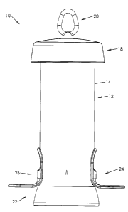
is provided a bird feeder generally designated by reference numeral 10. Bird
feeder 10 is of
the so-called "tube type" and includes a tubular body 12 having a side wall
14. Side wall 14
has an upper marginal edge generally designated by reference numeral 15 and a
lower
marginal edge generally designated by reference numeral 17.
Extending about upper marginal edge 15 is a top ring generally designated by
reference numeral 16. A cover is generally designated by reference numeral 18
while a bail
or hanger is designated by reference numeral 20. Bird feeder 10 also includes
a base
member generally designated by reference numeral 22. A first perch 24 is
mounted on one
side of side wall 14 while a second perch 26 is mounted so as to be
diametrically opposed to
first perch 24.
Side wall 14 has, proximate to lower marginal edge 17, a first side aperture
30 and a
- 5 -
CA 02848952 2014-04-10
second side aperture 32.
Side wall 14 also has a pair of feed access openings 34, 35. Since both are
substantially identical, only one will be described herein. Thus, first feed
access opening 34
is demarcated by a circular line 36 into which there is formed an upper cutout
or recess 38
and a lower cutout or recess 40. Proximate upper marginal edge 15, there are
provided a
plurality of small apertures 41.
Each of perches 24, 26 are substantially identical and thus, only one will be
described
in detail herein. Perch 24 has an overall L-shaped frame; the bottom of the L-
shaped frame
is a U-shaped portion generally designated by reference numeral 46. U-shaped
portion
includes a first leg 48, a second leg 50, and a joinder section 52.
The upper portion of L-shaped frame 44 is also somewhat U-shaped and includes
a
first side leg 54 and a second side leg 56. At the bottom there is a solid
central portion 60.
It will be noted that there is provided a reinforced section 62 from which
extends a
baffle 64. A first lug or projection 66 is located adjacent reinforced section
62 and
baffle 64. Similarly, there is a second lug 68 on the diametrically opposite
side thereof. A
locking lug 70 is provided at the top of joinder section 58 for reasons which
will become
apparent hereinbelow.
For assembly purposes, the perch 24 is inserted when oriented sideways such
that
lugs or projections 66, 68 may pass through recesses 38 and 40. The perch is
then rotated
through 90 to assume the position shown in Figure 22. In this position,
locking lug 70 fits
within recess 38 to lock the perch 24 in position.
Top ring 16 has a side wall 74 which extends downwardly over a portion of side
wall 14 adjacent upper marginal edge 15. A plurality of projections 76 project
inwardly
- 6 -
CA 02848952 2014-04-10
- from side wall 74 and are designed to engage top apertures 41 in side
wall 14 of tubular
body 12. Top ring 16 also includes an upper flange 78 which has a downwardly
extending
sloping surface 80 which functions as a funnel to help ensure that seeds go
inwardly of the
tubular body 12 and at the same time, acts as a stop for placement of the ring
on the seed
tube.
A plurality of cutouts or openings 82 are formed in the outer edge of upper
flange 78
for reasons which will be discussed hereinbelow. Adjacent each cutout or
opening 82 is a
recess 86 formed within flange lower surface 84. Pressure bumps 95 ensure that
the cover is
held in position.
Cover 18 has a top wall 90 and a downwardly extending side wall 92. Formed on
an
interior surface of downwardly extending side wall 92 are three lugs or
projections 94.
These lugs or projections 94 are designed to fit through recess or cutouts 82,
pass over
locking bumps 95 and engage within recesses 86 when the cover is rotated to
thereby latch
the cover in position.
A locking cone is generally designated by reference numeral 96. A plurality of
slots 98 are formed in cone 96 to provide flexibility thereto by forming a
plurality of
segments 99.
A hanger or bail 102 includes a hook portion 104. Hook portion 104 has a
downwardly extending leg 108 with an enlarged end portion 110. The arrangement
is such
that leg 108 may be inserted in an aperture 106 formed in top wall 90.
Enlarged portion 110
will pass through and lock with locking cone 96. Thus, the hanger 102 is
locked in position
while still being capable of rotating.
Base 22 includes an upper base portion generally designated by reference
- 7 -
CA 02848952 2014-04-10
numeral 112. Upper base portion 112 includes a downwardly extending inner side
wall 114
having a hexagonal configuration. An outer side wall 116 surrounds inner side
wall 114 and
outer side wall 116 includes a pair of tabs 118 each having an outwardly
extending flange or
projection 120 at the bottom thereof.
Upper base portion 112 has a pair of half sloping walls 122, 124 forming the
upper
surface thereof and each having respective drainage and ventilation apertures
126, 128
formed therein.
A lower base portion 129 has an outer cylindrical wall 130 and an inner side
wall 132. At the base of inner side wall 132 there is provided an inwardly
extending
flange 134.
Interiorly of inner side wall 132 is a central hexagonal structure 136 which
is
designed to fit within the hexagonally shaped inner side wall 114. The
hexagonal
configuration prevents relative rotation of the lower base portion 129 and the
upper base
portion 112. The interior of hexagonal shaped inner side wall is circular in
configuration
and is designed to receive a post. Interiorly of inner wall 137 is an inner
post 139 which is
arranged to center a post upon which the bird feeder may be mounted. Thus, as
shown in
Figures 17 to 21, several possibilities are provided for. A post 141 may
either have a
swaged end 145 inserted therein or the wider end as desired. Thus, as shown in
Figure 19, a
swaged end 145 is inserted and is supported by inner post 139. In a different
arrangement,
as shown in Figure 20, post 141 is designed to fit within and be supported by
inner wall 137.
Mounted on inner side wall 132 are a pair of projections 138. Each projection
is
substantially identical and thus only one will be described herein. Projection
138 has a
tapering face or front wall 140. Tapering face 140 tapers outwardly as it
extends
- 8 -
CA 02848952 2014-04-10
downwardly and also has a slight taper to either side. This taper permits the
insertion of side
wall 14 of tubular body 12 due to the flexibility of side wall 14. After
insertion and abutting
a stopper, the tubular body may be rotated such that projections 138 will
engage within
apertures 30, 32. The tubular body 12 is then locked into position.
Lower base portion 129 also includes walls 144 which are designed to receive
tabs 118 and be locked into position through projections 120 engaging the
bottom of
walls 144.
In one embodiment of the inventioa, there is provided a seed tray 148. Seed
tray 148
has a bottom sloping wall 150. Bottom sloping wall 150 has an inner portion
156 and an
outer side wall 152. Drainage apertures 154 are provided at the low point of
sloping bottom
wall 150 which is adjacent outer side wall 152.
Exteriorly of outer side wall 152 there is provided a ring 158 which functions
as a
perch. Connecting portions 160 are provided as may be seen in the drawings.
Seed tray 148 has a central aperture which is designed to fit over tubular
body 12.
Seed tray 148 is retained between the bottom of perches 24, 26 and the upper
portion of
base 22.
As will be seen from the above, bird feeder 10 may be assembled and
disassembled
without the use of any tools. Top ring 16 reinforces the upper portion of the
tubular body 10
permitting the use of thinner (and more flexible) material.
As may be seen in Figure 33, cover 18 may be used as a scoop for dipping into
the
bird feed and pouring the same into the seed tube. The tube bird feeder, due
to its structure,
has ventilation and drainage apertures both at the top and bottom to allow for
the exit of hot
air.
- 9 -
CA 02848952 2014-04-10
It will be understood that the above described embodiment is for purposes of
illustration only and that changes and modifications may be made thereto
without departing
from the spirit and scope of the invention.
-10-