Language selection

Search

Patent 2849041 Summary

Third-party information liability

Some of the information on this Web page has been provided by external sources. The Government of Canada is not responsible for the accuracy, reliability or currency of the information supplied by external sources. Users wishing to rely upon this information should consult directly with the source of the information. Content provided by external sources is not subject to official languages, privacy and accessibility requirements.

Claims and Abstract availability

Any discrepancies in the text and image of the Claims and Abstract are due to differing posting times. Text of the Claims and Abstract are posted:

  • At the time the application is open to public inspection;
  • At the time of issue of the patent (grant).
(12) Patent: (11) CA 2849041
(54) English Title: BRAKE CALIPER OF A DISK BRAKE FOR A UTILITY VEHICLE
(54) French Title: ETRIER DE FREIN D'UN FREIN A DISQUE DESTINE A UN VEHICULE UTILITAIRE
Status: Granted
Bibliographic Data
(51) International Patent Classification (IPC):
  • F16D 55/2255 (2006.01)
  • F16D 65/00 (2006.01)
(72) Inventors :
  • GRUBER, MARKUS (Germany)
  • PRITZ, WOLFGANG (Germany)
  • MACK, MARTIN (Germany)
(73) Owners :
  • KNORR-BREMSE SYSTEME FUR NUTZFAHRZEUGE GMBH (Germany)
(71) Applicants :
  • KNORR-BREMSE SYSTEME FUR NUTZFAHRZEUGE GMBH (Germany)
(74) Agent: SMART & BIGGAR LP
(74) Associate agent:
(45) Issued: 2019-03-26
(86) PCT Filing Date: 2012-09-20
(87) Open to Public Inspection: 2013-03-28
Examination requested: 2017-05-11
Availability of licence: N/A
(25) Language of filing: English

Patent Cooperation Treaty (PCT): Yes
(86) PCT Filing Number: PCT/EP2012/068542
(87) International Publication Number: WO2013/041624
(85) National Entry: 2014-03-18

(30) Application Priority Data:
Application No. Country/Territory Date
10 2011 114 107.7 Germany 2011-09-22

Abstracts

English Abstract


The invention relates to a brake caliper of a disk
brake for a utility vehicle, comprising two tension
braces, which are arranged substantially parallel and
at a distance from each other, bridge a brake disk
perpendicularly to the rotational direction of the
brake disk in the assembled position, and connect
receptacles for functional parts arranged on both sides
of the brake disk to one another, wherein one
receptacle forms a caliper back and the other
receptacle forms a housing having a lever dome formed
thereon. The brake caliper is designed in such a way
that respective replaceable protective elements are
fastened at each potential area of wear caused by
operation.


French Abstract

L'invention concerne un étrier de frein (1) d'un frein à disque destiné à un véhicule utilitaire, lequel comporte deux entretoises de traction (4) lesquelles sont disposées sensiblement en parallèle et à l'écart l'une de l'autre, lesquelles sont montées tel qu'elles s'étendent à travers un disque de frein dans un sens perpendiculaire au sens de rotation de ce dernier, lesquelles relient des logements pour pièces fonctionnelles disposés des deux côtés dudit disque de frein, l'un desdits logements formant un dos d'étrier (3) et l'autre formant un boîtier (2) pourvu d'une excroissance à effet levier (5) y étant rapportée, et lequel est réalisé tel qu'un élément de protection (8, 13) échangeable est fixé sur chacune des zones susceptibles de subir une usure lors du fonctionnement.

Claims

Note: Claims are shown in the official language in which they were submitted.

8

Claims
1. A brake caliper of a disk brake for a utility vehicle, having
two tension braces, which are arranged substantially parallel
and at a distance from one another, bridge a brake disk
transversely to the direction of rotation thereof in an
assembled position, and connect receptacles for functional
parts arranged on both sides of the brake disk to one another,
wherein a first receptacle forms a caliper back and a second
receptacle forms a housing having a lever dome formed thereon;
and at least one replaceable protective element located at at
least one area of service-related wear on the break caliper,
wherein the at least one replaceable protective element
comprises a tension brace protector arranged on an underside
of the tension brace facing away from the lever dome, or a
lever dome protector, or both.
2. The brake caliper as claimed in claim 1, wherein one of the at
least one replaceable protective element is the tension brace
protector.
3. The brake caliper as claimed in claim 1 or 2, wherein the
tension brace protector is secured on the tension brace
situated at the leading edge in relation to the brake disk.
4. The brake caliper as claimed in any one of claims 1-3, wherein
the tension brace protector projects outward beyond the
tension brace.
5. The brake caliper as claimed in any one of claims 1-4, wherein
the tension brace protector is of stirrup-shaped design,
having a bar and two angled lugs, in which holes for the
passage of fastening screws are provided.

9

6. The brake caliper as claimed in claim 5, wherein the bar
projects outward in relation to the tension brace.
7. The brake caliper as claimed in any one of claims 1-6, wherein
one of the at least one replaceable protective element is the
lever dome protector.
8. The brake caliper as claimed in claim 7, wherein the lever
dome protector is of horseshoe configuration and has two
angled lugs having through holes for passing through fastening
screws.
9. The brake caliper as claimed in claim 7 or 8, wherein the
lever dome protector is connected to a flange of the lever
dome.
10. The brake caliper as claimed in any one of claims 7-9, wherein
the lever dome protector rests on the housing and partially
surrounds the lever dome.
11. The brake caliper as claimed in any one of claims 7-10,
wherein the lever dome protector has a height equal to or
greater than the height of the lever dome.

Description

Note: Descriptions are shown in the official language in which they were submitted.


1
Brake caliper of a disk brake for a utility vehicle
The invention relates to a brake caliper of a disk brake for a
utility vehicle.
The brake caliper, as part of a disk brake, serves essentially to
receive functional parts required for the operation of the disk
brake. These include, for example, an application device, which is
arranged in a receiving chamber of the brake caliper, and brake
pads, which are positioned on both sides of a brake disk and which
are pressed against the brake disk during braking.
The two brake caliper halves which receive the functional parts,
one of which forms a housing and other forms a caliper back, are
connected to one another by tension braces, which furthermore
absorb mechanical loads that occur during braking.
The application device mentioned includes a brake lever, which is
covered over in relation to the external environment by a lever
dome formed on the housing.
In addition to receiving the functional parts, the brake caliper
also serves to protect them from the effects of weather and from
dirt, especially since the brake disk is installed in an
unprotected region of a vehicle rim, which is heavily exposed to
dirt.
However, the brake caliper itself is subject to abrasive wear,
particularly in certain areas, owing to its exposed position,
leading ultimately to a reduction in the service life of the disk
brake overall, especially since the brake caliper is designed as a
casting and therefore the worn areas cannot be replaced.
CA 2849041 2018-10-10

2
Of course, this drawback is not acceptable, particularly from an
economic point of view, especially since cast-iron brake calipers
are designed for a significantly longer life than they actually
achieve in practice due to the loading mentioned.
Moreover, said abrasive wear on the brake caliper can lead to a
creeping reduction in the operational reliability of the disk brake
since the tension braces, for example, are exposed to a
considerable tensile loading, for which they are appropriately
dimensioned.
In the case of wear-induced weakening of the tension braces,
therefore, fracture may occur, making the entire disk brake
incapable of functioning, with the resulting consequences, which do
not need to be detailed.
It is the underlying object of the invention to develop a brake
caliper of the type in question in such a way that its service life
is optimized and the operational reliability of the disk brake
overall is improved.
This object is achieved by a brake caliper having the features
described herein.
In one aspect, there is provided a brake caliper of a disk brake
for a utility vehicle, having two tension braces, which are
arranged substantially parallel and at a distance from one another,
bridge a brake disk transversely to the direction of rotation
thereof in an assembled position, and connect receptacles for
functional parts arranged on both sides of the brake disk to one
another, wherein a first receptacle forms a caliper back and a
second receptacle forms a housing having a lever dome formed
thereon; and at least one replaceable protective element located at
CA 2849041 2018-10-10

2a
at least one area of service-related wear on the break caliper,
wherein the at least one replaceable protective element comprises a
tension brace protector arranged on an underside of the tension
brace facing away from the lever dome, or a lever dome protector,
or both.
With very low outlay in terms of design and manufacture, the
invention provides a brake caliper, the service life of which is no
longer determined by factors extraneous to the system.
Although there is abrasive wear on the brake caliper, as before, it
is only on the protective elements fitted, the positioning of which
is known from practical experience.
Thus, in practice, it has been found that the areas of service-
related wear, namely of abrasive wear, are found particularly on
the tension brace which is on the
CA 2849041 2018-10-10

CA 02849041 2014-03-18
3
leading edge, in relation to the rotating brake disk,
and on the lever dome.
Corresponding protective elements are now provided
here, and these are preferably designed as formed sheet
metal parts and can be produced in a particularly
simple manner by punching.
As a result, these protective elements can be provided
at extraordinarily low cost, all that is required for
fastening them being fastening means. Particularly
suitable for this purpose are screws, which are screwed
into prepared threaded holes in the tension brace and
the lever dome.
In the case of a pneumatically actuated disk brake, a
flange, on which a brake cylinder can be secured, is
formed on the rear of the lever dome. This flange can
also be used to fix the protective element, using the
screws by means of which the brake cylinder is
connected to the flange.
According to another concept of the invention, it is
envisaged that protective elements on the tension brace
should be designed in the manner of a plate-shaped
stirrup with laterally formed fastening lugs, wherein
this tension brace protector projects laterally outward
over virtually the entire length of the tension brace.
The protective element for the lever dome, referred to
as a lever dome protector, is preferably of horseshoe
configuration and forms a stripper, e.g. for ice
adhering to the rim, which would otherwise be stripped
off by the lever dome, as is the case in the prior art.
In order to obtain protective elements with as long a
life as possible, these are composed of a wear-
resistant material, in particular an appropriate metal,
wherein, as mentioned, these protective elements can be

4
replaced when required at any time without major effort, thus
ensuring that the brake caliper achieves the desired service life
without problems, or at least without service-related external
influences on the potential areas of wear.
Further advantageous embodiments of the invention are characterized
herein.
An illustrative embodiment of the invention is described below by
means of the attached drawings, in which:
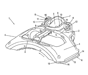
Figure 1 shows a brake caliper according to the invention in a
perspective plan view
Figure 2 shows a perspective bottom view of the brake caliper.
In the figures, a caliper 1 of a disk brake for a utility vehicle
is shown, said caliper being composed substantially of cast iron
and having two tension braces 4, which are arranged parallel and at
a distance from one another, bridge a brake disk transversely to
the direction of rotation thereof in the assembled position, and
connect receptacles for functional parts arranged on both sides of
the brake disk to one another, wherein one receptacle forms a
caliper back 3 and the other receptacle forms a housing 2 having a
lever dome 5 formed thereon.
According to the invention, a replaceable protective element is
fastened at each potential area of service-related wear.
In the example shown, one protective element is secured as a
tension brace protector 6 on the underside of the tension brace 4
situated at the leading edge in relation to the direction of
rotation of the brake disk
CA 2849041 2018-10-10

CA 02849041 2014-03-18
(not shown) in normal operation, wherein the direction
of rotation is indicated by an arrow in figure 1.
As figure 2, in particular, very clearly shows, the
tension brace protector 6 is of stirrup-shaped design,
having a bar 13 and angled connection lugs 14, 15 at
the ends, which each have a hole 17 for the passage of
a screw, preferably a cap screw, which can be screwed
into a nut thread (not shown) of the tension brace 4,
allowing the tension brace protector 6 to be replaced
without problems.
In the transition zone to the bar 13, that connection
lug 15 of the tension brace protector 6 which is remote
from the housing 2 has a bevel 16 to match the contour
of the tension brace 4 in this region.
Figure 1 shows very clearly that the bar 13 projects
outward beyond the tension brace 4, providing effective
protection for the tension brace 4 from dirt thrown up
by a rim.
The lever dome 5, likewise recognized as a potential
area of service-related wear, is likewise protected by
a protective element, formed by a lever dome protector
8. This is of horseshoe configuration and, on the one
hand, is supported on the housing region adjacent to
the lever dome 5 and, on the other hand, is secured on
a flange 7, to which a brake cylinder is connected in
operation.
The lever dome protector 8, with two legs 9 extending
approximately parallel to one another and a convexly
curved web 9 connecting them, has lugs 11 angled
outward at the free ends of the legs 10, with through
holes 12 for the passage of fastening screws.
The height of the lever dome protector 8 is dimensioned
in such a way that it projects above the lever dome 5

CA 02849041 2014-03-18
6
at least slightly, and effective protection of the
lever dome 5 is achieved as a result.
In principle, of course, there is the possibility also
of attaching protective elements to regions of the
brake caliper 1 other than those shown if practical
experience shows that this is necessary.

CA 02849041 2014-03-18
7
List of reference signs
1 brake caliper
2 housing
3 caliper back
4 tension brace
lever dome
6 tension brace protector
7 flange
8 lever dome protector
9 web
leg
11 lug
12 hole
13 bar
14 connection lug
connection lug
16 bevel
17 hole

Representative Drawing
A single figure which represents the drawing illustrating the invention.
Administrative Status

For a clearer understanding of the status of the application/patent presented on this page, the site Disclaimer , as well as the definitions for Patent , Administrative Status , Maintenance Fee  and Payment History  should be consulted.

Administrative Status

Title Date
Forecasted Issue Date 2019-03-26
(86) PCT Filing Date 2012-09-20
(87) PCT Publication Date 2013-03-28
(85) National Entry 2014-03-18
Examination Requested 2017-05-11
(45) Issued 2019-03-26

Abandonment History

There is no abandonment history.

Maintenance Fee

Last Payment of $263.14 was received on 2023-09-06


 Upcoming maintenance fee amounts

Description Date Amount
Next Payment if standard fee 2024-09-20 $347.00
Next Payment if small entity fee 2024-09-20 $125.00

Note : If the full payment has not been received on or before the date indicated, a further fee may be required which may be one of the following

  • the reinstatement fee;
  • the late payment fee; or
  • additional fee to reverse deemed expiry.

Patent fees are adjusted on the 1st of January every year. The amounts above are the current amounts if received by December 31 of the current year.
Please refer to the CIPO Patent Fees web page to see all current fee amounts.

Payment History

Fee Type Anniversary Year Due Date Amount Paid Paid Date
Application Fee $400.00 2014-03-18
Maintenance Fee - Application - New Act 2 2014-09-22 $100.00 2014-09-11
Maintenance Fee - Application - New Act 3 2015-09-21 $100.00 2015-09-04
Maintenance Fee - Application - New Act 4 2016-09-20 $100.00 2016-09-14
Request for Examination $800.00 2017-05-11
Maintenance Fee - Application - New Act 5 2017-09-20 $200.00 2017-09-06
Maintenance Fee - Application - New Act 6 2018-09-20 $200.00 2018-09-05
Final Fee $300.00 2019-02-06
Maintenance Fee - Patent - New Act 7 2019-09-20 $200.00 2019-09-09
Maintenance Fee - Patent - New Act 8 2020-09-21 $200.00 2020-09-10
Maintenance Fee - Patent - New Act 9 2021-09-20 $204.00 2021-09-13
Maintenance Fee - Patent - New Act 10 2022-09-20 $254.49 2022-09-06
Maintenance Fee - Patent - New Act 11 2023-09-20 $263.14 2023-09-06
Owners on Record

Note: Records showing the ownership history in alphabetical order.

Current Owners on Record
KNORR-BREMSE SYSTEME FUR NUTZFAHRZEUGE GMBH
Past Owners on Record
None
Past Owners that do not appear in the "Owners on Record" listing will appear in other documentation within the application.
Documents

To view selected files, please enter reCAPTCHA code :


To view images, click a link in the Document Description column. To download the documents, select one or more checkboxes in the first column and then click the "Download Selected in PDF format (Zip Archive)" or the "Download Selected as Single PDF" button.

List of published and non-published patent-specific documents on the CPD .

If you have any difficulty accessing content, you can call the Client Service Centre at 1-866-997-1936 or send them an e-mail at CIPO Client Service Centre.


Document
Description 
Date
(yyyy-mm-dd) 
Number of pages   Size of Image (KB) 
Abstract 2014-03-18 1 17
Claims 2014-03-18 2 60
Drawings 2014-03-18 2 70
Description 2014-03-18 7 196
Representative Drawing 2014-03-18 1 77
Cover Page 2014-05-02 1 69
Request for Examination 2017-05-11 2 65
Examiner Requisition 2018-05-08 3 202
Amendment 2018-10-10 10 326
Description 2018-10-10 8 223
Claims 2018-10-10 2 56
Drawings 2018-10-10 2 55
Abstract 2019-01-21 1 18
Final Fee 2019-02-06 2 60
Representative Drawing 2019-02-27 1 21
Cover Page 2019-02-27 1 53
PCT 2014-03-18 12 373
Assignment 2014-03-18 2 66
Correspondence 2015-11-13 4 109