Note: Descriptions are shown in the official language in which they were submitted.
-1-
BEARING ASSEMBLIES, APPARATUSES, AND RELATED METHODS OF
MANUFACTURE
BACKGROUND
[0002] Subterranean drilling systems that employ downhole drilling
motors are
commonly used for drilling boreholes in the earth for oil and gas exploration.
Subterranean drilling systems typically include a housing enclosing a downhole
drilling
motor operably connected to an output shaft. One or more thrust-bearing
apparatuses
may also be operably coupled to the downhole drilling motor for carrying
thrust loads
generated during drilling operations. A rotary drill bit may also be connected
to the
output shaft and be configured to engage a subterranean formation and drill a
borehole.
As the borehole is drilled with the rotary drill bit, pipe sections may be
connected to the
subterranean drilling system to form a drill string capable of progressively
drilling the
borehole to a greater size or depth within the earth.
[0003] Each bearing apparatus may include a stator that does not
rotate and a rotor
that is attached to the output shaft and rotates with the output shaft The
stator and rotor
may each include a plurality of superhard bearing elements or inserts. Each
superhard
bearing element may be fabricated from a polycrystalline diamond compact
("PDC") that
provides a bearing surface that bears against other bearing surfaces during
use.
[0004] In a conventional PDC bearing apparatus, a bearing assembly may
include a
support ring that includes recesses configured to accept the superhard bearing
elements.
The superhard bearing elements may be partially disposed in the recesses of
the support
ring and secured partially therein via brazing or other processes. However,
heating and/or
cooling from brazing and other processes may generate significant residual
stresses in the
superhard bearing elements. These residual stresses alone and/or in
combination with
operational loads may cause fracturing and/or weakening of the superhard
bearing
elements which may result in failure of bearing assemblies and/or bearing
apparatuses.
[0005] Therefore, manufacturers and users of bearing apparatuses continue
to seek
improved bearing assembly and apparatus designs and manufacturing techniques.
CA 2849165 2019-01-11
CA 02849165 2014-03-18
WO 2013/043917
PCT/US2012/056407
-2-
SUMMARY
[0006] Various embodiments of the invention relate to bearing assemblies
and
apparatuses that may include a support ring to which one or more superhard
bearing
elements may be secured. The support ring may include one or more relief
features
configured to reduce residual stresses formed in the superhard bearing
elements by
brazing the superhard bearing elements to the support ring, operational loads,
or other
processes. The various embodiments of the bearing assemblies and apparatuses
may be
used in subterranean drilling systems and/or other types of systems.
[0007] In an embodiment, a bearing assembly for use in a subterranean
drilling
system may include a plurality of superhard bearing elements and a support
ring. The
support ring may include a plurality of recesses distributed circumferentially
about a
rotation axis. A corresponding one of the plurality of superhard bearing
elements may be
affixed to the support ring in a corresponding one of the plurality of
recesses. The
bearing assembly may also include a plurality of relief features formed in the
support
ring. Each of the plurality of relief features may be disposed between
adjacent recesses of
the plurality of recesses. In an embodiment, the plurality of relief features
may be
configured to reduce residual stresses in the plurality of superhard bearing
elements
caused by securing (e.g., brazing) the plurality of superhard bearing elements
to the
support ring.
[0008] In an embodiment, a bearing apparatus for use in a subterranean
drilling
system may include a first bearing assembly and a second bearing assembly. The
first
bearing assembly may include a plurality of first superhard bearing elements
each of
which may include a first bearing surface. The first bearing assembly may also
include a
support ring that may include a plurality of recesses distributed
circumferentially about a
rotation axis. A corresponding one of the plurality of first superhard bearing
elements
may be affixed to the support ring in a corresponding one of the plurality of
recesses. The
support ring may also include a plurality of relief features formed in the
support ring.
Each of the plurality of relief features may be disposed between adjacent
recesses of the
plurality of recesses. The second bearing assembly may include a plurality of
second
superhard bearing elements each of which may include a second bearing surface
generally
opposing the first bearing surfaces of the plurality of first superhard
bearing elements. In
an embodiment, the plurality of relief features may be configured to reduce
residual
stresses in the plurality of first superhard bearing elements caused by
securing (e.g.,
brazing) the plurality of first superhard bearing elements to the support
ring.
CA 02849165 2014-03-18
WO 2013/043917
PCT/US2012/056407
-3-
[0009] In an embodiment, a method for manufacturing a bearing assembly for
use in a
subterranean drilling system may include providing a support ring. The support
ring may
include a plurality of recesses distributed circumferentially about an axis.
The support
ring may also include a plurality of relief features formed in the support
ring, and each of
the relief features may be disposed between adjacent recesses of the plurality
of recesses.
The plurality of superhard bearing elements may be brazed to the support ring
without
forming cracks in at least a portion of the plurality of superhard bearing
elements that
extend generally perpendicular to the axis.
[0010] Other embodiments include applications utilizing the disclosed
bearing
assemblies in various types of drilling systems and other applications.
[0011] Features from any of the disclosed embodiments may be used in
combination
with one another, without limitation. In addition, other features and
advantages of the
present disclosure will become apparent to those of ordinary skill in the art
through
consideration of the following detailed description and the accompanying
drawings.
BRIEF DESCRIPTION OF THE DRAWINGS
[0012] The drawings illustrate several embodiments of the invention,
wherein
identical reference numerals refer to identical elements or features in
different views or
embodiments shown in the drawings.
[0013] FIG. 1A is an isometric view of a radial bearing assembly
according to an
embodiment;
[0014] FIG. 1B is an isometric view of the radial bearing assembly shown in
FIG.
lA with the superhard bearing elements removed;
[0015] FIG. 1C is a cross-sectional view of the support ring shown in
FIG. 1B;
[0016] FIGS. 2A-2C are partial isometric views of radial bearing
assemblies
according to other embodiments;
100171 FIG. 3 is an isometric cutaway view of a radial bearing apparatus
according to
an embodiment;
[0018] FIG. 4 is an isometric view of a thrust-bearing assembly according
to an
embodiment;
[0019] FIG. 5 is an isometric cutaway view of a thrust-bearing apparatus
that may
utilize any of the disclosed thrust-bearing assemblies according to an
embodiment;
[0020] FIG. 6A is an isometric cutaway view of an angular contact bearing
apparatus
according to an embodiment;
CA 02849165 2014-03-18
WO 2013/043917
PCT/US2012/056407
-4-
[0021] FIG. 6B is a partial cross-sectional view taken along line 6B-6B of
the angular
contact bearing apparatus shown in FIG. 6A; and
[0022] FIG. 7 is a schematic isometric cutaway view of a subterranean
drilling
system including a thrust-bearing apparatus utilizing any of the described
bearing
assemblies according to various embodiments.
DETAILED DESCRIPTION
[0023] Embodiments of the invention relate to bearing assemblies, bearing
apparatuses, and motor assemblies that include support rings having relief
features
configured to prolong the useful life of superhard bearing elements secured to
the support
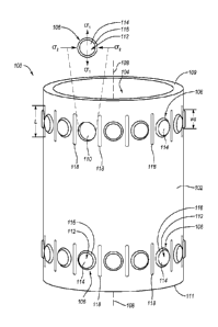
rings. FIG. lA is an isometric view of a radial bearing assembly 100 according
to an
embodiment. The radial bearing assembly 100 may form a stator or a rotor of a
radial
bearing apparatus used in a subterranean drilling system, a pump, a turbine,
and/or other
types of systems. The radial bearing assembly 100 may include a support ring
102
defining an opening 104 through which a shaft or spindle (not shown) of, for
example, a
drilling motor may extend. The support ring 102 may be made from a variety of
different
materials. For example, the support ring 102 may comprise carbon steel,
stainless steel,
tungsten carbide, or another suitable material.
[0024] The radial bearing assembly 100 further may include a plurality of
superhard
bearing elements 106. The plurality of superhard bearing elements 106 may be
distributed about a rotation axis 108 in corresponding recesses 110 (see FIG.
1B) formed
in the support ring 102 and arranged in a first row and a second row. In other
embodiments, the superhard bearing elements 106 may be circumferentially
distributed
about the axis 108 in a single row, three rows, or any number of rows. The
superhard
bearing elements 106 may be generally cylindrical, generally non-cylindrical,
generally
rectangular, generally wedge shaped, or any other suitable configuration.
100251 Some or all of the superhard bearing elements 106 may comprise a
superhard
table 112 including a convexly-curved bearing surface 114 (e.g., curved to lie
on an
imaginary cylindrical surface). In other embodiments, the bearing surfaces 114
may be
concavely-curved or have other suitable shapes. Each superhard table 112 may
be
bonded or attached to a corresponding substrate 116. A portion of or all of
the superhard
.. bearing elements 106 may be partially secured in the recesses 110 via
brazing, welding,
soldering, press-fitting, fastening with a fastener, or another suitable
technique. As used
herein a "superhard bearing element" is a bearing element including a bearing
surface that
is made from a material exhibiting a hardness that is at least as hard as
tungsten carbide.
-5-
[0026] In any of the embodiments disclosed herein, the superhard bearing
elements
106 may be made from one or more superhard materials, such as polycrystalline
diamond,
polycrystalline cubic boron nitride, silicon carbide, tungsten carbide, or any
combination
of the foregoing superhard materials. For example, the superhard table may be
formed
from polycrystalline diamond and the substrate may be formed from cobalt-
cemented
tungsten carbide. Furthermore, in any of the embodiments disclosed herein, the
polycrystalline diamond table may be leached to at least partially or
substantially
completely remove a metal-solvent catalyst (e.g., cobalt, iron, nickel, or
alloys thereof)
that was used to initially sinter precursor diamond particles that form the
polycrystalline
diamond. In another embodiment, an infiltrant used to re-infiltrate a
preformed leached
polycrystalline diamond table may be leached or otherwise removed to a
selected depth
from a bearing surface. Moreover, in any of the embodiments disclosed herein,
the
polycrystalline diamond may be unleached and include a metal-solvent catalyst
(e.g.,
cobalt, iron, nickel, or alloys thereof) that was used to initially sinter the
precursor
diamond particles that form the polycrystalline diamond or an infiltrant used
to re-
infiltrate a preformed leached polycrystalline diamond table. Other examples
of methods
for fabricating the superhard bearing elements are disclosed in U.S, Patent
Nos.
7,866,418, 7,842,111; and co-pending U.S. Patent Application No. 11/545,929.
[0027] The diamond particles that may form the polycrystalline diamond
in the
superhard table 112 may also exhibit a larger size and at least one relatively
smaller size.
As used herein, the phrases "relatively larger" and "relatively smaller" refer
to particle
sizes (by any suitable method) that differ by at least a factor of two (e.g.,
30 gm and 15
gm). According to various embodiments, the diamond particles may include a
portion
exhibiting a relatively larger size (e.g., 30 pun, 20 um, 15 pan, 12 pun, 10
pun, 8 um) and
another portion exhibiting at least one relatively smaller size (e.g., 6 gm, 5
gni, 4 gin, 3
urn, 2 gm, 1 gm, 0.5 gm, less than 0.5 gm, 0.1 gm, less than 0.1 gm). In an
embodiment,
the diamond particles may include a portion exhibiting a relatively larger
size between
about 10 gm and about 40 gm and another portion exhibiting a relatively
smaller size
between about 1 gm and 4 gm. In some embodiments, the diamond particles may
comprise three or more different sizes (e.g., one relatively larger size and
two or more
relatively smaller sizes), without limitation.
[0028] Additionally, in any of the embodiments disclosed herein, the
superhard
bearing elements 106 may be free-standing (e.g., substrateless) and formed
from a
CA 2849165 2019-01-11
CA 02849165 2014-03-18
WO 2013/043917
PCT/US2012/056407
-6-
polycrystalline diamond body that is at least partially or fully leached to
remove a metal-
solvent catalyst initially used to sinter the polycrystalline diamond body.
[0029] In the illustrated embodiment, the support ring 102 may include
relief features
(e.g., stress-relief features) configured to reduce residual stresses
including compressive
hoop stresses, tensile axial stresses, combinations thereof, and the like that
may be
induced in the superhard bearing elements 106 by securing the superhard
bearing
elements 106 to the support ring 102 by brazing or other method, operational
loads, other
processes, or combinations of the foregoing. For example, the superhard
bearing
elements 106 may be secured to the support ring 102 via a thermal process such
as
brazing. Brazing may cause the recesses 110 of the support ring 102 to expand
and
contract relative to the superhard bearing elements 106 because the support
ring 102
generally has a coefficient of thermal expansion greater than that of the
superhard bearing
elements 106. When the recesses 110 contract, the recesses 110 of the support
ring 102
may place compressive hoop stresses G2 on the superhard bearing elements 106.
These
compressive hoop stresses G2 may generate residual stresses in the superhard
bearing
elements 106 that can give rise to damage (e.g., tensile fracture) on the
superhard bearing
elements 106. More specifically, as shown in FIG. 1A, residual compressive
hoop
stresses al may induce axial tensile stresses Gi in the superhard bearing
elements 106 that
may damage the superhard bearing elements 106. Operational loads (not shown)
may
also add to the residual stresses within the superhard bearing elements 106
and cause
failure that would otherwise not have occurred.
[0030] In an embodiment, one or more grooves 118 may be formed in the
support
ring 102 between adjacent (e.g., immediately adjacent) ones of the superhard
bearing
elements 106 and the recesses 110. The grooves 118 may be configured to help
reduce
the residual stresses in the superhard bearing elements 106 as a result of
brazing the
superhard bearing elements 106 to the support ring 102, operational loads,
other
processes, or combinations thereof. The grooves 118 may be configured to
reduce the
residual stresses in the superhard bearing elements 106 by functioning to at
least partially
segment the support ring 102 between the recesses 110 to lessen the clamping
pressure on
the superhard bearing elements 106 by making the support ring 102 more
compliant (i.e.,
less stiff) in a circumferential direction. In other embodiments, the grooves
118 may be
configured to reduce brazing-induced stresses in the superhard bearing
elements 106 by
functioning as expansion/contraction joints between the recesses 110 to
compensate for
thermal expansion and/or contraction of the recesses 110 relative to the
superhard bearing
CA 02849165 2014-03-18
WO 2013/043917
PCT/US2012/056407
-7-
elements 106. In yet other embodiments, the grooves 118 may be configured to
function
as heat dissipaters to attract energy in the form of heat away from the
recesses 110 and
the superhard bearing elements 106. More specifically, the grooves 118 may
provide a
larger heat dissipation surface area between the recesses 110 such that the
temperature
rise of the support ring 102 between the recesses 110 due to brazing, during
use, or other
processes is lower.
[0031] By reducing the residual stresses in the superhard bearing
elements 106, the
grooves 118 may reduce fracturing on the superhard bearing elements 106 and
may
advantageously help prolong the useful life of the superhard bearing elements
106.
[0032] As shown in FIGS. lA and 1B, the grooves 118 may have a generally
semi-
cylindrical shape. While the grooves 118 are illustrated having a generally
semi-
cylindrical shape, the grooves 118 may have a generally rectangular shape, a
generally
crescent shape, a generally diamond shape, combinations thereof, or any other
shape
suitable to help reduce stresses in the superhard bearing elements 106. In the
illustrated
embodiment, the grooves 118 may have substantially the same configuration and
shape.
In other embodiments, the grooves 118 may have configurations and/or shapes
that vary
from one groove 118 to another groove 118. For example, a first one of the
grooves 118
may have a generally diamond shape, a second one of the grooves 118 may have a
generally semi-cylindrical shape, and a third one of the grooves 118 may have
a generally
rectangular shape.
[0033] Each of the grooves 118 may have a maximum length Las shown in FIG.
1A.
The maximum length L of one or more of the grooves 118 may extend between
opposite
end portions of the grooves 118. In an embodiment, the maximum length L of at
least
one of the grooves 118 may be about 0.3 inches to about 1.5 inches, such as
about 0.5
inches to about 0.8 inches. However, in other embodiments, the maximum length
L of at
least one of the grooves 118 may be longer or shorter than the foregoing
ranges for the
maximum length L. As illustrated, each of the grooves 118 may have at least
substantially the same maximum length L. However, in other embodiments, some
or all
of the grooves 118 may have substantially different maximum lengths L. For
example, in
an embodiment, the support ring 102 may include a first group of grooves 118
having
maximum lengths of about 1.2 inches and a second group of grooves 118 having
maximum lengths of about 0.6 inches. In some embodiments, at least some of the
grooves 118 may extend to an upper end surface 109 or a lower end surface 111.
CA 02849165 2014-03-18
WO 2013/043917
PCT/US2012/056407
-8-
[0034] In an embodiment, the relationship between the maximum length L of
at least
one the grooves 118 and a maximum width WR of at least one of the recesses
(shown in
FIG. 1C) may be configured to help reduce the stiffness of the support ring
102 during
brazing and/or use. Increasing the maximum length L of the grooves 118
relative to the
maximum width WR of the recesses 110 may increase the heat exchange surface
between
the grooves 118 and the recesses 110 and/or create greater
expansion/contraction joints in
the grooves 118 for the recesses 110. For example, the maximum length L of at
least one
of the grooves 118 may be at least: about ninety (90) percent; about one
hundred (100)
percent; about one hundred and ten (110) percent; about one hundred and twenty
(120)
percent; about one hundred and thirty (130) percent; about one hundred and
forty (140)
percent; or about one hundred and fifty (150) percent of the maximum width WR
of the
recesses 110. In other embodiments, the maximum length L of the grooves 118
may be
about one hundred (100) percent to about one hundred and forty (140) percent;
about one
hundred and ten (110) percent to about one hundred and thirty (130) percent;
or at least
about one hundred and twenty (120) percent of the maximum width WR of at least
one of
the recesses 110. In other embodiments, the maximum length L of at least one
of the
grooves 118 and the maximum width WR of at least one of the recesses 110 may
be
larger or smaller relative to each other.
[0035] Similar to the relationship between the maximum length L of the
grooves 118
and the maximum width WR of the recesses 110, the relationship between the
maximum
length L of at least one of the grooves 118 and a maximum width WS of at least
one of
the superhard bearing elements 106 (shown in FIG. 1A) may be configured to
help
reduce the residual stresses in the superhard bearing elements 106 that are
brazed into
support ring 102. For example, the maximum length L of at least one of the
grooves 118
may be at least: about ninety (90) percent; about one hundred (100) percent;
about one
hundred and ten (110) percent; about one hundred and twenty (120) percent;
about one
hundred and thirty (130) percent; about one hundred and forty (140) percent;
and/or about
one hundred and fifty (150) percent of the maximum width WS of at least one of
the
superhard bearing elements 106. In other embodiments, the maximum length L of
at least
one of the grooves 118 may be between about one hundred (100) percent and
about one
hundred and forty (140) percent; or between about one hundred and ten (110)
percent and
about one hundred and thirty (130) percent, and/or about one hundred and
twenty (120)
percent of the maximum width WS of at least one of the superhard bearing
elements 106.
In other embodiments, the maximum length L of at least one of the grooves 118
and the
CA 02849165 2014-03-18
WO 2013/043917
PCT/US2012/056407
-9-
maximum width WS of at least one of the superhard bearing elements 106 may be
larger
or smaller relative to each other.
100361 Referring now to FIG. IC, each of the grooves 118 may also include
a
maximum depth D and a maximum width W. Generally, the maximum depth D may
extend only partially through the support ring 102 or completely through the
support ring
102. For example, the maximum depth D may be about 0.1 inches to about 0.4
inches,
such as about 0.15 inches to about 0.25 inches. Variations of the maximum
depth D
and/or the maximum width W of the grooves 118 may help the grooves 118
function as
heat dissipaters, expansion/contraction joints, and/or to segment the support
ring 102 to
help reduce the stiffness and/or displacement of the support ring 102 during
brazing
and/or use.
[0037] As illustrated, the grooves 118 may be formed in a section of a
wall 120 of the
support ring 102. The wall 120 may have a thickness T that extends between an
outer
surface 122 and an inner surface 124. The maximum depth D of the grooves 118
may
extend between the outer surface 122 of the wall 120 and a lower surface
within the
grooves 118, or the grooves 118 may extend completely through the wall 120
(i.e.,
through slots or grooves). As illustrated, the grooves 118 may have at least
substantially
the same maximum depth D. However, in other embodiments, some or all of the
grooves
118 may have substantially different maximum depths D. In addition, the
maximum
depths D of the grooves 118 may vary. For example, at least one of the grooves
118 may
.. have a maximum depth D that includes a deeper portion and a shallower
portion.
[0038] In an embodiment, the relationship between the maximum depth D of
at least
one of the grooves 118 and the thickness T of the wall 120 may be configured
to help
reduce the residual stresses in the superhard bearing elements 106. For
example, the
maximum depth D of at least one of the grooves 118 may be about thirty (30)
percent to
about ninety (90) percent; about forty (40) percent to about eighty (80)
percent; about
fifty (50) percent to seventy (70) percent; about fifty-five (55) percent to
about sixty-five
(65) percent of the thickness T of the wall 120. In another embodiment, the
depth D of at
least one of the grooves 118 may be at least about forty (40) percent, at
least about fifty
(50) percent, at least about sixty (60) percent, about seventy (70) percent,
or at least about
eighty (80) percent of the thickness T of the wall 120. In other embodiments,
the
maximum depth D of the grooves 118 and the thickness T of the wall 120 may be
larger
or smaller relative to each other. For example, in an embodiment, the maximum
depth D
of the grooves 118 may extend entirely through the thickness T of the wall
120.
CA 02849165 2014-03-18
WO 2013/043917
PCT/US2012/056407
-10-
[0039] As shown in FIG. 1C, the maximum width W of each of the grooves may
extend between opposing sidewalls of the grooves 118. In an embodiment, the
maximum
width W of at least one of the grooves 118 may be about 0.1 inches to about
0.3 inches,
such as about 0.125 inches to about 0.2 inches. In other embodiments, the
maximum
widths W of at least one of the grooves 118 may be wider or narrower. As
illustrated, the
grooves 118 may have at least substantially the same maximum widths W.
However, in
other embodiments, some or all of the grooves 118 may have substantially
different
maximum widths W. In addition, the maximum widths W of the grooves 118 may
vary.
For example, at least one of the grooves 118 may have a maximum width W that
includes
a narrower portion and a wider portion.
[0040] In an embodiment, the relationship between the maximum width W of at
least
one of the grooves 118 and the maximum width WR of at least one of the
recesses 110
may be configured to help reduce the stiffness and/or displacement of the
support ring
102 during brazing or use. For example, the maximum width W of at least one of
the
grooves 118 may be at least: about ten (10) percent; about fifteen (15)
percent; about
twenty (20) percent; about twenty-five (25) percent; or about thirty (30)
percent of the
WR of the recesses 110. In addition, the maximum width of grooves 118 may be
about
ten (10) percent to about thirty (30) percent; or about fifteen (15) percent
to about twenty-
five (25) percent; or at least about twenty (20) percent of the maximum width
WR of the
recesses 110. In other embodiments, the maximum widths W of the grooves 118
and the
maximum widths WR of the recesses 110 may be larger or smaller relative to
each other.
[0041] In an embodiment, the relationship between the maximum width W of
at least
one of the grooves 118 and the maximum width WS of at least one of the
superhard
bearing elements 106 may be configured to help reduce the residual stresses
due to
brazing of the superhard bearing elements 106 into the support ring 102. For
example,
the maximum width W of at least one of the grooves 118 may be at least: about
ten (10)
percent; about fifteen (15) percent; about twenty (20) percent; about twenty-
five (25)
percent; or about thirty (30) percent of the maximum width WS of the superhard
bearing
elements 106. In addition, the maximum width W of at least one of the grooves
118 may
be: about ten (10) percent to about thirty (30) percent; about fifteen (15)
percent to about
twenty-five (25) percent; or at least about twenty (20) percent of the maximum
width WS
of the superhard bearing elements 106. In other embodiments, the maximum
widths W of
the grooves 118 and the maximum widths WS of the superhard bearing elements
106 may
be larger or smaller relative to each other.
CA 02849165 2014-03-18
WO 2013/043917
PCT/US2012/056407
-11-
[0042] In an embodiment, the relationship between the maximum length L and
the
maximum depth D of at least one of the grooves 118 may be configured to help
reduce
the stiffness or displacement of the support ring 102 during brazing or use.
For example,
the maximum length of at least one of the grooves 118 may be at least: about
one hundred
(100) percent; about two hundred (200) percent; about three hundred (300)
percent; about
four hundred (400) percent; about five hundred (500) percent; about six
hundred (600)
percent; about seven hundred (700) percent; or about eight hundred (800)
percent of the
maximum depth D of the groove 118. In addition, the maximum length L of at
least one
of the grooves 118 may be: about four hundred (400) percent to eight hundred
(800)
percent; or about five hundred (500) percent to seven hundred (700) percent of
the
maximum depth of the grooves 118; or about six hundred (600) percent of the
maximum
depth D of the groove 118. In other embodiments, the maximum depths D and the
maximum lengths L of the grooves 118 may be larger or smaller relative to each
other.
[0043] In an embodiment, the relationship between the maximum length L
and the
maximum width W of at least one of the grooves 118 may be configured to help
reduce
the stiffness or displacement of the support ring 102 during brazing or use.
For example,
the maximum length L of at least one of the grooves 118 may be at least: about
one
hundred (100) percent; about two hundred (200) percent; about three hundred
(300)
percent; about four hundred (400) percent; about five hundred (500) percent;
about six
hundred (600) percent; about seven hundred (700) percent; or about eight
hundred (800)
percent of the maximum width W. In addition, the maximum length L of at least
one of
the grooves 118 may be: about four hundred (400) percent to about eight
hundred (800)
percent; or about five hundred (500) percent to about seven hundred (700)
percent; or at
least about six hundred (600) percent of the maximum width W of the groove
118. In
other embodiments, the maximum widths W and the maximum lengths L of the
grooves
118 may be larger or smaller relative to each other.
100441 In an embodiment, the relationship between the maximum depth D and
the
maximum width W of at least one of the grooves 118 may be configured to help
reduce
the stiffness or displacement of the support ring 102 during brazing or use.
For example,
the maximum depth D of at least one of the grooves 118 may be at least: about
fifty (50)
percent; about one hundred (100) percent; about one hundred and fifty (150)
percent;
about two hundred (200) percent; or about three hundred (300) percent of the
maximum
width W of the groove 118. In addition, the maximum depth D of at least one of
the
grooves 118 may be about fifty (50) percent to about one hundred and fifty
(150) percent;
CA 02849165 2014-03-18
WO 2013/043917
PCT/US2012/056407
-12-
or about one hundred (100) percent of the maximum width W the groove 118. In
other
configurations, the maximum depths D and the maximum widths W of the grooves
118
may be larger or smaller relative to each other.
[0045] Referring now to FIG. 1B, the grooves 118 may be disposed between
adjacent
(e.g., immediately adjacent) ones of the recesses 110 of the support ring 102.
As shown,
each of the grooves 118 may be disposed equidistantly between adjacent ones of
the
recesses 110 of the support ring 102. In other embodiments, the grooves 118
may be
disposed closer to one of adjacent ones of the recesses 110. In other
embodiments, two or
more grooves 118 may be disposed between adjacent ones of the recesses 110.
The
grooves 118 may also be disposed between only some of the recesses 110. For
example,
the grooves 118 may be located between every other pair of adjacent ones of
the recesses
110 of the support ring 102 or in any other configuration around the axis 108.
The
grooves 118 may also be positioned in various locations on the support ring
102. For
example, the grooves 118 may be located above and/or below the recesses 110.
[0046] In an embodiment, the radial bearing assembly 100 may be
manufactured by
forming the recesses 110 and grooves 118 in the support ring 102. In other
embodiments,
the support ring 102 may be provided with the recesses 110 and/or the grooves
118
already formed therein. Thus, this step may be omitted. One or more filler
metals may
be placed in the recesses 110. The one or more filler metals may include
brazing filler
alloys or other suitable material. For example, one suitable brazing filler
alloy is an alloy
.. of about 50.0 weight % ("wt%") silver, about 20.0 wt% copper, about 28.0
wt% zinc, and
about 2.0 wt% nickel, otherwise known as Braze 505 from Lucas-Milhaupt. Other
suitable brazing filler alloys may include, but are not limited to, an alloy
of about 4.5 wt%
titanium, about 26.7 wt% copper, and about 68.8 wt% silver, otherwise known as
TICUSILO, and an alloy of about 25 wt% silver, about 37 wt% copper, about 10
wt%
nickel, about 15 wt% palladium, and about 13 wt% manganese, otherwise known as
PALNICUROMO 10. Both of the TICUSILO and PALNICUROMO 10braze alloys are
currently commercially available from Wesgo Metals, Hayward, CA.
[0047] The superhard bearing elements 106 may then be placed in the
recesses 110
containing the one or more filler metals. The one or more filler metals, the
superhard
.. bearing elements 106, and the support ring 102 including the recesses 110
may then be
subjected to a thermal process to bring the one or more filler metals slightly
above their
liquidus temperature (i.e., melting temperature) such that the one or more
filler metals
flow between the superhard bearing elements 106 and the recesses 110. The
thermal
CA 02849165 2014-03-18
WO 2013/043917
PCT/US2012/056407
-13-
process may include brazing, soldering, welding, or any other suitable thermal
process.
The one or more filler metals may then be cooled to solidify and join the
superhard
bearing clement 106 and the recess 110 together, thereby securing the
superhard bearing
elements 106 to the support ring 102 with no or little fracturing of the
superhard bearing
elements 106. During the thermal process, the grooves 118 may help prevent
damage to
the superhard bearing elements 106 by functioning as expansion/contraction
joints to help
reduce any thermal expansion and/or contraction of the recesses 110. The
grooves 118
may also help prevent damage of the superhard bearing elements 106 by reducing
the
stiffness of the support ring 102 during brazing or during use.
[0048] Any of the bearing assembly or bearing apparatus embodiments
contemplated
by the present invention may be manufactured according to the above described
methods
or similar methods.
100491 FIGS. 2A-2C are partial isometric views of radial bearing
assemblies
according to other embodiments. The radial bearing assemblies shown in FIGS.
2A-2C
are similar in many respects to the radial bearing assembly 100 except for the
configuration of the grooves 118. For ease of description, only the upper
portions of the
radial bearing assemblies are illustrated. As shown in FIG. 2A, radial bearing
assembly
100A may include the support ring 102. The support ring 102 may include
recesses 110
and grooves 118 having a generally hourglass shape. Each of the grooves 118
may be
located between adjacent ones of the recesses 110. The hourglass shape of the
grooves
118 may help reduce stresses formed in the superhard bearing elements 106
(shown in
FIG. 1A) because a greater portion of the support ring 102 is removed between
the
recesses 110. The hourglass grooves 118 may also have a relatively large heat
dissipation
surface area.
[0050] In another embodiment, radial bearing assembly 100B may include
the
support ring 102. The support ring 102 may include recesses 110 and grooves
118 having
a generally crescent shape as illustrated in FIG. 2B. Like the embodiment
shown in FIG.
2A, each of the grooves 118 may be located between adjacent ones of the
recesses 110.
The generally crescent grooves 118 may be located above, below, and/or between
the
recesses 110. The generally crescent shape of the grooves 118 may help reduce
brazing
stresses formed in the superhard bearing elements 106 by allowing the grooves
118 to
extend around a portion of a perimeter of the recesses 110. Hence, the
generally crescent
grooves 118 may effectively decrease the stiffness of the support ring 102
and/or provide
CA 02849165 2014-03-18
WO 2013/043917
PCT/US2012/056407
-14-
.. expansion/contraction joints between the recesses 110 that at least
partially encompass
the recesses 110.
[0051] In yet another embodiment, radial bearing assembly 100C may
include the
support ring 102. The support ring 102 may include the grooves 118 located
between
every other adjacent ones of the recesses 110 as shown in FIG. 2C. In other
embodiments, the grooves 118 may be located between every third adjacent ones
of the
recesses 110 or a pair of grooves 118 may be located between adjacent ones of
the
recesses 110. In yet other embodiments, two or more grooves 118 may be located
between adjacent ones of the recesses 110. Varying the location of the grooves
118 on
the support ring 102 may help to selectively tailor forces, loads, stresses,
or combinations
thereof within the support ring 102.
[0052] Any of the above-described radial bearing assembly embodiments may
be
employed in a radial bearing apparatus. FIG. 3 is an isometric cutaway view of
a radial
bearing apparatus 300. The radial bearing apparatus 300 may include an inner
race 326
(i.e., stator) configured as any of the previously described embodiments of
radial bearing
assemblies or any other radial bearing assemblies contemplated by the present
invention.
In an embodiment, the inner race 326 may define an opening 328. The inner race
326
may include a support ring 330 and a plurality of superhard bearing elements
332
distributed circumferentially about a rotation axis 308 in corresponding
recesses 336
formed in the support ring 330. As shown, the recesses 336 may be arranged in
a first
row and a second row. In other embodiments, the recesses 336 may be
circumferentially
distributed in a single row, three rows, or any number of rows. Each of the
superhard
bearing elements 332 may include a convexly-curved bearing surface 334. The
superhard
bearing elements 332 may be made from any of the materials discussed above for
the
superhard bearing elements 106. One or more grooves (not shown) may be formed
in the
support ring 330 between adjacent ones of the superhard bearing elements 332
and/or the
recesses 336. The grooves may be configured similar to the grooves 118 shown
in FIGS.
1A-1C or any other groove contemplated by the present invention.
[0053] The radial bearing apparatus 300 may further include an outer race
338 (i.e., a
rotor) that extends about and receives the inner race 326. The outer race 338
may include
a support ring 340 and a plurality of superhard bearing elements 342 mounted
or
otherwise attached to the support ring 340. Each of the plurality of
circumferentially-
distributed superhard bearing elements 342 may include a concavely-curved
bearing
surface 344 curved to correspond to the convexly-curved bearing surfaces 334.
The
CA 02849165 2014-03-18
WO 2013/043917
PCT/US2012/056407
-15-
superhard bearing elements 342 may be made from any of the materials discussed
above
for the superhard bearing elements 106. The outer race 338 may also include
recesses
346 formed in the support ring 340 that correspond to first and second rows of
recesses
336 in the support ring 330 of the inner race 326. One or more grooves (not
shown) may
be formed in the support ring 340 between adjacent ones of the superhard
bearing
elements 342 and/or the recesses 346. The grooves may be configured similar to
the
grooves 118 shown in FIGS. IA-1C or any other groove disclosed herein.
[0054] The terms "rotor" and "stator" refer to rotating and stationary
components of
the radial bearing apparatus 300, respectively. Thus, if the outer race 338 is
configured to
remain stationary, the outer race 338 may be referred to as the stator and the
inner race
326 may be referred to as the rotor. One will appreciate that the radial
bearing apparatus
300 may be employed in a variety of mechanical applications. For example,
drill bits,
pumps or turbines may benefit from a radial bearing apparatus disclosed
herein.
[0055] The concepts used in the radial bearing assemblies and apparatuses
described
above may also be employed in thrust-bearing assemblies and apparatuses. FIG.
4 is an
isometric view of a thrust-bearing assembly 400 according to an embodiment.
The thrust-
bearing assembly 400 may form a stator or a rotor of a thrust-bearing
apparatus used in a
subterranean drilling system. As shown in FIG. 4, the thrust-bearing assembly
400 may
include a support ring 402 defining an opening 404 through which a shaft (not
shown) of,
for example, a downhole drilling motor may extend. The support ring 402 may be
made
from a variety of different materials such as carbon steel, stainless steel,
tungsten carbide,
combinations thereof, or another suitable material. The thrust-bearing
assembly 400
further may include a plurality of superhard bearing elements 406 and a
plurality of
recesses (not shown) formed in the support ring 402. The superhard bearing
elements
406 may be partially disposed in a corresponding one of the recesses of the
support ring
402 and secured partially therein via brazing, press-fitting, or another
suitable technique.
100561 The superhard bearing elements 406 are illustrated being
distributed
circumferentially about a thrust axis 408 along which a thrust force may be
generally
directed during use. Some of or all of the superhard bearing elements 406 may
comprise
a superhard table 412 including a bearing surface 414. Each superhard table
412 may be
bonded or attached to a corresponding substrate 416. The superhard bearing
elements
406 may each be made from any of the materials discussed above for the
superhard
bearing elements 106.
CA 02849165 2014-03-18
WO 2013/043917
PCT/US2012/056407
-16-
[0057] In the illustrated embodiment, the support ring 402 may also include
relief
features configured to help reduce the stiffness (i.e., increase compliance)
of the support
ring 402 during brazing or use. For example, the relief features may be
configured to
help reduce the compressive hoop stresses, the axial tensile stresses, other
stresses, or
combinations thereof formed in the superhard bearing elements 406 as a result
of brazing
the superhard bearing elements 406 to the support ring 402, operational loads,
and/or
other processes. In an embodiment, one or more grooves 418 may be formed in
the
support ring 402 between adjacent ones of the superhard bearing elements 406
and the
recesses. The grooves 418 may be configured similar to grooves 118 or those
described
in relation to FIGS. 2A-2C, or any other groove contemplated by the present
invention.
[0058] The grooves 418 may be configured to at least partially reduce the
stiffness of
the support ring 402, act as expansion/contraction joints between the
recesses, act as heat
dissipaters to draw energy away from the recesses, and the like. In an
embodiment, the
grooves 418 may have a generally semi-cylindrical shape. In other embodiments,
the
grooves 418 may have a generally rectangular shape, a generally crescent
shape, a
.. generally hourglass shape, a generally diamond shape, combinations thereof,
or any other
shape suitable to, for example, help reduce stresses in the superhard bearing
elements
406.
[0059] In an
embodiment, the grooves 418 may have substantially the same
configuration and shape. In
other embodiments, the grooves 418 may have
.. configurations and/or shapes that vary from one groove 418 to another
groove 418. For
example, the grooves 418 may include a first group of grooves 418 having
generally
semi-cylindrical shapes and a second group of grooves 418 having generally
hourglass
shapes.
[0060]
Referring still to FIG. 4, the grooves 418 may be positioned between each of
the superhard bearing elements 406 of the support ring 402. In an embodiment,
the
grooves 418 may be located about equidistant between adjacent ones of the
superhard
bearing elements 406 of the support ring 402 or closer to one of the adjacent
ones of the
superhard bearing elements 406. In other embodiments, the grooves 418 may be
positioned in other locations on the support ring 402. For example, the
grooves 418 may
be located above the superhard bearing elements 406, below the superhard
bearing
elements 406, and/or at any other suitable location on the support ring 402 to
help reduce
stresses in the superhard bearing elements 406. In addition, while a groove
418 is
illustrated between each of the superhard bearing elements 406, the grooves
418 may be
CA 02849165 2014-03-18
WO 2013/043917
PCT/US2012/056407
-17-
positioned between a selected some of the superhard bearing elements 406. For
example,
the grooves 418 may be absent between some of the adjacent ones of the
superhard
bearing elements 406 and included between others of the adjacent ones of the
superhard
bearing elements 406. In other embodiments, one or more of the grooves 418 may
be
disposed between every other pair of adjacent ones of the superhard bearing
elements
406.
[0061] Any of the above-described thrust-bearing assembly embodiments may
be
employed in a thrust-bearing apparatus. FIG. 5 is a partial isometric cutaway
view of a
thrust-bearing apparatus 500. The thrust-bearing apparatus 500 may include a
stator 526
configured as any of the previously described embodiments of thrust-bearing
assemblies.
The stator 526 may include a plurality of circumferentially-adjacent superhard
bearing
elements 532. At least some of or all of the superhard bearing elements 532
may include
a bearing surface 534 and may exhibit, for example, the configuration
described herein
above relative to the superhard bearing elements 106. The superhard bearing
element 532
may be mounted or otherwise attached to a support ring 530 in recesses (not
shown). The
.. support ring 530 may include grooves 548 formed between adjacent ones of
the superhard
bearing elements 532 and recesses. The grooves 548 may be configured as
described
herein above relative to the grooves 118 shown in FIGS. 1A-1C or any other
groove
contemplated by the present invention.
[0062] The thrust-bearing apparatus 500 may also include a rotor 538. The
rotor 538
may include a support ring 540 having a plurality of recesses 546 and a
plurality of
superhard bearing elements 542, with each of the superhard bearing elements
542 having
a bearing surface 544. A portion of or all of the superhard bearing elements
542 may be
partially disposed in a corresponding one of the recesses 546 of the support
ring 540 and
secured partially therein via brazing or other suitable techniques. One or
more grooves
(not shown) may be formed in the support ring 540 between adjacent ones of the
superhard bearing elements 542. The grooves of the support ring 540 may be
configured
similar to the grooves 118 shown in FIGS. 1A-1C or any other groove disclosed
herein.
As shown, a shaft 552 may be coupled to the support ring 540 and operably
coupled to an
apparatus capable of rotating the shaft 552 in direction R (or in a generally
opposite
direction), such as a downhole motor. For example, the shaft 552 may extend
through
and may be secured to the support ring 540 of the rotor 538 by press-fitting
or threadly
coupling the shaft 552 to the support ring 540 or another suitable technique.
CA 02849165 2014-03-18
WO 2013/043917
PCT/US2012/056407
-18-
[0063] The concepts used in the radial bearing assemblies and apparatuses
and thrust-
bearing assemblies and apparatuses described above may also be employed in
angular
contact bearing assemblies and apparatuses. For example, FIGS. 6A and 6B
illustrate an
angular contact bearing apparatus 600 that is configured to carry both radial
loads and
thrust loads. In an embodiment, the angular contact bearing apparatus 600 may
include
an inner race 626 and an outer race 638. The outer race 638 may receive the
inner race
626, and the outer race 638 and the inner race 626 may be configured to move
relative to
each other. For example, the inner race 626 may be independently rotatable
about three
mutually orthogonal axes X, Y, and Z (shown in FIG. 6B) and connected to, for
example,
an output shaft of a motor and the outer race 638 may be stationary, or vice
versa.
[0064] The inner race 626 may include a support ring 630 having a plurality
of
circumferentially-adjacent superhard bearing elements 632. The superhard
bearing
elements 632 may include a convexly-shaped bearing surface 634 that generally
lies on
an imaginary spherical reference surface and may be oriented to carry thrust
and radial
loads. The superhard bearing elements 632 may be mounted or otherwise attached
to the
support ring 630 at least partially within recesses 636 formed in the support
ring 630.
The support ring 630 may also include also grooves 648 formed between adjacent
ones of
the superhard bearing elements 632. The grooves 648 may be configured as
described
herein above in relation to the grooves 118 shown in FIGS. 1A-1C or any other
groove
disclosed herein.
[0065] As shown in FIGS. 6A and 6B, the outer race 638 may include a
support ring
640 having a plurality of circumferentially-adjacent superhard bearing
elements 642. The
superhard bearing elements 642 may include a concavely-shaped bearing surface
644 that
generally lies on an imaginary spherical reference surface and may be oriented
to carry
thrust and radial loads. The superhard bearing elements 642 may be mounted or
otherwise attached to the support ring 640 at least partially within recesses
646 formed in
the support ring 640. The support ring 640 may also include grooves 650 formed
between adjacent ones of the superhard bearing elements 642. The grooves 650
may be
configured as described herein above in relation to the grooves 118 shown in
FIGS. IA-
IC or any other groove contemplated by the present invention.
[0066] While the grooves 648 and 650 are illustrated in FIGS. 6A and 6B
having a
generally cylindrical shape, the grooves 648 and 650 may have a generally
rectangular
shape, a generally crescent shape, a generally hourglass shape, a generally
diamond
shape, combinations thereof, or any other suitable shape to help reduce
stresses in the
CA 02849165 2014-03-18
WO 2013/043917
PCT/US2012/056407
-19-
superhard bearing elements 632, 642. In an embodiment, the grooves 648 and 650
may
have substantially the same configuration and shape. In other embodiments, the
grooves
648 and 650 may have configurations and/or shapes that vary between the
grooves 648
and/or the grooves 650. In other embodiments, the grooves 648 and/or the
grooves 650
may extend completely through the support rings 630 and 640, respectively, or
may be
located above, below, and or intermittently between the recesses 636, 646,
respectively.
[0067] Any of the embodiments for bearing apparatuses discussed above may
be used
in a subterranean drilling system. FIG. 7 is a schematic isometric cutaway
view of a
subterranean drilling system 700 according to an embodiment. The subterranean
drilling
system 700 may include a housing 760 enclosing a downhole drilling motor 762
(i.e., a
motor, turbine, or any other device capable of rotating an output shaft) that
may be
operably connected to an output shaft 756. A thrust-bearing apparatus 764 may
be
operably coupled to the downhole drilling motor 762. The thrust-bearing
apparatus 764
may be configured as any of the previously described thrust-bearing apparatus
embodiments. A rotary drill bit 768 may be configured to engage a subterranean
formation and drill a borehole and may be connected to the output shaft 756.
The rotary
drill bit 768 is shown as a roller cone bit including a plurality of roller
cones 770.
However, other embodiments may utilize different types of rotary drill bits,
such as so-
called "fixed cutter" drill bits. As the borehole is drilled, pipe sections
may be connected
to the subterranean drilling system 700 to form a drill string capable of
progressively
drilling the borehole to a greater depth within the earth.
[0068] The thrust-bearing apparatus 764 may include a stator 772 that
does not rotate
and a rotor 774 that may be attached to the output shaft 756 and rotates with
the output
shaft 756. As discussed above, the thrust-bearing apparatus 764 may be
configured as
any of the embodiments disclosed herein. For example, the stator 772 may
include a
plurality of circumferentially-distributed superhard bearing elements and
grooves (not
shown). The rotor 774 may include a plurality of circumferentially-distributed
superhard
bearing elements and grooves (not shown). The grooves in the rotor 774 and/or
the stator
772 may be configured similar to the grooves 118 shown in FIGS. IA-1C or any
other
groove contemplated by the present invention.
[0069] Although several of the bearing assemblies and apparatuses described
above
have been discussed in the context of subterranean drilling systems and
applications, in
other embodiments, the bearing assemblies and apparatuses disclosed herein are
not
limited to such use and may be used for many different applications, if
desired, without
CA 02849165 2014-03-18
WO 2013/043917
PCT/US2012/056407
-20-
limitation. Thus, such bearing assemblies and apparatuses are not limited for
use with
subterranean drilling systems and may be used with various mechanical systems,
without
limitation.
100701 While various aspects and embodiments have been disclosed herein,
other
aspects and embodiments are contemplated. The various aspects and embodiments
disclosed herein are for purposes of illustration and are not intended to be
limiting.
Additionally, the words "including," "having," and variants thereof (e.g.,
"includes" and
"has") as used herein, including the claims, shall be open ended and have the
same
meaning as the word "comprising" and variants thereof (e.g., "comprise" and
"comprises").