Note: Descriptions are shown in the official language in which they were submitted.
CA 02849214 2014-04-17
201300255
1
Description
Wind turbine blade holding arrangement
The invention describes a wind turbine blade holding arrange-
ment, and a method of handling a number of wind turbine bla-
des.
Rotor blades for wind turbines can be very long, easily rea-
ching lengths of 100 m or more for the larger wind turbines.
The shape of a wind turbine rotor blade is quite complex,
comprising an airfoil portion and also a circular root end
portion for mounting to the hub of the wind turbine. The air-
foil portion usually tapers to a fairly thin tip. It is im-
portant to transport such blades without damage from a fac-
tory site to an installation site, since any surface damage
detracts from the blade's aerodynamic performance and can re-
sult in costly repairs. Measures to protect the blades during
handling and transport contribute significantly to the over-
all cost of a wind turbine. Furthermore, because of their
complex shape and because of the size of the conventional
supporting arrangements that must be used for support and
protection during transport, only a relatively small number
of blades can fit into standard transport facilities such as
containers, or into transport vehicles or vessels with stan-
dard container size.
The same considerations apply to short-term or long-term
storage of blades. Here also, space is associated with cost,
and the large volume occupied by the blades and any support-
ing or protective structures results in higher overall costs.
Another cost factor is given by the need to use an initial
type of support apparatus for storing blades after their ma-
nufacture (for example racks or shelves at the manufacturers
site); a further type of support apparatus for marine or road
transport (for example cradles and/or frames in a transport
vessel); and yet another type of support apparatus for in-
81776408
2
terim storage before mounting to the hub of a wind turbine
(for example shelves at an owner site). A considerable cost
factor is the transfer of blades from one support apparatus
to another, since the blades must be dismounted from one ap-
paratus and moved or lifted - taking due care not to damage
the blade - to the next apparatus. The risk of blade damage
increases with every transfer step.
It is therefore an object of the invention to provide an im-
proved blade handling apparatus, avoiding the disadvantages
outlined above.
According to the invention, the wind turbine blade holding
arrangement comprises a root frame for securing to a root
portion of a blade; an airfoil clamp for arranging about an
airfoil portion of the blade; and an airfoil frame for sup-
porting the airfoil clamp; wherein the root frame and tip
clamp are realised for use in a first blade orientation in a
first storage and transport stage of the blade and also for
use in a second blade orientation in a second storage and
transport stage of the blade, wherein the first and second
blade orientations are distinct from each other.
Here, the term "storage and transport stage" is to be under-
stood to mean any stage between the point in time at which
the blade manufacture and finishing steps are complete, to
the point in time at which the blade is ready to be installed
on a wind turbine. A rotor blade manufacturing site can be
remote from the wind turbine installation site. Usually, long
distances by road, rail and ship must be covered between the
manufacturer and the onshore or offshore installation site.
Therefore, it may be necessary to store a blade for some time
before it can be shipped (i.e. transported from one location
to another), then it must be loaded for shipping. During
Date Recue/Date Received 2020-06-04
CA 02849214 2014-04-17
201300255
3
transport, it may be necessary to unload and load the blade
one or more times, for example from a road transport vehicle
to a transport vessel. These are all various "storage and
transport stages" during which the blade must be handled and
moved in a safe and secure manner.
An advantage of the wind turbine blade holding arrangement
according to the invention is that it can be used throughout
all storage and transport stages of a blade, from the time
the blade manufacture and finishing steps are complete, to
the time the blade is installed on a wind turbine, and can be
adapted to different blade orientation requirements. Various
elements of the holding arrangement remain secured to the
blade throughout, even for distinctly different blade orien-
tations or positions, until the blade is ready to be mounted
to the hub of the wind turbine. Instead of having to transfer
the blade from a storage holding means (which may require,
for example, a "horizontal" blade orientation) to a different
transport holding means (which may require, for example, a
"vertical" blade orientation), the single holding arrangement
according to the invention can be used throughout. Since a
blade must pass through several storage and transport stages
between manufacture and installation, the holding arrangement
according to the invention offers a considerable saving in
cost, since elements of the holding arrangement remain at-
tached to the blade throughout its entire storage and trans-
port phase, and since all storage and transport steps make
use of the elements of the holding arrangement. Furthermore,
since there is no need to transfer the blade between differ-
ent types of holding equipment, the reduction in the number
of handling steps means that there is also less risk of dam-
age to the blades. This also contributes to a reduction in
overall wind turbine cost.
According to the invention, the method of handling a number
of wind turbine blades comprises the steps of securing a root
frame to a root end of a blade; arranging a tip clamp about
an airfoil portion of the blade; and mounting the tip clamp
81776408
4
onto a tip frame; which method comprises arranging the root
frame in a first blade orientation in a first storage and
transport stage of the blade; and arranging the root frame in
a second blade orientation in a second storage and transport
stage of the blade; wherein the first and second blade orien-
tations are spatially significantly distinct or different
from each other.
An advantage of the handling method according to the inven-
tion is that the handling steps in the storage and transport
stages between manufacture and installation of the blade are
reduced to a favourable minimum, while ensuring at the same
time that the blade is always safely and securely held.
20
The handling or holding arrangement according to the inven-
tion can be adapted to securely hold any type or shape of
blade during transport and storage. In the following, but
without restricting the invention in any way, it may be as-
sumed that a wind turbine blade comprises an essentially cir-
cular root portion and an airfoil portion, with a shoulder or
transition region between these. Of course, the root frame
can easily be realised to fit about a root portion that has a
non-circular shape, for example an elliptical shape or other
complex shape.
As mentioned above, the holding arrangement according to the
invention can hold the blade in blade orientations that are
distinct from each other. For example, first and second blade
orientations may be essentially at right angles to each
other. Of course, the first and second blade orientations may
differ by any suitable angle. In the following, without re-
stricting the invention in any way, it may be assumed for
Date Recue/Date Received 2020-10-13
CA 02849214 2014-04-17
201300255
simplicity that the first and second blade orientations are
at right angles to each other.
The airfoil clamp is preferably arranged about the flatter
airfoil section of the blade at point someway beyond the
blade middle and towards the tip, so that the weight of the
blade is optimally supported at two points (by the root frame
at one point, and by the airfoil frame and airfoil clamp at
another point). In the following therefore, without restrict-
ing the invention in any way, the airfoil clamp may also be
referred to as a "tip clamp", and the airfoil frame may be
referred to as a "tip frame".
After a manufacturing stage, prior to moving the blade to
storage or transport, the blade may need to be "parked" for a
while. This may also be the case after unloading the blade at
a final destination. Therefore, in a particularly preferred
embodiment of the invention, the holding arrangement also
comprises a root end foot realised to support the root por-
tion of the blade. This root end foot is preferably shaped to
match a portion of the root end, so that it can be placed be-
tween the root end and the ground. The blade can then rest
securely on the root end foot. In such a "parking" position
or vertical blade orientation, the blade is preferably ar-
ranged so that its shoulder and airfoil portion face verti-
cally upward, which is a stable position for the blade and
also occupies less space.
Preferably, such a root end foot comprises some means with
which it can be secured to the root end, so that it remains
in place even if the blade is lifted and/or turned from its
"parked" position. To mount a blade to the hub of a wind tur-
bine, pinbolts are usually threaded into bushings embedded in
the root region of the blade and left to protrude to a cer-
tam n extent. These pinbolts can then be inserted into corre-
sponding bushings in a circular hub connector, for example to
a pitch bearing. Therefore, in a further preferred embodiment
of the invention, the root end foot comprises bolt cover por-
CA 02849214 2014-04-17
201300255
6
tions realised for mounting over already installed and pro-
truding pinbolts of the root end of the blade. For example, a
root end foot may comprise two sections with protruding tubu-
lar bolt covers that fit over a number of neighbouring pin-
bolts. This can be sufficient to ensure that the root end
foot stays in place. The root end foot may be screwed onto
the root end. The root end foot can be made of some suitable
material such as steel, and can be made quite economically,
for example it can be cast in one piece.
The root frame can be secured in any suitable way to the root
end of the blade. Preferably, the root frame is secured to
the root end so that the root frame and root end can be han-
dled as a single entity. Therefore, in a particularly pre-
ferred embodiment of the invention, the root frame comprises
a number of root end brackets realised for securing the root
frame to the root end of the blade, using a number of "empty"
pinbolt bushings about a mounting face of the root end. The
invention makes use of the fact that pinbolt bushings of the
blade root end provide a very stable connecting means for an
alternative component, in this case the root frame. Connect-
ing brackets are attached to the root frame, with openings
that coincide with the positions of several empty pinbolt
bushings. Suitable fasteners can be inserted through these
openings and into the empty pinbolt bushings, and subse-
quently tightened.
As indicated above, it would be advantageous if the root end
foot could stay mounted to the blade so that it can be used
in both a first "parking" stage, during which the weight of
the root end is carried by the root end foot, and a final
"parking" stage of the blade during which the weight of the
root end is carried by the root frame. Therefore, in a fur-
ther preferred embodiment of the invention, the root frame is
realised to accommodate the root end foot, i.e. the root
frame can be constructed to fit about the root end foot.
Equally, the root end foot can be shaped to fit "into" the
root frame. Then, the root frame and blade can be turned from
CA 02849214 2014-04-17
201300255
7
a first position (in which the root end was resting on the
root end foot) to a second position (in which the root end is
held only by the root frame), without having to remove the
root end foot, since this does not protrude beyond the root
frame. This can be used again later, for example when the
root frame is removed, and the weight of the blade can once
again be carried at the root end by the root end foot.
When wind turbine blades are stored, it is preferable to ar-
range them in layers, for example in a storage hall or in the
hold of a transport vessel. Conventional methods involve
lifting and moving each blade from a supporting apparatus
(such as a cradle) onto a shelf or rack. The invention takes
a different approach, namely that of using one type of equip-
ment or apparatus to fulfil several storage and transport
functions. In a particularly preferred embodiment of the in-
vention, a frame is realised to be stacked on a further frame
of the same type. For instance, a root frame can be arranged
on another root frame, so that a root frame stack can be
built. Similarly, a tip frame can be arranged on another tip
frame, so that a tip frame stack can be built.
To facilitate ease of stacking, the tip clamp and root frame
preferably comprise a number of connecting means for connect-
ing to a lifting apparatus, for example for connecting to a
cable or rope of a crane that is used to lift the blade and
its tip clamp and root frame from one position to another.
Once in the air, the cables can be manipulated to turn the
root frame and tip clamp, for example through one quarter
turn. A winch could be used to achieve the desired degree of
rotation. After turning, the root frame and tip clamp are in
a "horizontal" position or blade orientation, since the air-
foil and shoulder portions of the blade are essentially lying
"flat". The horizontal arrangement can then be lowered into
place on a waiting tip frame, and the tip clamp can be
dropped into the tip frame and secured to this. Thereafter,
the blade with tip clamp, tip frame and root frame can be
lifted again and moved to a new location. For example, the
CA 02849214 2014-04-17
201300255
8
entire arrangement can be lifted as it is and lowered onto a
flatbed lorry or railcar, ready for transport to a new loca-
tion. Equally, the entire arrangement can be lifted as it is
and lowered onto a stack of previously assembled blade and
frame arrangements to form a "blade stack", in which all tip
frames are arranged in a vertical "tip frame stack", and all
root frames are arranged in a vertical "root frame stack".
For ease of assembly when a blade stack is being formed, the
uprights of a frame are preferably shaped to easily fit over
the uprights of the lower frame. To this end, a tip frame or
root frame preferably comprises a first interface portion for
connecting with a second interface portion of a corresponding
frame, so that the frames can be connected to each other. For
example, the uprights of a frame can be shaped so that the
top corners are tapered or pointed to fit into correspond-
ingly formed bottom corners of the next frame in the stack. A
locking device such as a locking pin or clamp can be imple-
mented to lock the vertically aligned uprights of the stacked
frames.
It is also important to secure an entire stack to the floor
of the transport and/or storage facility. To this end, the
holding arrangement according to the invention preferably
comprises one or more mounting "feet" or mounting brackets
realised for mounting to a surface of a transport means
and/or a storage facility. Such feet or brackets can be se-
cured to the ground, and spaced so that the uprights of a
frame fit over the brackets. A mounting foot can be welded in
place, or can be removably secured using a suitable locking
device such as a twist-lock mechanism. Preferably, the mount-
ing feet and the frames are realised to be connected together
in a secure manner, for example by using a locking pin passed
through a frame upright and a barrel or cylinder of the
mounting foot.
The uprights of a frame are preferably shaped to easily fit
over and onto the mounting feet. Therefore, in a preferred
81776408
9
embodiment of the invention, a mounting foot preferably com-
prises a mounting portion corresponding in shape to a frame
interface portion of a frame. In this way, each frame can be
used in any position in the stack, for example each tip frame
can be used as the lowest tip frame secured to mounting feet
on the ground, or as any intermediate tip frame that is
mounted onto another lower tip frame, etc. 'No distinction
need be made, i.e. any frame can be used at any position in
its stack.
In another preferred embodiment, the holding arrangement com-
prises one or more connecting struts for connecting adjacent
frames, for example for connecting adjacent root frames. In
this way, additional lateral stability can be ensured, espe-
cially during sea transport.
The compact realisation of the root frames and tip frames
means that blades can be stacked in relatively narrow blade
stacks with a favourable economy of space. Furthermore, since
the frames need not extend to any significant extent beyond
the contour or profile of a blade, it is possible to arrange
vertical blade stacks in an interleaved manner in a close and
compact array. For example, the stacks can be formed such
that the airfoils of one stack of blades can face toward the
root portions of a neighbouring parallel blade stack. Blade
stacks can be arranged progressively in this alternating man-
ner to give an interleaved array with two opposite arrange-
ments of root frames, and two arrangements of tip frames in
between, so that, effectively, twice as many tip frames are
accommodated in the space occupied by one root frame "array".
The root frame stacks can be connected using struts as men-
tioned above. To obtain an optimal packing density, the com-
bined width of a root frame and a connecting strut can corre-
spond essentially to the width of two tip frames.
Date Recue/Date Received 2020-06-04
81776408
9a
According to one aspect of the present invention, there is
provided a wind turbine blade holding arrangement comprising a
root frame for securing to a root portion of a blade; an
airfoil clamp for arranging about an airfoil portion of the
blade; and an airfoil frame for supporting the airfoil clamp;
wherein the root frame and airfoil clamp are realised for use
in a vertical blade orientation in a first storage and/or
transport stage of the blade and also for use in a horizontal
blade orientation in a second storage and/or transport stage of
the blade, wherein the horizontal and vertical blade
orientations are essentially at right angles to each other.
According to another aspect of the present invention, there is
provided a method of handling a number of wind turbine blades,
which method comprises the steps of securing a root frame to a
root end of a blade; arranging a tip clamp about an airfoil
portion of the blade; and mounting the tip clamp onto a tip
frame; wherein the method comprises arranging the root frame in
a vertical blade orientation in a first storage and transport
stage of the blade; and arranging the root frame in a
horizontal blade orientation in a second storage and transport
stage of the blade; wherein the horizontal and vertical blade
orientations are essentially at right angles to each other.
According to another aspect of the present invention, there is
provided a wind turbine blade holding arrangement comprising: a
root frame for securing to a root portion of a blade; an
airfoil clamp for arranging about an airfoil portion of the
blade; and an airfoil frame for supporting the airfoil clamp;
wherein the root frame and the airfoil clamp are configured for
use in a first blade orientation in a first storage and/or
Date Recue/Date Received 2020-06-04
81776408
9b
transport stage of the blade and also when rotated at a right
angle are configured for use in a second blade orientation in a
second storage and/or transport stage of the blade, wherein the
first and the second blade orientations are at right angles,
such that the airfoil portion of the blade is vertical in the
first blade orientation and horizontal in the second blade
orientation and such that the root frame of the wind turbine
blade holding arrangement has planar contact portions that rest
evenly on a horizontal surface whether in the first blade
orientation or the second blade orientation, and wherein the
airfoil clamp or the airfoil frame of the wind turbine blade
holding arrangement has planar contact portions that rest
evenly on a horizontal surface when in the first blade
orientation or the second blade orientation.
Other objects and features of the present invention will become
apparent from the following detailed descriptions considered in
conjunction with the accompanying drawings. It is
Date Recue/Date Received 2020-10-13
CA 02849214 2014-04-17
201300255
to be understood, however, that the drawings are designed
solely for the purposes of illustration and not as a defini-
tion of the limits of the invention.
5 Fig. 1 shows a blade in a first storage stage, supported by a
root end foot and a tip clamp of a holding arrangement ac-
cording to an embodiment of the invention;
Fig. 2 shows the blade of Fig. 1, supported also by a root
frame;
10 Fig. 3 shows the blade of Figs. 1 and 2 during a lifting
step;
Fig. 4 shows a tip clamp and a tip frame of a holding ar-
rangement according to an embodiment of the invention;
Fig. 5 shows a detail of frame of a holding arrangement ac-
cording to an embodiment of the invention;
Fig. 6 shows a blade during a road transport stage, supported
by a holding arrangement according to an embodiment of the
invention;
Fig. 7 shows a vertical stack of blades supported by a hold-
ing arrangement according to an embodiment of the invention;
Fig. 8 shows an array of the vertical stacks of Fig. 7;
Fig. 9 shows the array of Fig. 8 arranged on a container ves-
sel for sea transport.
In the diagrams, like numbers refer to like objects through-
out. Objects in the diagrams are not necessarily drawn to
scale.
Fig. 1 shows a blade 6 in a first storage stage, supported by
a root end foot 4 and a tip clamp 3 of a holding arrangement
according to an embodiment of the invention. In this basic
configuration, the root end 61 is being supported by the root
end foot 4, and the blade's airfoil portion 62 is being sup-
ported in an airfoil clamp 3 or "tip clamp" 3. This position
or blade orientation may be required for a while between the
manufacturing and transport phases. The root end foot 4 is
secured to the root end 61 using several of the already
mounted bolts 610 protruding from the root end 61, which will
CA 02849214 2014-04-17
= 201300255
11
later be used to mount the blade 6 to the hub of a wind tur-
bine. To this end, the root end foot 4 includes a planar por-
tion with a number of rigid protruding tubes that are ar-
ranged to coincide with the positions of certain pinbolts
610. The planar portion of the root end foot 4 lies against a
planar surface of the root end. The root end foot 4 is com-
pact and economical, since it does not need to extend around
the entire root portion 61. Even so, the sturdy shape of the
root end foot 4 means that it can hold the blade 6 securely.
To this end, the root end foot 4 has relatively wide flat
portions shaped to rest firmly on a horizontal surface such
as the ground, or the interior of a lorry, container, railcar
etc, as will be shown later. The tip clamp 3 or airfoil clamp
3 comprises two hinged parts or "jaws" 31 that are shaped to
conform to the airfoil shape of the blade 6 at a distance
along its length, for example at a point between the blade
middle and the blade tip. The shape of the tip clamp 3 en-
sures that the blade 6 can be held securely without being
scratched or dented, and the blade 6 is further protected by
a number of pads 32. The tip clamp 3 is in turn mounted to a
foot 30, which is realised to rest firmly on a horizontal
surface such as the ground, or the interior of a lorry, con-
tainer, railcar, etc.
In this initial stage, the shoulder portion 63 of the blade
points upward in a "vertical" blade orientation V, and the
remainder of the airfoil 61 is also essentially vertical. The
tip clamp 3 and the root end foot 4 are mounted after manu-
facture of the blade 6 has been completed, and remain on the
blade 6 during all subsequent transport and storage stages,
as will become clear in the following. At this stage, as
shown in the diagram, the tip clamp 3 is in a "vertical" po-
sition V or blade orientation, pointing upwards.
Fig. 2 shows the blade 6 of Fig. 1, supported also by a root
frame 1. The blade shoulder 63 is pointing upwards, and the
root frame 1 is in the corresponding "vertical" position as
indicated by the "V" in the diagram. The root end foot 4 and
CA 02849214 2014-04-17
201300255
12
root frame 1 are designed so that the root end frame 1 can be
fitted over the root end foot 4. The root end frame 1 is
shaped to fit about the root end 61 of the blade 6, and com-
prises root end brackets 10 that fit into certain spaces
along the bolt ring of the root end 61 in which no pinbolts
have been inserted. In this exemplary embodiment, the root
end frame 1 is secured to the root end 61 by inserting fas-
teners through the brackets 10 and into empty pinbolt bush-
ings. For stability, the root frame 1 can be placed over
mounting feet 5, which can have a wider base to provide sup-
port. The mounting feet 5 can be permanently or temporarily
secured to a surface such as a storage facility floor, a
truck interior, a storage vessel interior, etc., as will be
explained below. The root frame 1 can be secured to the
mounting feet 5 using a suitable connecting means such as a
locking pin 50. Both root frame 1 and tip clamp 3 have a num-
ber of lifting eyelets 13, 33, to which lifting tackle such
as a crane cable can be connected.
Fig. 3 shows the blade 6 of Figs. 1 and 2 during a lifting
step. Here, cables 9 are connected to the lifting eyelets 13,
33 of the tip clamp 3 and root frame 1. When the blade 6
(with tip clamp 3 and root frame 1) is suspended in the air,
the cables 9 can be adjusted to turn the blade 6 one quarter
turn, so that the blade shoulder 63 lies more or less flat.
The root frame 1, since it is secured to the root portion 61
of the blade 6, has also been rotated, and is now in the cor-
responding "horizontal" position as indicated by the "H" in
the diagram. The blade 6 is lowered into place over a tip
frame 2 which has been previously arranged in place. Fig. 4
shows a tip clamp 3 also in its "horizontal" position on a
tip frame 2 of the holding arrangement. The diagram shows
that the tip clamp 3 and the clamp foot 30 are dimensioned to
fit within the upper portion of the tip frame 2. The tip
frame 2 also has various lifting eyelets 23 for a later
transport step. The tip frame 2 is also realised to fit onto
mounting feet 5. A mounting foot 5 can have a tapered top
part, shaped to facilitate ease of placement of a tip frame
CA 02849214 2014-04-17
201300255
13
2. Similarly, the uprights of a tip frame 2 can have tapered
points so that another tip frame 2 can easily be stacked onto
it.
Fig. 5 shows a detail of a root frame 1, showing how a corner
of a frame 1, 2 can fit over a mounting foot 5. Suitable
bores in the side portions of the root frame 1 or tip frame 2
allow a locking pin 50 to be passed through a corresponding
barrel or cylinder of the mounting foot 5.
Fig. 6 shows a blade 6 during a road transport stage, sup-
ported by a holding arrangement 1, 2, 3 according to an em-
bodiment of the invention. The blade 6 can have been lifted
into place onto a lorry 7 with the root frame 1 and tip frame
2 (and clamp 3) already in place, using a crane, and cables
connected to the lifting eyelets. The diagram shows that the
root frame 1 and tip frame 2 are dimensioned to fit onto a
flatbed of the lorry 7. Mounting feet 5 are welded or other-
wise secured to the flatbed, and connected to the frames 1,
2, ensure that the blade is securely held during the road
transport stage. Of course, this arrangement is equally ap-
plicable to rail transport.
The root frame 1 and tip frame 2 allow blades to be stacked
in a favourably practical manner for storage and transport.
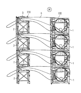
Fig. 7 shows a vertical stack of blades supported by a hold-
ing arrangement 1, 2, 3 according to an embodiment of the in-
vention. Here, four blades 6 are each held in a root frame 1,
and a tip frame 2 with tip clamp 3, and the frames 1, 2 are
stacked one above the other. The uprights of the frames 1, 2
can be secured to each other using a locking arrangement, for
example locking pins such as those shown in Fig. 5. The low-
est root frame 1 and tip frame 2 can be secured to the ground
using mounting feet 5 and locking pins, also as shown in Fig.
5. Four root frames 1 thus form a vertical root frame stack
100, while four tip frames 2 form a vertical tip frame stack
200. Such vertical stacks 100, 200 can be combined in an ar-
ray. For example, eight blades can be arranged in two verti-
CA 02849214 2014-04-17
201300255
14
cal stacked arrangements of the type shown in Fig. 7. Alter-
natively, in a very efficient arrangement, arrays of vertical
stacks 100, 200 can be "interleaved". Fig. 8 shows such an
array 300 comprising two interleaved arrays of twelve blades,
stacked in three vertical four-blade stacks 100, 200 as shown
in Fig. 7. The two twelve-blade arrays are arranged so that
the twelve blade tips of one array point toward the root ends
of the other array. This is made possible by the overall nar-
row dimensions of the tip frames 2 and root frames 1, which
do not extend to any significant extent beyond the blades
themselves. For additional stability, the uppermost root
frames 1 can be secured by struts 101 connected between the
uprights of adjacent root frames 1.
Fig. 9 shows the array 300 of Fig. 8 arranged on a container
vessel 8 for sea transport, for example to an offshore wind
park installation. The diagram illustrates that a relatively
large number of blades 6 can be accommodated on the vessel 8.
Such a vessel 8 is usually dimensioned to carry a specific
number of standard containers. A three-dimensional array of
standard containers usually fills the rectangular volume of
the loading space more or less exactly, i.e. with little or
no "room to spare" at the sides. The diagram shows that the
24-blade interleaved array fills such a rectangular volume.
This is made possible by dimensioning the root frames 1, tip
frames 2 and connecting struts 101 appropriately. For exam-
ple, the combined width of three root frames 1 and two struts
101 is chosen to correspond to an integer multiple of a con-
tainer width. Similarly, the combined width of six tip frames
2 corresponds to the same container width integer multiple.
Although the present invention has been disclosed in the form
of preferred embodiments and variations thereon, it will be
understood that numerous additional modifications and varia-
tions could be made thereto without departing from the scope
of the invention.
CA 02849214 2014-04-17
201300255
For the sake of clarity, it is to be understood that the use
of "a" or "an" throughout this application does not exclude a
plurality, and "comprising" does not exclude other steps or
elements.