Note: Descriptions are shown in the official language in which they were submitted.
CA 02849251 2014-03-19
WO 2013/028440 PCT/US2012/051019
ELECTRIC FUEL PUMP TESTER AND METHOD
CROSS REFERENCE TO RELATED APPLICATIONS
100011 None.
BACKGROUND OF THE INVENTION
Field of the Invention
100021 This invention relates generally to method for fault detecting in
electric components
located in vehicle circuits and, more particularly, to a tester device and
testing method for
testing the electrical operating characteristics of an electric fuel pump.
Related Art
100031 When a vehicle's fuel system is malfunctioning, the electric fuel pump
is often
considered first to determine whether it is defective. A common issue
encountered when
attempting to diagnose a problem with a vehicle's fuel system is that the
technician is unable
to quickly yet thoroughly test the electric fuel pump so as to either identify
it as the problem
or to rule it out. According to most prior art techniques, a technician would
test the voltage at
the fuel pump electrical connection on the vehicle wire harness. In some
cases, this was
accompanied by the laborious process of uninstalling the fuel pump from the
vehicle. If the
voltage at the electrical connection measured within an acceptable range of
the standard
operating voltage of the electrical fuel pump (commonly 12 VDC), the
technician would
conclude that the electrical system of the vehicle was operating properly and,
that the fuel
pump was defective. This conclusion commonly dictated replacing the fuel pump,
and
possibly returning the original fuel pump to its manufacturer seeking
reimbursement as a
defect.
100041 This approach often lead to an erroneous conclusion concerning the
operability of
the fuel pump. For example, if the fuel pump wire harness was defective, the
simple voltage
test might still register 12 VDC when in an unloaded state. In many reported
cases,
technicians using this simple voltage test have mistakenly replaced the fuel
pump in a vehicle
multiple times without realizing that the fuel pumps were never defective but
instead the
electrical system of the vehicle was the root cause of the problem. In each of
these instances,
substantial additional cost and inconvenience is caused to the vehicle owner,
pump
manufacturer and/or service technician due to the misdiagnosis.
1
CA 2849251 2017-03-20
[0005] A more recent prior art system and method for in situ testing the
electrical operation of
an electric fuel pump is shown in US Patent No. 7,710,121 to Harvey et al.,
issued May 4, 2010 and
assigned to the assignee of the present invention. The system and method
described in US 7,710,121
represents a significant advancement over earlier systems and methods, and has
enjoyed rapid and
widespread acceptance in the marketplace. There exists however, a continuous
desire for further
improvement to provide even more easy to use, more efficient systems and
methods for field testing the
electrical operation of an electric fuel pump.
SUMMARY OF THE INVENTION
[0006] The present invention relates to a system and method for fault
detecting in electric
components located in vehicle circuits, and more particularly for testing the
operation of an electric fuel
pump. An electric fuel pump is provided having a power supply connection for
electrically connecting
the fuel pump to a vehicular fuel system. The fuel pump includes a motor
having a commutator, a pump
armature winding interfacing with the commutator, and a coil winding circuit.
A test apparatus is
provided having a processor and a non-transitory computer readable medium.
Reference data is stored
in the non-transitory computer readable medium. The test apparatus is
electrically connected to the power
supply connection of the fuel pump. The non-transitory computer readable
medium is coded with
instructions and executed by the processor to perform the steps of: conducting
a first test, the first test
including applying a low current signal through the fuel pump power supply
connection and monitoring
for inductive reflectance from the pump armature winding in the fuel pump;
collecting data from the first
test in the non-transitory computer readable medium; conducting a second
continuity test, the second test
including checking for an open or shorted coil winding circuit in the fuel
pump; collecting data from the
second test in the non-transitory computer readable medium; comparing the
collected test data to the
stored reference data; and generating either a humanly discernable FAIL or
PASS signal in response to
the comparing step.
[0007] The present invention is capable of being field implemented as a
small,
light test unit that will quickly discern whether an electric fuel pump is
defective. The
present invention can be used to provide a preliminary assessment on fuel pump
functionality. In
2
CA 02849251 2014-03-19
WO 2013/028440 PCT/US2012/051019
other words, the present invention provides a quick, initial test device and
method for
determining that the pump is functioning properly or, in the alternative,
whether further
testing is required. Use of the invention in the trade will result in more
accurate diagnosis of
vehicular fuel system problems, and fewer erroneous returns of electrical fuel
pumps to their
manufacturers.
BRIEF DESCRIPTION OF THE DRAWINGS
[0008] These and other features and advantages of the present invention will
become more
readily appreciated when considered in connection with the following detailed
description
and appended drawings, wherein:
[0009] Figure 1 is a schematic of an electric fuel pump tester according to
one embodiment
of the present invention connected to an electric fuel pump located inside a
vehicular fuel
tank for in situ testing;
[0010] Figure 2 is a perspective view of one embodiment of the present
invention
illustrating alternative connector fittings suitable for attachment to
different makes of fuel
pumps and/or fuel pump modules;
100111 Figure 3 is a fragmentary perspective view showing the hands of a
technician
electrically connecting the test apparatus to the power supply connection of a
fuel pump;
[0012] Figure 4 is an end view of an exemplary first connector fitting for
connecting to the
power supply connection of a fuel pump originating from a first manufacturer;
[0013] Figure 5 is an end view of an exemplary second connector fitting for
connecting to
the power supply connection of a fuel pump originating from a second
manufacturer;
[0014] Figure 6 is an end view of an exemplary third connector fitting for
connecting to the
power supply connection of a fuel pump originating from a third manufacturer;
[0015] Figure 7 is a fragmentary perspective view showing a technician holding
a fuel
pump tester according to one embodiment of the present invention which, during
operation,
generates a humanly discernable FAIL signal in the foi in of an illuminated
indicator light
[0016] Figure 8 is a flow chart depicting a method of testing the operation of
an electric
fuel pump according to one embodiment of the present invention; and
[0017] Figure 9 depicts a simplified, exemplary circuit diagram for the
present test
apparatus.
3
CA 2849251 2017-03-20
DETAILED DESCRIPTION OF THE PREFERRED EMBODIMENT
[0018] Referring to the figures, wherein like numerals indicate like or
corresponding parts
throughout the several views, the present invention provides a system and
method for testing the real-
life electrical operating characteristics of a vehicle's fuel pump. A portion
of a vehicular fuel system is
generally shown at 10 in FIG. 1. In this example, the fuel system 10 includes
a tank assembly 12 of the
type commonly used for containing liquid fuel, such as gasoline, and then
supplying that fuel upon
demand to an internal combustion engine (not shown). The tank assembly 12 in
this example comprises
a thin-walled, hollow member into which liquid fuel is filled through a nozzle
14. An electric fuel pump
module, generally indicated at 16, is disposed in the tank. This example
depicts the fuel pump 16 as an
in-tank type combined within a module assembly including a float, filter and
other features. However,
the principles of this invention can be applied equally to stand-alone fuel
pumps, externally mounted fuel
pumps and related devices.
[0019] The fuel pump 16 in the in-tank style shown includes a hanger
flange 18 which seats in a
complementary-shaped opening in the top of the tank 12. The hanger flange 18
acts as a lid, connecting
the fuel pump 16 to the tank 12 and also routing fluids into and out of the
tank 12, such as fuel and vented
gases. A power supply connection 20 electrically connects the fuel pump 16 to
a vehicular fuel system.
The fuel pump 16 includes a motor (not shown) having some form of commutator,
a pump armature
winding interfacing with the commutator, and a coil winding circuit. A fuel
pump 16 according to the
subject invention can be of any known type including, for example, that
described in U.S. Pat. Nos.
7,523,745 and 7,411,326.
[0020] A test apparatus according to one embodiment of the invention is
generally shown at 22
in FIGS. 1 and 2. In this embodiment, the test apparatus 22 comprises a
lightweight, handheld device
ergonomically shaped and containing within its housing a non-transitory
computer readable medium and
a processor 40 (FIG. 9). The computer readable medium is preprogrammed with
stored reference data
relating to pump characteristics of functional units together with
predetermined ranges or variances
within which acceptable pump performance can be discerned. The test apparatus
22 preferably includes
an On/Off switch 24 ergonomically located for actuation by a person's thumb. A
Power On indicator
light 26 may be included to identify when the device is powered on, as well as
confirm that self contained
4
CA 02849251 2014-03-19
WO 2013/028440 PCT/US2012/051019
batteries 46 (Figure 9) carry a charge suitable for proper operation. PASS 28
and FAIL 30
indicator lights may be included. The PASS indicator light 28 may be designed
to render a
green colored light, whereas the FAIL indicator light 30 may be designed to
render a red
colored light. In addition or alternatively, audible, haptic or other forms of
visual indicators
can be used to distinguish between PASS and FAIL conditions.
[0021] The test apparatus 22 further includes an extension cable 32 that may
be sufficiently
long enough to enable a technician to be stationed a comfortable distance away
from the fuel
pump 16. The extension cable 32 may, for example, be approximately 15 feet
long, although
other lengths are certainly within the scope and spirit of this invention. At
the free distal end
of the extension cable 32 (i.e., opposite the end adjoining the housing) are
located at least
one, and preferably multiple connector fittings 34, 36, 38. In the example
shown in Figure 3,
three such connector fittings 34, 36, 38 are provided. Cable adaptor 34 may be
suitable for
connecting to a Ford style fuel pump 16, connector fitting 36 may be suitable
for connection
to a Chrysler style fuel pump 16 and connector fitting 38 may be configured to
attach to a
GM style fuel pump 16. These are of course examples only and the test
apparatus 22 may be
configured with additional, alternative or only one connector fitting.
Alternatively, the
connector fittings 34-38 may be disconnectable from the extension cable 32 and
separately
attached from an assortment made available to the technician via as common
adaptor or
quick-connect feature. Figures 4-6 illustrate the exemplary connector fittings
34, 36, 38 in
greater detail.
[0022] In order to perform a vehicle fuel system test using the test apparatus
22, it may be
necessary to first unplug or disconnect the power supply connection 20 from
the vehicular
fuel system prior to attaching the appropriate connector fitting 34-38 to
electrically directly
connect the test apparatus 22 to the fuel pump 16, as illustrated in Figure 3.
Once the test
apparatus 22 is directly electrically connected to the fuel pump 16, the
processor inside the
handheld housing executes instructions coded on the non-transitory computer
readable
medium also contained in the housing. As mentioned previously, the test
apparatus 22
preferably includes a self-contained electrical source which may be in the
form of a
rechargeable cell or replaceable batteries. In the example illustrated, the
battery(ies) 46 may
be located inside the housing to provide electrical power to operate the
processor and carry
out the other electronic functions.
CA 02849251 2014-03-19
WO 2013/028440 PCT/US2012/051019
100231 The instructions coded on the non-transitory computer readable medium
inside the
test apparatus 22, and executed by the processor 40, perform a series of steps
that conduct a
rapid, preliminary test to detei mine if the fuel pump 16 is electrically
and/or mechanically
functioning properly. These steps include conducting a first test in which a
low current signal
(generated by the battery 46) is applied through the fuel pump power supply
connection 20.
The apparatus 22 then monitors for inductive reflectance from the pump
armature winding in
the fuel pump 16. Depending on the reflection quality returned to the test
apparatus 22, it is
possible to assess the working condition of this portion of the fuel pump 16.
For example, if
over a succession of rapid samplings the inductive reflectance does not
change, it could
indicate a fused or jammed pump armature. Data from the first test is
collected in computer
readable medium contained in the test apparatus 22.
100241 A second test is also conducted by the apparatus 22. The second test is
a continuity
test in which a check is made for an open or shorted coil winding in the fuel
pump 16.
According to one approach, the tester 22 produces a small voltage sent through
the cable 32
to the power supply connection 20, to determine whether current flows through
the coil
windings in the motor. Data from the second test is also collected in the test
apparatus 22.
The processor further executes instructions coded in the computer readable
medium so as to
conduct a third test with test apparatus 22. The third test applies a higher
power, short
duration pulse through the pump electrical connections 20 to create a
rotational movement of
the pump armature which is keyed to the pump's pumping section (not shown).
This third
test uses power supplied from the self-contained power source 46 (e.g., a
single 9 VDC
battery or three AAA cells) to detect both mechanical and electrical issues.
Mechanical
issues can include potentially locked pumping sections within the pump 16
and/or high
frictional loads which may, for example, be caused by bad bearings or trapped
debris.
Electrical issues can include excessive current draw or alternatively low
current draw. Data
from the third test is collected in the test apparatus 22.
[0025] Preferably, although not necessarily, these first, second and third
tests are repeated
for each interface of the commutator and pump armature coil winding in the
motor. In this
way, each interface can be tested with the same first, second and third tests,
with the data
being collected as described in a computer readable medium within the hand-
held unit. Once
these tests are completed, the collected test data is compared to the stored
reference data in
the computer readable medium. Such comparisons preferably include reference to
a pre-
6
CA 02849251 2014-03-19
WO 2013/028440 PCT/US2012/051019
established threshold range within which the pump 16 will be deemed to pass or
conform to
acceptable standards. Outside the threshold range, however, the pump 16 will
be deemed to
fail or represent a potentially defective pump 16. In response to this
comparison step, the
processor executes additional instructions which generate either a FAIL or
PASS signal
which may be carried out through the indicator lights 28, 30 or by other
suitable means.
[0026] A fourth, optional test may be carried out to provide additional
information about
the operating characteristics of the pump 16. This fourth test includes
attaching the power
supply connection 20 of the fuel pump 16 to a 12-volt DC power source such as
the vehicle
battery (or other power source suitable to run the pump 16). The fuel pump 16
is then
energized via the power source (e.g., the vehicle battery) to operate the pump
16 under test,
with a short run time current wave form being captured in the computer
readable medium.
This current wave form can likewise be compared to reference pump data sets as
previously
described and used as an indicator of its operation condition. Figure 8 is a
generalized flow
diagram representing the operational steps as described above.
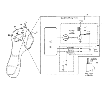
[0027] An electrical circuit configured to carry out the methods of this
invention, according
to one exemplary embodiment, is depicted in Figure 9. In this example, a micro-
controller
includes a build-in processor 40 and is used to drive a charge pump circuit 42
as well as the
base of a trace circuit 44. The micro-controller 40 is preferably a Digital
Signal Processor.
In this particular example, the charge pump circuit 42 is used to carry out
the second
(continuity) and third (mechanical & electrical issues) test, whereas the
trace circuit 44 is
used to carry out first (inductive reflectance) test. The battery 46 is here
shown as a 9 VDC,
which may be of the standard PP3 type commonly used in hand held electronic
devices.
Naturally, a electrical engineer of skill in the circuit designing arts will
envision alternative
circuit constructions that may be implemented to accomplish the methods of
this invention.
In other words, the specific circuit diagram in Figure 9 is not intended to be
limiting but
rather exemplary in nature.
[0028] According to the methods described herein, the subject test apparatus
22 can be
configured in the form of a hand-held, portable device that can be
conveniently used by
service technicians to perform a preliminary test of a fuel pump 16 in the
field to determine if
the fuel pump 16 is truly defective. The test apparatus 22 may take various
physical forms
not limited to those illustrated in the drawings. The apparatus 22 is
connected directly to the
fuel pump 16 and configured to perfoi in at least two, and preferably
three, and more
CA 02849251 2014-03-19
WO 2013/028440 PCT/US2012/051019
preferably four, tests to determine pump electrical and mechanical integrity.
The first test is
carried out by applying a low voltage low current signal through the pump
positive
connection and then monitoring for an inductive reflectance from the pump
armature
winding. The second test comprises a continuity test through the pump
electrical connections
20 to check for an open or shorted coil winding circuit that would not be
absolutely detected
in the first test. The third test is carried out by applying a higher power
but short duration
pulse through the pump electrical connection 20 to create some rotational
movement of the
pump armature keyed into the pumping section itself. This third test is
configured to detect
locked pumping sections (mechanical issue), high frictional load (mechanical
issue),
excessive current draw (electrical issue), low current draw (electrical
issue), and possibly
other issues. The first, second and third tests may be repeated to test each
pump armature
coil winding commutator interface. In addition, a short run period of the pump
may be added
which would require the test apparatus 22 to be attached to an external 12-
volt DC battery to
provide adequate power to run the pump 16 under test, thereby allowing the
test apparatus 22
to capture a short run time current waveform. The apparatus 22 is programmed
with
reference pump data sets used to pass or fail pump functions that are checked
during the
separate tests. The subject test apparatus 22 thus checks pump 16
functionality in an
unloaded condition and does not require testing the pump 16 with gasoline or a
calibration
fluid.
[0029] The present invention represents a unique and effective vehicle fuel
pump 16 testing
device 22 that is capable of applying a test load to a suspectedly failed pump
16 while
checking for a combination of mechanical and electrical defects. The subject
apparatus 22
benefits service technicians as well as manufacturers by providing a fast and
simple
diagnostic tool capable of checking fuel pump 16 integrity. Such a device 22
will help to
reduce fuel pump warranty claims by allowing technicians and customers, part
stores, counter
personnel, professional mechanics and others to check fuel pump integrity and
prevent good,
functional fuel pumps from being claimed as defective.
[0030] The foregoing invention has been described in accordance with the
relevant legal
standards, thus the description is exemplary rather than limiting in nature.
Variations and
modifications to the disclosed embodiment may become apparent to those skilled
in the art
and fall within the scope of the invention.
8