Note: Descriptions are shown in the official language in which they were submitted.
CA 02849445 2014-02-26
WO 2013/040317
PCT/US2012/055349
SINGLE STEP SHAPE MEMORY ALLOY EXPANSION
BACKGROUND OF THE INVENTION
[0001] It is well known to employ various intravascular endoprostheses
delivered percutaneously for the treatment of diseases of various body
vessels.
These types of endoprostheses are commonly referred to as stents. A stent is
generally a tubular device formed of a biocompatible material such as nitinol.
The
fabrication of stents from nitinol tubes that are cut by such methods as laser
cutting,
water jet cutting, electrical discharge maching, and chemical milling is
commonly
known. Nitinol is considered a shape memory alloy (SMA). Nitinol also has a
shape
setting temperature, defined as any temperature within the temperature range
at
which a shape memory alloy (SMA) article, when exposed to for a period of time
in a
constrained shape, will substantially maintain the constrained shape when the
article
is subsequently unconstrained.
[0002]The manufacturing of nitinol tubes is expensive. The larger the
diameter of the nitinol tube the more expensive it becomes. The cost
constraints of
large diameter nitinol tubing have resulted in the practice of cutting
patterns (such as
stent patterns) into small diameter nitinol tubes and then incrementally
expanding
and shape setting these tubes to attain larger diameter nitinol tubes (and/or
nitinol
stents).
[0003]One general method of shape setting nitinol involves deforming and
constraining the nitinol in a desired shape at room temperature (usually about
20 C)
or at below room temperature. The nitinol is then exposed to an elevated
temperature (usually about 500 C) while constrained in a desired shape, in a
furnace for example, for a period of time (usually about 5 to 20 minutes). The
nitinol
is then cooled to room temperature by either water quenching or allowing the
nitinol
to air cool. This shape setting process imparts a new shape to the nitinol.
The new
shape is a result of the specific prior deformation and constraining of the
cut tube.
[0004]In the case of expansion of a cut nitinol tube, a series of incremental
expansion and shape setting steps are commonly used. The traditional method
for
nitinol stent device manufacturing is described by Poncin et. al. (SMST-2000
Conference Proceedings, pp 477-486) which states "[t]he device is expanded to
its
final size by a succession of progressive, shape-setting steps involving heat
1
CA 02849445 2014-02-26
WO 2013/040317
PCT/US2012/055349
treatments." Using a series of incremental expansion steps reduces the
incidence of
fracture or cracking of the cut nitinol tube during shape setting.
[0005] In one example, a stent pattern can be laser cut into a nitinol tube
having an outer diameter of about 4 mm. In order to expand this 4 mm cut tube
to a
24 mm cut tube, a series of incremental expansion steps would be taken. For
example: the cut nitinol tube would be expanded from a 4 mm diameter to an 8
mm
diameter and then shape set; next, the cut nitinol tube would then be expanded
from
8 mm to 12mm diameter and then shape set; and so on until the desired 24 mm
diameter cut tube is attained.
[0006] It is common practice to utilize a series of expansion steps in stent
forming to avoid stent fracture during the shape setting process. The above
example
utilized five expansion steps to attain the desired stent diameter of 24mm.
Omitting
even one of these expansion steps, expanding from 4mm to 12mm and shape
setting for example, can result in the stent fracturing during shape setting.
This
process of forming nitinol incrementally through a series of shape setting
steps is
costly and time consuming.
[0007] It is also common practice for those skilled in the art to cool nitinol
stents, forming thermally induced martensite prior to the expansion of a
nitinol tube.
Nitinol tubes that are primarily austenite at room temperature will be easier
to deform
and diametrically expand if they are first cooled to form thermally induced
martensite.
Because martensitic nitinol is easier to deform than austenitic nitinol, it
has been
assumed that forming thermally induced martensite prior to expanding a nitinol
tube
will minimize crack formation in the stent. In spite of this practice of
thermally
inducing martensite prior to nitinol tube expansion, crack formation during
expansion
of nitinol tubes is a problem. The practice of thermally inducing martensite
prior to
nitinol tube expansion has not eliminated the need for incremental expansion
steps
required to diametrically expand and shape set nitinol tube.
[0008] Therefore, there has been a need to have a nitinol medical device
forming process that overcomes the disadvantages of the prior art. The present
invention provides such a solution.
2
CA 02849445 2014-02-26
WO 2013/040317
PCT/US2012/055349
SUMMARY OF THE INVENTION
[0009]In accordance with the present invention, there is provided a method of
forming nitinol. In one embodiment, nitinol is exposed to a shape setting
temperature of at least 300 C to about 6500 C in an unstrained or minimally
strained
condition. The nitinol is then substantially deformed in shape while at this
elevated
temperature. After deformation, the nitinol is retained at the elevated
temperature
while constrained in the desired shape for a time to shape set the material.
In
another embodiment, the nitinol may be deformed once or more than once while
at
the elevated temperature. The nitinol is then returned to approximately room
temperature (about 20 C), by means of water quenching and/or air cooling for
example while still being constrained.
[0010]Thus, one embodiment of the invention comprises a method of forming
a shape memory alloy (SMA) article, comprising, providing a SMA article having
an
initial shape, said SMA having a shape setting temperature, heating the SMA
article
to about said shape setting temperature, deforming the SMA article while at
about its
shape setting temperature to a final shape, and cooling the SMA article while
being
constrained thereby substantially retaining said final= shape. In one
embodiment,
after deforming said SMA article while at about its shape setting temperature,
allowing said deformed SMA article to dwell while at about its shape setting
temperature. In another embodiment, said shape setting temperature is about
300
C to about 650 C. In another embodiment, said SMA is nitinol. In another
embodiment, deforming said SMA article into said final shape is accomplished
by
application of an internal force. In another embodiment, deforming said SMA
article
into said final shape is accomplished by application of an external force. In
another
embodiment, said deforming SMA article into said final shape is accomplished
by
use of a tapered mandrel. In another embodiment, said SMA article is shaped
into a
medical device. In another embodiment, said medical device is an implantable
device. In another embodiment, said implantable device is selected from the
group
consisting of a stent, cardiac occluder, valve, and an intraluminal filter. In
another
embodiment, said SMA initial shape was formed by machining. In another
embodiment, said machining comprises laser cutting, water jet cutting,
electrical
discharge machining, and/or chemical etching.
[0011]Another embodiment of the invention comprises a method of forming a
stent, comprising, providing a machined shape memory alloy (SMA) tube, wherein
3
CA 02849445 2014-02-26
WO 2013/040317
PCT/US2012/055349
said machined SMA tube comprises: a stent pattern, a first (smaller) diameter,
and a
shape setting temperature, heating said machined SMA tube to about said shape
setting temperature, deforming said machined SMA tube while at about its shape
setting temperature to a second (larger) diameter and cooling the SMA article
while
being constrained thereby substantially retaining said second diameter. In one
embodiment, said machining comprises laser cutting, water jet cutting,
electrical
discharge machining and/or chemical etching. In another embodiment, said stent
pattern comprises a sinusoidal shape, a diamond shape, a U shape, a V shape or
an
ovaloid shape. In another embodiment, said SMA tube has a circular cross-
section.
In another embodiment, after deforming said SMA tube while at about its shape
setting temperature, allowing said deformed SMA tube to dwell. In another
embodiment, said shape setting temperature is about 300 C to about 650 C. In
another embodiment, deforming said SMA tube into said second shape is
accomplished by application of an internal force. In another embodiment,
deforming
said SMA tube into said second shape is accomplished by application of an
external
force. In another embodiment, said deforming SMA tube into said second shape
is
accomplished by use of a tapered mandrel. In another embodiment, the ratio of
the
second (larger) diameter shape to the first (smaller) diameter shape is
greater than
about 1.25:1 In another embodiment, the ratio of the second (larger) diameter
'shape to the first (smaller) diameter shape is greater than about 1.5:1. In
another
embodiment, the ratio of the second (larger) diameter shape to the first
(smaller)
diameter shape is greater than about 2:1. In another embodiment, the ratio of
the
second (larger) diameter shape to the first (smaller) diameter shape is
greater than
about 3:1. In another embodiment, the ratio of the second (larger) diameter
shape to
the first (smaller) diameter shape is greater than about 4:1.
[001 2] In another embodiment, the invention comprises a medical device,
comprising a shape memory alloy (SMA) article tailored to transition between a
first,
second and third state, wherein said SMA comprises a shape setting
temperature,
wherein, the article in a first state comprises a first circumferential
perimeter, the
article in a second state comprises multiple circumferential perimeters, the
article in
a third state comprises a third circumferential perimeter, wherein each of
said
second state circumferential perimeters are larger than the first state
circumferential
perimeter and smaller than the third state circumferential perimeter and
wherein the
4
CA 02849445 2014-02-26
WO 2013/040317
PCT/US2012/055349
shape memory alloy (SMA) article is kept at said shape setting temperature
while
transitioning between the first, second and third states.
[0013]Another embodiment of the invention comprises a device for deforming
a SMA article, comprising a slotted elongated tube comprising; i. a
longitudinal axis
and a first outer perimeter, ii. the tube having a length, a through lumen and
a wall,
iii. the lumen defining a first inner perimeter, iv. the tube having at least
two slots
through the wall, v. the slots being oriented essentially parallel to the tube
longitudinal axis, vi. the slots extending partially along the tube length; an
expansion
mandrel comprising, i. a first portion with an essentially constant first
perimeter, ii. a
second tapered portion, iii. the second tapered portion having a varying
perimeter
transitioning from the mandrel first perimeter to a larger second perimeter,
iv. the
mandrel first portion perimeter being dimensioned to be inserted into the
lumen first
inner perimeter of said slotted elongated tube; and a shape memory alloy
article
surrounding at least a portion of said slotted elongated tube. In one
embodiment,
said SMA is nitinol. In another embodiment, said SMA article is a medical
device. In
another embodiment, said medical device is selected from the group consisting
of a
stent, cardiac occluder, valve, and an intraluminal filter.
[0014]Another embodiment of the invention comprises a device for deforming
a SMA article, comprising a slotted elongated tube comprising, i. a
longitudinal axis
and a first outer perimeter, ii. the tube having a length, a through lumen and
a wall,
Ýii. the lumen defining a first inner perimeter, iv. the tube having at least
two slots
through the wall, v. the slots being oriented essentially parallel to the tube
longitudinal axis, vi. the slots extending partially along the tube length; an
expansion
mandrel comprising, i. a first portion with an essentially constant first
perimeter, ii. a
second tapered portion, iii. the second tapered portion having a varying
perimeter
transitioning from the mandrel first perimeter to a larger second perimeter,
iv. the
mandrel first portion perimeter being dimensioned to be inserted into the
lumen first
inner perimeter of said slotted elongated tube; wherein the slotted elongated
tube
surrounds at least a portion of the expansion mandrel and a SMA article
surrounding
at least a portion of said slotted elongated tube. In one embodiment, the
slotted
elongated tube surrounds at least a portion of the expansion mandrel first
portion. In
another embodiment, the slotted elongated tube surrounds at least a portion of
the
expansion mandrel second tapered portion. In another embodiment, the expansion
mandrel further comprises a third portion having an essentially constant
second
CA 02849445 2014-02-26
WO 2013/040317
PCT/US2012/055349
perimeter. In another embodiment, the slotted elongated tube surrounds at
least a
portion of the expansion mandrel third portion.
[0015]Another embodiment of the invention comprises a device for deforming
a shape memory alloy (SMA) article, comprising, a slotted elongated tube
comprising, i. a longitudinal axis and a first outer perimeter, ii. the tube
having a
length, a through lumen and a wall, iii. the lumen defining a first inner
perimeter, iv.
the tube having at least two slots through the wall, v. the slots being
oriented
essentially parallel to the tube longitudinal axis, vi. the slots extending
partially along
the tube length, vii. the tube having a first portion with an essentially
constant first
perimeter, viii. the tube having a second tapered portion, ix. the second
tapered
portion having a varying perimeter transitioning from the tube first perimeter
to a
larger second perimeter; and a translating device comprising, i. a rod sized
to extend
and slide through the slotted elongate tube through lumen, ii. the rod having
at least
two fins sized to extend and slide through said slots through the wall of the
slotted
elongated tube, a SMA article surrounding at least a portion of said slotted
elongated
tube.
[0016]Thus, in accordance with the methods of present invention, a nitinol
tube (e.g. a stent) can be expanded to a much larger diameter (e.g. 6X or
more) in a
single processing step.
BRIEF DESCRIPTION OF THE DRAWINGS
[0017]The exemplary embodiments of the present invention will be described
in conjunction with the accompanying drawings in which, where appropriate,
like
numerals denote like elements and are offset by 100. The accompanying drawings
are included to provide a further understanding of the invention and are
incorporated
in and constitute a part of this specification, illustrate embodiments of the
invention
and together with the description serve to explain the principles of the
invention.
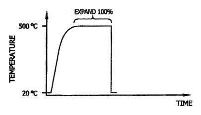
[0018]Figure 1 is a Time/Temperature graph displaying a multi-step heat
forming process as currently known in the art.
[0019]Figure 2 is Time/Temperature graph displaying a single-step heat
forming process according to the present invention.
[0020]Figure 3A and 3B are perspective drawings of a cut pattemed tube
before and after expansion.
6
CA 02849445 2014-02-26
WO 2013/040317
PCT/US2012/055349
[0021]Figure 4 is a perspective view of an expansion fixture of the present
invention, showing a slotted mandrel, expander die, and pull rod.
[0022]Figure 5A is a side-view of a stent expansion mandrel assembly of the
present invention, showing a slotted mandrel, expander die, pull rod, and
stent.
[0023]Figure 5B is a side-view of a stent expansion mandrel assembly of the
present invention, showing a slotted mandrel, expander die, pull rod, and a
stent.
[0024] Figure 5C is a side-view of a stent expansion mandrel assembly of the
present invention, showing a slotted mandrel, expander die, pull rod, and a
partially
expanded stent.
[0025]Figure 5D is a side-view of a stent expansion mandrel assembly of the
present invention, showing a slotted mandrel, expander die, pull rod, and a
fully
expanded stent.
[0026]Figure 5E is a side-view of a stent expansion mandrel assembly of the
present invention, showing a slotted mandrel and a fully expanded stent.
Figure 6A is a perspective view of a slotted tube of the present invention.
[0027]Figure 6A is a perspective view of a slotted tube of the present
invention and an unexpanded stent.
[0028]Figure 6B is a perspective view of a tapered mandrel of the present
invention.
[0029]Figure 6C is a perspective view of a stent expansion mandrel assembly
of the present invention, showing a slotted tube, tapered mandrel, and an
unexpanded stent.
[0030]Figure 6D is a perspective view of a stent expansion mandrel assembly
of the present invention, showing a slotted tube, tapered mandrel, and an
expanded
stent.
DETAILED DESCRIPTION OF THE INVENTION
[0031]As currently known in the art, Mind tubes having various diameters
and wall thicknesses can be cut to form a desired pattern, such as a stent
pattern.
The cut tube may be placed onto an expansion fixture and expanded by about 20%
while at ambient temperature. The cut tube and the expansion fixture may be
then
heated to an elevated temperature and after an appropriate dwell time, the cut
tube
and fixture can be quenched to return the cut tube to an ambient temperature.
This
7
CA 02849445 2014-02-26
WO 2013/040317
PCT/US2012/055349
process may be repeated with each cycle expanding the tube an additional about
20% resulting in a desired diameter (i.e. 100% expansion).
[0032] Shown in Figure 1 is a Time/Temperature graph displaying a typical
expansion process as commonly known in the art. In this example, a five step
expansion process is shown, wherein each expansion occurs at about ambient
temperature (about 20 C). Each of the five expansion steps expands the cut
tube by
about 20% of its expanded diameter. After each expansion, the cut tube and
expansion fixture are heated to about 500 C and after an appropriate dwell,
the cut
tube and expansion fixture are water quenched, returning the cut tube and
expansion fixture to ambient temperature. As shown, the process is repeated
four
additional times, resulting in a desired diameter (total expansion of about
100%).
[0033] Figure 2 is a graph (having the same axes as Figure 1), depicts a
process that expands a cut tube to the desired diameter (i.e. about 100%
expansion)
in a single expansion step. As shown in Figure 2, a cut tube is placed onto an
expansion fixture. The cut tube and the expansion fixture can then be heated
to an
elevated temperature and while at this elevated temperature, the expansion
fixture
can be activated to expand the cut tube by about 100% in a single expansion
step.
In another embodiment, said expansion fixed can be activated to expand the cut
tube by about 200%, about 300%, about 400% and/or about 500%. By comparing
Figure 1 with Figure 2, it appreciated that the method taught herein reduces
the
amount of steps, and thus time, to expand a nitinol tube.
[0034] Figure 3A is a partial perspective view of a typical cut tube 300a,
having an initial small diameter 302. The cut tube 300a has an undulating
shape,
typical of an implantable stent, comprising peaks 304 and valleys 306. Figure
3B is a
partial perspective view of the expanded cut tube 300b after being expanded to
a
larger diameter 308. The larger diameter 308 is about 100% greater than the
initial
small diameter 302. The tube 300a can be cut to have any desired pattern. For
example the tube 300a can be cut to form individual rings, interconnected
rings,
open and/or closed cells, or shapes such as a sinusoidal shape, a diamond
shape, a
U shape, a V shape or an ovaloid shape or any other pattern tailored for a
given
application. The tube 300a can comprise nitinol or any other similar metal
having a
shape setting temperature range. Nitinol refers to the family of alloys that
include
binary nickel- titanium binary shape memory alloys as well as nickel-titanium
based
alloys including temary and quaternary additions of alloying elements such as
but
8
CA 02849445 2014-02-26
WO 2013/040317
PCT/US2012/055349
not limited to iron, niobium, chromium, copper, cobalt, vanadium, platinum,
and
hafnium. Shape memory alloys include nitinol alloys as well as other alloys
that are
capable of undergoing a reversible crystallographic phase change such as, but
not
limited, to AgCd, AuCd, CuAlZn, CuAlNi, CuAlBe, CuSn, NiAl, FePt, FePd, MnCu,
and FeMnSi alloy systems.
[0035]The tube 300a can have diameters ranging from about 0.5mm to about
100mm with a preferred range of about 2mm to about 40mm. The tube 300a can
have a wall thickness ranging from about 0.05mm to about 10mm with a preferred
range of about 0.1mm to about 0.5mm. The length of tube 300a can range from
about 1mm to about 250mm. The length of tube 300a can be configured in
accordance with any specific application.
[0036] Shown in Figure 4 is a perspective view of at least one expansion
fixture 400. In this example, the expansion fixture 400 comprises a tapered,
slotted,
tubular mandrel 402 fabricated from a high temperature metal such as Inconel,
stainless steel or other suitable material. The slotted mandrel 402 has a
large
diameter portion 404, an intermediate tapered portion 406, a small diameter
portion
408 and a series of longitudinal slots 410. The longitudinal slots 410 are cut
through
mandrel wall and extend through the small diameter and tapered portions (408
and
406) of the slotted mandrel. The longitudinal slots 410 are cut through
mandrel wall
and only partially extend along the large diameter portion 404, as shown in
Figure 4.
In an optional configuration, the longitudinal slots can form a spiral. The
intermediate
tapered portion can optionally have varied taper angles or acute portions in
place of
a constant taped angle.
[0037] The expansion fixture 400 further comprises an expander die 412
having a series of fins 414, as shown in Figure 4. The fins 414 of the
expander die
412 engage with the slots 410 of the slotted mandrel 402 allowing the fins 414
of the
expander die to slide through the longitudinal slots 410 of the slotted
mandrel 402,
along a longitudinal axis as depicted by direction arrow 416.
[0038] As further shown in Figure 4, the expander die 412 is joined to a pull
rod 418. The pull rod 418 extends through a center bore of the tubular slotted
mandrel 402 and extends out of a collar portion 422 of the slotted mandrel
402.
When the pull rod 418 is pulled along a longitudinal axis, depicted by
direction
arrows 416, 420, the expander die 412 is forced to slide over the small
diameter
9
CA 02849445 2014-02-26
WO 2013/040317
PCT/US2012/055349
portion 408, the intermediate tapered portion 406 and the large diameter
portion 404
of the slotted mandrel 402.
[0039]A collar portion 422 of the slotted mandrel 402 is configured to affix
the
slotted mandrel to a heating source (not shown). The slotted mandrel 402 and
expander die 412 are positioned within the heating source. The heating source
is
configured to allow the end of the pull rod 424 (opposite the expander die) to
protrude out of the heating source.
[0040]Thus, another embodiment of the invention comprises a device for
deforming a shape memory alloy (SMA) article, comprising a slotted elongated
tube
comprising; i. a longitudinal axis and a first outer perimeter, ii. the tube
having a
length, a through lumen and a wall, iii. the lumen defining a first inner
perimeter, iv.
the tube having at least two slots through the wall, v. the slots being
oriented
essentially parallel to the tube longitudinal axis, vi. the slots extending
partially along
the tube length; an expansion mandrel comprising, i. a first portion with an
essentially constant first perimeter, 11. a second tapered portion, iii. the
second
tapered portion having a varying perimeter transitioning from the mandrel
first
perimeter to a larger second perimeter, iv. the mandrel first portion
perimeter being
dimensioned to be inserted into the lumen first inner perimeter of said
slotted
elongated tube; and a shape memory alloy article surrounding at least a
portion of
said slotted elongated tube. In one embodiment, said SMA is nitinol. In
another
embodiment, said SMA article is a medical device. In another embodiment, said
medical device is selected from the group consisting of a stent, cardiac
occluder, and
an intraluminal filter.
[0041]Another embodiment of the invention comprises a device for deforming
a shape memory alloy (SMA) article, comprising a slotted elongated tube
comprising,
i. a longitudinal axis and a first outer perimeter, il. the tube having a
length, a through
lumen and a wall, iii. the lumen defining a first inner perimeter, iv. the
tube having at
least two slots through the wall, v. the slots being oriented essentially
parallel to the
tube longitudinal axis, vi. the slots extending partially along the tube
length; an
expansion mandrel comprising, i. a first portion with an essentially constant
first
perimeter, ii. a second tapered portion, iii. the second tapered portion
having a
varying perimeter transitioning from the mandrel first perimeter to a larger
second
perimeter, iv. the mandrel first portion perimeter being dimensioned to be
inserted
into the lumen first inner perimeter of said slotted elongated tube; wherein
the slotted
CA 02849445 2014-02-26
WO 2013/040317
PCT/US2012/055349
elongated tube surrounds at least a portion of the expansion mandrel and a
shape
memory alloy article surrounding at least a portion of said slotted elongated
tube. In
one embodiment, the slotted elongated tube surrounds at least a portion of the
expansion mandrel first portion. In another embodiment, the slotted elongated
tube
surrounds at least a portion of the expansion mandrel second tapered portion.
In
another embodiment, the expansion mandrel further comprises a third portion
having
an essentially constant second perimeter. In another embodiment, the slotted
elongated tube surrounds at least a portion of the expansion mandrel third
portion.
[0042]Another embodiment of the invention comprises a device for deforming
a shape memory alloy (SMA) article, comprising, a slotted elongated tube
comprising, i. a longitudinal axis and a first outer perimeter, ii. the tube
having a
length, a through lumen and a wall, iii. the lumen defining a first inner
perimeter, iv.
the tube having at least two slots through the wall, v. the slots being
oriented
essentially parallel to the tube longitudinal axis, vi. the slots extending
partially along
the tube length, vii. the tube having a first portion with an essentially
constant first
perimeter, viii. the tube having a second tapered portion, ix. the second
tapered
portion having a varying perimeter transitioning from the tube first perimeter
to a
larger second perimeter; and a translating device comprising, i. a rod sized
to extend
and slide through the slotted elongate tube through lumen, II. the rod having
at least
two fins sized to extend and slide through said slots through the wall of the
slotted
elongated tube, a SMA article surrounding at least a portion of said slotted
elongated
tube.
[0043]Any suitable heating source can be used to heat the expansion fixture
400, including fluidized baths, salt baths, high temperature liquids, high
temperature
gasses, radiant heating, inductive heating, convection heating, electrical
resistance
heating, radio frequency heating, conduction heating or by combinations of
different
energy sources.
(0044] Thus, one embodiment of the invention comprises a process for
expanding a cut tube, comprising the steps of: cutting a metallic tube to form
a
desired cut pattem; placing the cut metallic tube onto a small diameter
portion of a
slotted tapered mandrel; inserting a pull rod with an attached expander die
through a
center bore of the slotted tapered mandrel; engaging a series of fins
(integral to the
expander die) into the slots of the tapered mandrel; placing the cut tube, the
slotted
tapered mandrel and the expander die into a heating source, so that an end of
the
11
CA 02849445 2014-02-26
WO 2013/040317
PCT/US2012/055349
pull rod extends out of the heating source; heating the cut tube, the slotted
tapered
mandrel and the expander die to an elevated temperature (shape setting
temperature); translating the pull rod (while maintaining the shape setting
temperature of the cut tube, the slotted tapered mandrel and the expander die)
to
force the expander die to slide over the small diameter portion, a tapered
portion and
a larger diameter portion of the slotted tapered mandrel, wherein the fins of
the
expander die engage the cut SMA tube and force the cut SMA tube over the small
diameter portion, the tapered portion and the larger diameter portion of the
slotted
tapered mandrel as the pull rod is translated.
[0045]One process for expanding a cut SMA tube according to the present
invention is outlined in Figures 5A through 5E. Shown in Figure 5A is an
expansion
fixture 500. The expansion fixture 500 comprises a tapered, slotted, tubular
mandrel
502. The slotted mandrel 502 has a large diameter portion 504, an intermediate
tapered portion 506, a small diameter portion 508 and a series of longitudinal
slots
510. The longitudinal slots 510 are cut through mandrel wall and extend
through the
small diameter and tapered portions (508 and 506) of the slotted mandrel. The
longitudinal slots 510 are cut through mandrel wall and only partially extend
along
the large diameter portion 504, as shown in Figure 5A.
[0046]A cut tube 524a having an initial small diameter is placed over the
small diameter portion 508 of the slotted mandrel 502.
[0047]An expander die 512 having a series of fins (414 of Figure 4)
configured to engage with the slots 510 of the slotted mandrel 502 is joined
to a pull
rod 518. The pull rod 518 extends through a center bore of the tubular slotted
mandrel 502 and extends out of the slotted mandrel end that is opposite of the
expander die.
[0048]As shown in Figure 5B, the pull rod 518 is translated in the direction
indicated by arrow 520, causing the expander die 512 to advance and allowing
the
expander die fins (414 of Figure 4) to engage the slots 510 of the slotted
mandrel
502.
[0049]The expansion fixture with the cut tube is then put onto a heating
chamber (not shown) so that the collar portion 522 and the protruding pull rod
518
are outside of the heated chamber (indicated by direction arrow 525), while
the
remaining portions of the slotted mandrel 502, expander die 512 and cut tube
524a
are exposed to the heated area of the heating chamber (indicated by direction
arrow
12
CA 02849445 2014-02-26
WO 2013/040317
PCT/US2012/055349
526). The temperature of the heating chamber is then be elevated to the
desired
temperature. If a salt bath or similar heat transfer medium is used, the
medium can
be pre-heated or fully heated to the desired elevated temperature.
[0050]As shown in Figure 5C, after an appropriate dwell within the heated
chamber, the pull rod 518 is further advanced along direction 520 causing the
expander die 512 to force the cut tube 524b over the tapered portion 506 of
the
slotted mandrel 502.
[0051]As shown in Figure 5D, the pull rod 518 is further advanced along
direction 520 causing the expander die 512 to force the cut tube 524c over the
large
diameter portion 504 of the slotted mandrel 502. The translation of the pull
rod 518
can comprise a continuous motion, an intermittent motion or variable speed
motion.
[0052]The expansion fixture 500 with the fully expanded cut tube 524c is then
removed from the heating chamber. The pull rod 518 and expander die 512 are
withdrawn from the slotted mandrel 522. The slotted mandrel 502 and fully
expanded
cut tube 524c are then quenched in an ambient temperature water bath. After
reaching ambient temperature, the fully expanded cut tube 524c can be removed
from the slotted mandrel 502.
[0053] Although the Figures 5A through 5E describe a small length tube, any
length of tubing can be expanded using the above process. The large diameter
portion 404, 504 of the slotted mandrel 402, 502 can be any size to
accommodate
any length tube.
[0054]The process describe in Figures 5A through 5E is one way of using an
internal force (internal to the tube to be expanded) to expand a SMA tube,
other
methods can be used. These include an expanding mandrel that expands a tube
laid over said mandrel.
[0055]Another embodiment, expansion of a cut SMA tube accomplished by
application of an external force, pulling the tube open. Hooks or clamps that
grab
specific areas of the tube can pull the tube open to expand the tube.
[0056]While particular embodiments of the present invention have been
illustrated and described herein, the present invention should not be limited
to such
illustrations and descriptions. It should be apparent that changes and
modifications
may be incorporated and embodied as part of the present invention within the
scope
of the following claims. The following examples are further offered to
illustrate the
present invention.
13
CA 02849445 2014-02-26
WO 2013/040317
PCT/US2012/055349
EXAMPLES
EXAMPLE 1: Loading and Expanding a Cut Nitinol Tube on a Slotted Mandrel
(0057M nttinol stent ring 524a as illustrated in Figures 5A and 5B was
obtained. The stent ring 524a was laser cut from a nitinol tube having an
inner
diameter (ID) of about 4 mm and a wall thickness of about 0.5 mm. The length
of the
stent ring 524a was about 10 mm.
[0058]As shown in Figure 4, a tapered, slotted mandrel 402 made from a
suitable high temperature steel was custom fabricated. The large diameter 404
of the
slotted mandrel 402 was about 26 mm. The small diameter 408 of the slotted
mandrel 402 was about 8 mm. The length of the slotted mandrel 402 was about 11
cm. An expander die 412 made from a suitable high temperature steel was custom
fabricated.
(0059]The expander die 412 was designed in such a way that the fins 414 of
the die engaged with the slots 410 of the slotted mandrel 402 allowing the
expander
die 412 to slide through the slotted mandrel 402.
[0060]The expander die 412 is attached by such means as laser welding for
example to the pull rod 418. The pull rod 418 has a diameter of about 2mm, a
length
of about 60cm, and is fabricated from a suitable high temperature steel. A
fluidized
bath (Techne Fluidized Bath Model FB-08) used for heat treating parts was
obtained.
(0061]As shown in Figure 5A, the stent ring 524a was loaded onto the small
diameter 508 of the slotted mandrel 502. In order to load the about 4 mm ID
stent
ring 524a onto the about 8 mm small diameter 508 end of the slotted mandrel
502,
the stent ring 524a was first expanded up to about 8 mm using a tapered
mandrel
having a diameter of about 4 mm on one end and a diameter of about 8 mm on the
opposite end (at room temperature). At this point, the stent is minimally
constrained
(or substantially unconstrained). The about 8 mm end of the tapered mandrel
was
then butted up against the about 8mm small diameter 508 end of the slotted
mandrel
502 and the stent ring 524a was transferred from the tapered mandrel to the
slotted
mandrel 502 at room temperature. The pull rod 518 with attached expander die
512
was inserted through the slotted mandrel as illustrated in Figure 5A. The fins
414
(Figure 4) of the expander die 512 were engaged with the slots 510 of the
slotted
mandrel 502 as illustrated in Figure 5B.
14
CA 02849445 2014-02-26
WO 2013/040317
PCT/US2012/055349
[0062] The assembly of the slotted mandrel 502, stent ring 524a, expander die
512, and pull rod 518 were then submerged into the fluidized bath, pre-heated
to a
temperature of about 550 C, and allowed to dwell for about three minutes.
After
about 3 minutes the pull rod 518 was pulled up from the position illustrated
in Figure
5B to the position illustrated in Figure 5D. It took about two seconds of time
to pull
the pull rod 518 up from the position illustrated in Figure 5B to the position
illustrated
in Figure 5D. As upward force is applied to the pull rod 518, the fins 414
(Figure 4)
of the attached expander die 512 exert force on the stent ring 524b pulling it
up the
slotted mandrel 502 as illustrated in Figure 5C. The orientation of the slots
510 and
the fins 414 (Figure 4) also serve to maintain even diametric expansion of the
stent
ring 524c as illustrated in Figure 5D. After about 15 minutes of dwell time in
the pre-
heated fluidized bath the assembly of the slotted mandrel 502, expanded stent
ring
524c, expander die 512, and pull rod 518 were then removed from the fluidized
bath
and water quenched. The pull rod 518 and attached expander die 512 were then
removed from the slotted mandrel 502. The expanded nitinol stent ring 524c and
slotted mandrel 502 following heat treatment and shape setting in the
fluidized bath
are illustrated in Figure 5E. The resulting nitinol stent ring 524c was
expanded and
shape set to a diameter of about 26 mm.
[0063] Referring to Figure 4, it should be apparent to those skilled in the
art
that additional fixtures can be used to interface the stent expanding slotted
mandrel
402 with the fluidized bath. To accommodate such fixtures, a collar 422 can be
cut
in the slotted mandrel 402. This collar 422 can be used to attach additional
fixtures
that allow for the safe submersion of the mandrel into the heated media of the
fluidized bath.
[0064] It will be evident to those skilled in the art that various
modifications
may be made to the present invention. For example, the slotted mandrel 402 as
illustrated in Figure 4 could have four slots 410 instead of eight slots 410.
Additionally, the expander die 412 could have four fins 414 instead of eight
fins 414.
Additionally, the length and the resulting taper angle of the slotted mandrel
can be
modified. For example, the length of the slotted mandrel 402 could be
increased to
20 cm instead of about 11 cm, which may decrease the force required during
stent
expansion.
CA 02849445 2014-02-26
WO 2013/040317
PCT/US2012/055349
EXAMPLE 2: Expansion of Cut Nitinol Tube Without Heating
[0065] Referring to Figure 5A through 5E, using the methods and materials of
Example 1, a nitinol stent ring 524a was loaded onto the slotted mandrel 502.
The
stent ring 524a was then expanded at about room temperature (about 20 C) by
pulling the pull rod 518 up from the position illustrated in Figure 5B to the
position
illustrated in Figure 5D. The assembly of the slotted mandrel 502, stent ring
524c,
expander die 512, and pull rod 518 as illustrated in Figure 5D were then
submerged
into the fluidized bath pre-heated to a temperature of about 550 C, and
allowed to
dwell for about 15 minutes.
[0066]The assembly of the slotted mandrel 502, stent ring 524c, expander die
512, and pull rod 518 were then removed from the fluidized bath and water
quenched. The resulting nitinol stent ring was fractured, having a complete
discontinuity in the stent ring.
EXAMPLE 3: Expansion of a Cut Nitinol Tube Using an Expandable Mandel
[0067]An alternate expansion fixture is shown in Figures 6A through 6D. The
slotted tube 610 illustrated in Figures 6A and 6C was made from a suitable
high
temperature steel and has a length of about 15cm. The slotted tube has an
inner
diameter of about 4.2mm and a wall thickness of about 0.25mm. The slots 604
cut
into the tube and the resulting tube segments 606 are each about 12cm in
length.
[0068]As shown in Figure 6B, a tapered mandrel 618 was made from a
suitable high temperature steel and has a length of about 40 cm. The large
diameter
section 612 has a diameter of about 8mm and a length of about 8 cm. The small
diameter section 616 has a diameter of about 4 mm and a length of about 28 cm.
The taper 614 section of the tapered mandrel 618 transitions from a diameter
of
about 8 mm to a diameter of about 4 mm and has a length of about 4 cm.
[0069]A nitinol stent 624 as illustrated in Figure 6A was obtained. The stent
624 was laser cut from a nitinol tube having an inner diameter (ID) of about
4.1 mm
and a wall thickness of about 0.25 mm. The length of the stent was about 60
mm.
The stent 624 was loaded onto the slotted tube 610 closer to the slotted end
602 of
the slotted tube 610. The small diameter end 616 of the tapered mandrel 618
was
then inserted into the slotted end 602 of the slotted tube 610.
[0070JA fluidized bath used for heat treating parts was obtained (Techne
Fluidized Bath Model FB-08).
16
CA 02849445 2014-02-26
WO 2013/040317
PCT/US2012/055349
[0071]The assembly of the slotted tube 610, stent 624, and tapered mandrel
618 as illustrated in Figure 6C was then submerged into the fluidized bath
heated to
a temperature of about 550 C, and allowed to dwell for about three minutes.
After
this period of about 3 minutes the tapered mandrel 618 was pulled in the
direction
620 illustrated in Figure 6C to the position illustrated in Figure 6D. It took
about
three seconds of time to pull the tapered mandrel 618 from the position
illustrated in
Figure 6C to the position illustrated in Figure 6D.
(0072]After about 15 minutes of dwell time in the pre-heated fluidized bath
the
assembly of the expanded slotted tube 628, expanded stent 626, and tapered
mandrel 618 as illustrated in Figure 6D were then removed from the fluidized
bath
and water quenched. The expanded stent 626 was then removed from the
expanded slotted tube 628 following heat treatment and shape setting. The
resulting
nitinol stent was expanded and shape set to a diameter of about 8.5mm.
[0073] It should be apparent to those skilled in the art that additional
fixtures
can be used to interface the stent expanding hardware illustrated in Figures
6A and
6B with the fluidized bath. In addition, it should be apparent to those
skilled in the art
that the dimensions of the hardware illustrated in Figures 6A and 6B may be
modified to improve the interface between the stent expanding hardware and the
fluidized bath. For example, the length of the small diameter end 616 of the
tapered
mandrel 618 can be extended further if required to extend safely beyond the
level of
the heated media of the fluidized bath. Additionally, the length of the uncut
end 608
of the slotted tube 610 can be extended further if required to extend safely
beyond
the level of the heated media of the fluidized bath.
[0074] it will be evident to those skilled in the art that various
modifications
may be made to the present invention. For example, the slotted tube 610 as
illustrated in Figure 6A could have eight slots 604 instead of four slots 604.
Additionally, the tapered mandrel 618 could have longitudinal grooves that
interface
with the segments 606 of the slotted tube 610, which would control the
expansion of
the segments 606 as they travel up the taper 614 of the tapered mandrel 618.
EXAMPLE 4: Expansion of a Cut Nitinol Tube Using an Expandable Mandel
Without a Heat Treament
(0075] Using the methods and materials of Example 3, a nitinol stent 624 was
loaded onto the slotted tube 610. The stent 624 was then expanded at about
room
17
CA 02849445 2014-02-26
WO 2013/040317
PCT/US2012/055349
temperature (20 C) by pulling the tapered mandrel 618 in the direction
illustrated in
Figure 6C to the position illustrated in Figure 6D. The assembly of the
slotted tube
610, stent 624, and tapered mandrel 618 as illustrated in Figure 6C was then
submerged into the fluidized bath pre-heated to a temperature of about 550 C
and
allowed to dwell for about 15 minutes. The assembly of the expanded slotted
tube
628, expanded stent 626, and tapered mandrel 618 as illustrated in Figure 6D
were
then removed from the fluidized bath and water quenched. The resulting
expanded
nitinol stent 626 had multiple fractures.
[0076] In addition to being directed to the embodiments described above and
claimed below, the present invention is further directed to embodiments having
different combinations of the features described above and claimed below. As
such,
the invention is also directed to other embodiments having any other possible
combination of the dependent features claimed below.
[0077] Numerous characteristics and advantages of the present invention
have been set forth in the preceding description, including preferred and
alternate
embodiments together with details of the structure and function of the
invention. The
disclosure is intended as illustrative only and as such is not intended to be
exhaustive. It will be evident to those skilled in the art that various
modifications may
be made, especially in matters of structure, materials, elements, components,
shape,
size and arrangement of parts within the principals of the invention, to the
full extent
indicated by the broad, general meaning of the terms in which the appended
claims
are expressed. To the extent that these various modifications do not depart
from the
spirit and scope of the appended claims, they are intended to be encompassed
therein.
18