Note: Descriptions are shown in the official language in which they were submitted.
CA 02849509 2014-03-20
WO 2013/056165 PCT/US2012/060119
1
CONTACT LENS CLEANING SYSTEMS
CROSS-REFERENCE TO RELATED APPLICATION
[0001] This application claims the benefit of priority under 35 U.S.C.
119(e) to
U.S. Provisional Application Serial No. 61/546284, titled "Container for
Contact Lens
Solutions" filed October 12, 2011, which is hereby incorporated by reference
in its
entirety.
TECHNICAL FIELD
[0002] The present disclosure relates in general to the field of
Ophthalmology
and, more particularly, to contact lens cleaning systems.
CA 02849509 2014-03-20
WO 2013/056165 PCT/US2012/060119
2
BACKGROUND
[0003] Contact lenses need to be cleaned / disinfected in order to remove
microbes, proteins, lipids and other debris from the surfaces of the lenses.
Two classes
of contact lens cleaning / disinfecting solutions are commonly available for
use with soft
contact lenses: the class of the multipurpose disinfecting solutions (MPDS)
and the
class of the hydrogen peroxide hydrogen peroxide solutions.
[0004] Concerns over the use of hydrogen peroxide systems involve ocular
toxicity and recontamination. Firstly, hydrogen peroxide is harmful for the
eyes.
Therefore, hydrogen peroxide systems need to neutralize the hydrogen peroxide
solutions through a catalyst prior to lens wear. Premature removal of lenses
from the
solution prior to full neutralization may lead to ocular toxicity. Some
systems that may
adequately provide means for neutralizing the hydrogen peroxide fail with
respect to the
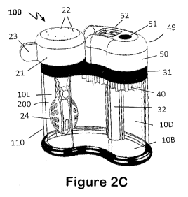
second concern. Secondly, hydrogen peroxide systems are not storage solutions.
Following neutralization, hydrogen peroxide solution becomes water (and 02
which
leaves the cup through little holes in the cap). Water typically fails to
provide contact
lenses with adequate protection from contamination when stored for periods of
time.
Lenses should generally be removed from the neutralized solution and worn
relatively
soon thereafter. Long delays in removing the lenses from the cup, which now
contains
unprotected water, may cause re-contamination of the lenses with opportunistic
microbes. In contrast, a MPDS solution can act as a good storage solution but
typically
contains less disinfecting power against certain fungi and especially fungi
cysts.
[0005] There are two commonly available H202 systems: the one-step H202
system and the two-step H202 system. In the one-step H202 system, the
neutralizing
catalyst neutralizes the hydrogen peroxide solution from the start of the
process, while
in the two-step H202 system, the neutralizing catalyst is added at the end of
the
disinfection phase. While the two-step H202 systems were shown to be more
effective
disinfecting solutions than the MPDS and the one-step H202 systems, two-step
systems
tend to fall out of favor mainly due to the need for the extra step needed to
neutralize
the H202 solution. Furthermore, conventional two-step systems typically fail
to provide
a safe system to avoid ocular toxicity and recontamination. Although great
strides have
been made in contact lens cleaning systems, considerable shortcomings remain.
)\
CA 02849509 2014-03-20
WO 2013/056165 PCT/US2012/060119
3
BRIEF DESCRIPTION OF THE DRAWINGS
[0006] To provide a more complete understanding of the present disclosure
and
features and advantages thereof, reference is made to the following
description, taken
in conjunction with the accompanying figures, wherein like reference numerals
represent like parts, in which:
[0007] FIGURE 1A is a simplified schematic, tridimensional, general
illustration
showing a lens case commonly used in a one-step H202 system (Prior Art);
[0008] FIGURE 1B is a simplified schematic, tridimensional, general
illustration
showing a lens case commonly used either in a one-step H202 system or in a two-
step
H202 system (Prior Art);
[0009] FIGURES 2A through 2D are simplified schematic, tridimensional
illustrations showing some elements and possible example details and potential
operation in accordance with one or more embodiments of the present
disclosure;
[0010] FIGURES 3A and 3B are simplified schematic, tridimensional
illustrations
showing specific parts, elements and possible example details and potential
operation
in accordance with one or more embodiments of the present disclosure;
[0011] FIGURES 4A and 4B are simplified schematic, tridimensional
illustrations
showing other specific parts, elements and possible example details and
potential
operation in accordance with one or more embodiments of the present
disclosure;
[0012] FIGURES 5A and 5B are simplified schematic, tridimensional
illustrations
showing other specific parts, elements and possible example details and
potential
operation in accordance with one or more embodiments of the present
disclosure;
[0013] FIGURE 6 is a simplified schematic, tridimensional illustration
further
showing specific parts, some elements and possible example details and
potential
operation in accordance with one or more embodiments of the present
disclosure;
[0014] FIGURES 7A through 7J are simplified schematic, tridimensional
illustrations showing elements, specific parts and possible example details
and potential
operation in accordance with one or more embodiments of the present
disclosure;
[0015] FIGURES 8A and 8B are simplified schematic, tridimensional
illustrations
showing specific parts, elements and possible example details and potential
operation
in accordance with one or more embodiments of the present disclosure;
CA 02849509 2014-03-20
WO 2013/056165 PCT/US2012/060119
4
[0016] FIGURES 9A and 9B are simplified schematic, tridimensional
illustrations
showing other specific parts, elements and possible example details and
potential
operation in accordance with one or more embodiments of the present
disclosure;
[0017] FIGURES 10A through 10D are simplified schematic, tridimensional
illustrations showing elements, specific parts and possible example details
and potential
operation in accordance with one or more embodiments of the present
disclosure;
[0018] FIGURES 11A through 11H are simplified schematic, tridimensional
illustrations showing elements, specific parts and possible example details
and potential
operation in accordance with one or more embodiments of the present
disclosure; and
[0019] FIGURES 12A through 12D are simplified schematic, tridimensional
illustrations showing elements, specific parts and possible example details
and potential
operation in accordance with one or more embodiments of the present
disclosure.
CA 02849509 2014-03-20
WO 2013/056165 PCT/US2012/060119
DETAILED DESCRIPTION OF EXAMPLE EMBODIMENTS
OVERVIEW
[0020] An apparatus for use with contact lenses is provided in one
example and
includes a contact lens cleaning system for cleaning and disinfecting contact
lenses,
wherein the contact lens cleaning system contains a reservoir, a lens holder
assembly,
and one or more mechanisms associated with the operation of the contact lens
cleaning
system. In more particular instances, the contact lens cleaning system can
have a
physical shape which is both secured and ergonomic.
[0021] In other implementation, the contact lens cleaning system can have
a
general kidney-like structure. In other examples, the contact lens cleaning
system can
have a general round or oval structure.
[0022] In more particular instances, the contact lens cleaning system can
have
elements associated with user's compliance. In other instances, the contact
lens
cleaning system can have elements associated with user's safety.
[0023] Additionally, the contact lens cleaning system can have a locking
system
configured to selectively prevent the lens holder assembly from being removed
from the
reservoir during an unsafe condition. The locking system is driven by a drive
mechanism and may be either a mechanical type system or an electrical type
system.
In some instances, the locking system may be overridden by a user during the
cleaning
or storage process.
[0024] Furthermore, the drive system of the contact lens cleaning system
controls
the automated features of the cleaning system and storage systems, such as a
user
interface, a catalyst, and a concentrate dispensing system. The drive system
selectively delivers and removes a catalyst from the cleaning solution. The
user
interface provides user feedback regarding the phases of operation of the
cleaning
system. In other instances, the drive system regulates a concentrate
dispensing system
to permit the safe storage of the contact lenses. The concentrate dispensing
system
may use an internal reservoir for holding concentrated storage solution or an
external
reservoir holding both cleaning solution and concentrate storage solution.
CA 02849509 2014-03-20
WO 2013/056165 PCT/US2012/060119
6
[0025] To use the cleaning system, contact lenses are inserted into a
lens holder
assembly which is then coupled to a complex base. The complex base surrounds
and
seals a reservoir to ensure a hermetically closed reservoir environment. The
complex
base has at least two segments. The lens holder is located within a first
segment. The
reservoir is filled and a catalyst is introduced into the cleaning solution.
The catalyst
enters the cleaning solution from a second segment of the complex base.
[0026] In some instances, the method may include locking the lens holder
assembly to prevent removal of the contact lenses during an unsafe condition.
The
locking system may also be a mechanical type system or an electrical type
system. In
selected instances, the locking system may be overridden by a user.
[0027] Additionally, the method may include activating a drive mechanism
to
activate and selectively control the cleaning system. The drive mechanism may
automatically fill the reservoir with cleaning solution and control the
movement of the
catalyst.
[0028] A user may receive user feedback regarding the phases of operation
of
the cleaning system and/or storage system through a user interface. The user
interface
may include digital displays and lighting representing selected information.
[0029] In other instances, the method can include injecting a
concentrated
storage solution into a neutralized cleaning solution to avoid recontamination
of the
lenses during storage. Doing so permits the lenses to be stored in a safe
environment.
[0030] Furthermore, other instances of the method may include coating
components of the cleaning system with antibacterial agents to prevent
microbial growth
on selected surfaces of the cleaning system.
CA 02849509 2014-03-20
WO 2013/056165 PCT/US2012/060119
7
EXAMPLE EMBODIMENTS
[0031] Turning to FIGURE 1A, FIGURE 1A is a simplified, schematic
tridimensional illustration of a common contact lens case 210 for cleaning
contact
lenses. Contact lens case 210 is representative of the one-step hydrogen
peroxide
systems where contact lens disinfection and hydrogen peroxide neutralization
occur
simultaneously. Contact lens case 210 includes a cup 16 and a lens holder
assembly
302. Lens holder assembly 302 includes a cap 14, lens basket system 18, and a
neutralizer ¨ a platinum-coated disc 8 ¨ at its distal end. In operation,
contact lenses are
placed in lens basket system 18 and cup 16 is filled with 3% hydrogen peroxide
solution
up to line 6, which is marked on the cup wall. Lens holder assembly 302 is
then
immersed in the hydrogen peroxide solution within cup 16, and cap 14 is
closed.
Disinfection of contact lenses by the hydrogen peroxide solution then takes
place
simultaneously with the break-down (neutralization) of the same hydrogen
peroxide
solution, catalyzed by the platinum-coated disc 8, into water and oxygen; the
later
escapes the system through holes 12 on top of cap 14.
[0032] FIGURE 1B is a simplified, schematic tridimensional illustration
of another
common contact lens case 230 for cleaning contact lenses. Contact lens case
230
includes a cup 16 and a lens holder assembly 304. Lens holder assembly 304
includes
a cap 14 and a lens basket system 18. In operation, contact lenses are placed
in lens
basket system 18 and cup 16 is filled with 3% hydrogen peroxide solution up to
line 6,
which is marked on the cup wall. A tablet, containing the enzyme catalase, is
then
thrown into the hydrogen peroxide solution followed by immersing lens holder
assembly
304 in the hydrogen peroxide solution within cup 16 and closing cap 14. Here,
again,
disinfection of contact lenses by the hydrogen peroxide solution occurs
simultaneously
with the break-down (neutralization) of the same hydrogen peroxide solution,
catalyzed
by the enzyme catalase, into water and oxygen; the later escapes the system
through
holes 12 on top of cap 14.
[0033] Common contact lens case 230 can, however, be part of a two-step
hydrogen peroxide system simply by delaying the introduction of the tablet
containing
catalase after contact lens disinfection is complete. The two-step system thus
described
CA 02849509 2014-03-20
WO 2013/056165 PCT/US2012/060119
8
allows for a full disinfection phase to take place following with a separate
neutralization
phase, where hydrogen peroxide is broken down into water and oxygen.
[0034] Consequently, the two-step hydrogen peroxide systems are shown to
be
very efficient disinfecting solutions; for example, by killing large inocula
of
Acanthamoeba cysts ¨ the resistant form of this amoeba. The one-step hydrogen
peroxide systems, on the other hand, are less effective than the two-step
hydrogen
peroxide systems and their disinfecting action was compared to that of the
common
multi-purpose disinfecting solution.
[0035] From the data available and from an antimicrobial disinfection
perspective,
it is concluded that use of two-step H202 solutions should be the solution of
choice.
[0036] Disadvantages of use of the two-step hydrogen peroxide system may
include (a) wearer's either inadvertent failure to neutralize the hydrogen
peroxide
solution or premature removal of lenses from the system, thus suffering pain
and
trauma associated with putting hydrogen peroxide into the eyes, (b) wearer's
use of
hydrogen peroxide solution as it were multi-purpose solution for cleaning and
rinsing of
contact lenses, and (c) the extra procedure needed to be performed by the
wearer
when using the two-step hydrogen peroxide, which probably make these solutions
fall
out of favor.
[0037] Given the above, there is a need for a system that encourages
contact
lens wearers to use the effective two-step hydrogen peroxide system while
addressing
its disadvantages. Hence, the objective of this disclosure to provide such a
solution by
presenting a contact lens cleaning system, which functions as a two-step
hydrogen
peroxide system while, for the user, it functions as a one-step system.
[0038] In general, embodiments of the present disclosure present a system
for
the disinfection and/or cleaning of contact lenses. The contact lens cleaning
system can
comprise a reservoir, a complex base, moving components, one or more
mechanical or
electro-mechanical mechanisms, a cap and a lens holder assembly.
[0039] Turning to FIGURES 2A through 2D, FIGURES 2A-2D are simplified
schematic, tridimensional illustrations showing one embodiment of cleaning
system 100.
Cleaning system 100 includes at least: a reservoir 110, a lens holder assembly
200, a
controller/timer trigger motor 60, and a user interface 71. The following
figures disclose
CA 02849509 2014-03-20
WO 2013/056165 PCT/US2012/060119
9
a plurality of embodiments and features associated with various cleaning
systems of the
present application. It is understood that any of the features disclosed in
the present
application may be utilized and incorporated into any cleaning system
embodiment
disclosed herein.
[0040] Contact lens cleaning system 100 may be made from compatible
plastic
materials, generally kidney shaped or oval shaped apparatus designed to be
ergonomic
and have good physical stability. Contact lens cleaning system 100 has a
reservoir 110
(FIGURES 2A and 2B) having substantially a shape suitable for containing the
disinfecting solution, part of the moving components, and the lens holder
assembly 200
(FIGURES 20 and 2D). Reservoir 110 substantially has a base 10B, at its
bottom, and
a top circumferential strip area, which fits encircling wall 31 of complex
base 120
(FIGURES 3A and 3B). While a one entity, reservoir 110 is generally divided
into a lens
side 10L, to accommodate the lens holder assembly 200 (FIGURE 6), and a disc
side
10D, to accommodate drive means 48 the vertical shaft 32 (FIGURE 3C) and the
moving platinum-coated disc 40 (FIGURES 2C and 2D). Reservoir 110 may be
opaque
or transparent and may be constructed from a material which is substantially
compatible
with the disinfecting solution and contact lens materials.
[0041] Complex base 120 (FIGURES 3A and 3B) has substantially an
encircling
wall 31, a cylindrical opening 20, and a raised area 31F. Encircling wall 31,
having
identical circumferential shape to that of reservoir 110, matches and is
attached to the
top circumferential strip area of reservoir 110 by means of, including but not
limited to,
glue, heat or a combination thereof, to insure a hermetically closed reservoir
environment. Complex base 120 (FIGURE 3A) may be generally divided into 3
segments: lens segment 120L, which is vertically aligned with the lens side
10L of
reservoir 110 (FIGURE 2A); disc segment 120D, which is vertically aligned with
disc
side 10D of the reservoir 110 (FIGURE 2A); and bridge segment 120Br, which
connects
lens segment 120L with disc segment 120D. Lens segment 120L is substantially
made
of a short, vertical, open cylinder 20 (FIGURES 3A and 3B) having top and
bottom
ends. While the bottom end opens into the bottom surface of complex base 120
(31R,
FIGURE 3B), the top end is equipped with a fitting means, including but not
limited to, a
thread designed to fit and quickly (turning the cap only a quarter circle)
lock cap 21 of
CA 02849509 2014-03-20
WO 2013/056165 PCT/US2012/060119
lens holder assembly 200 (FIGURES 2A-2D, 4B, 6, 7A-7C, 9A-9B, 10A-10D, and 11A-
1 1 F) in place. The top part of disc segment 120D of complex base 120 (FIGURE
3A) is
substantially composed of a raised surface 31F, serving as the floor of a
mechanism
chamber 49, which is designed to precisely mate the encircling wall of cover
50 of the
mechanism chamber 49 (FIGURE 2A-2D). Encircling wall of cover 50 and the side
area
of floor 31F (FIGURE 3A and 3B) of the mechanism chamber 49 are attached by
means
of, including but not limited to, glue, heat, or a combination thereof to
insure a
hermetically closed mechanism chamber.
[0042] Floor 31F of the mechanism chamber 49 (FIGURE 3A) has a few
depressions and holes to allow for the housing and operation various
components. A
drive mechanism 67 is configured to control the cleaning process and storage
process
of the cleaning systems of the present application. In doing so, drive
mechanism 67
controls the automated activities within the cleaning and storage systems.
Motor 60, as
well as systems 60A and 60B described later, are types of drive mechanisms 67.
Floor
31F has substantially a motor depression 60x to accommodate motor 60 and motor
gear 80H (FIGURE 2D and 4B), a battery depression 70x to accommodate battery
70
(FIGURE 2D and 4B), a vertical gear depression 80Vx to accommodate vertical
gear
80V (FIGURES 4A and 4B), and a uni- or bi-winged hole 32L leading downward
into a
lumen within vertical shaft 32 to accommodate vertical spiral shaft drive 90
and
accompanying magnet body 45 (FIGURE 8A). The bottom part of disc segment 120D
of
complex base 120 (FIGURE 3B) exhibits the encircling wall 31, the base recess
area
31R, and the exterior of the hollow vertical shaft 32 with its lateral wings
32W.
[0043] As shown in FIGURES 4A and 8A, in one or more embodiments of the
present disclosure, magnet body 45 substantially has a cylindrical shape,
inner spiral
threads 46, which fit external spiral threads 92 of spiral shaft drive 90
(FIGURE 4A), and
lateral projections 47, which are designed to fit and run along the lumen of
wings 32W
of vertical shaft 32 (FIGURES 3A and 3B). Iron-embedded, platinum-coated disc
40
(FIGURE 4A and 4B) is designed to travel along external surface of vertical
shaft 32 by
being magnetically attracted, through the wall of vertical shaft 32, to magnet
body 45,
which travels inside the lumen of vertical shaft 32 along spiral shaft drive
90 rotation of
which driven by motor 60.
CA 02849509 2014-03-20
WO 2013/056165 PCT/US2012/060119
11
[0044] Iron-embedded, platinum-coated disc 40 (FIGURES 4A and 4B) is
substantially made of compatible materials, including but not limited to,
plastic, in any
tridimensional shape and form, which would increase its surface area. Disc 40
substantially has a central uni- or bi-winged throughout hole designed to
accommodate
and slide on a uni- or bi-winged external surface of vertical shaft 32
(FIGURES 4B).
Also, disc 40 may have one or more additional holes designed to adjust the
disc weight
for proper movement along the exterior surface of vertical shaft 32 and
increase surface
area. Circular or semi-circular metal sheets 43 made of, including but not
limited to iron,
are embedded in the plastic of disc 40 in proximity of the central uni- or bi-
winged hole
such that they can be magnetically attracted by the moving magnet body 45
along
vertical spiral shaft drive 90 (FIGURE 8A) and move disc 40 down (FIGURE 2D)
and up
(FIGURE 20) the external surface of vertical shaft 32 at start and end of
neutralization
phase, respectively. For clarification: the terms 'iron-embedded' and
'platinum-coated'
are used here and throughout this document only for convenience and do not
imply any
restriction to the sole use of these materials. Any magnetically attractable
material may
replace iron and any transition metal or any other agent, capable of
catalyzing the
neutralization of hydrogen peroxide, may replace platinum. Also, while
throughout this
disclosure the magnet entity is described as a cylindrical body traveling
inside the lumen
of vertical shaft 32 and metal sheets are embedded within the plastic disc,
this is not to
limit the vice versa situation, where magnet sheets are embedded within the
plastic disc
and the cylindrical body traveling along the lumen of vertical shaft 32 is
made of one or
more magnetically attractable metals or other materials.
[0045] FIGURES 2A, 2B, 5A, 5B, and 11A show some potential details of
mechanism cover 50 of contact lens cleaning system 100 of one or more
embodiments
of the present disclosure. Cover 50 may be either transparent or opaque and
may have
substantially any desired shape. In general, cover 50 is equipped with a user
interface
71 with depressions, excavations and holes to accommodate components of the
mechanism, display, and control. User interface is configured to provide user
feedback
regarding the phases of operation of the contact lens cleaning system, as well
as
activate the cleaning system as described in any of the embodiments of the
present
application. Top area 50T of cover 50 (FIGURE 5A), for instance, may
substantially
CA 02849509 2014-03-20
WO 2013/056165 PCT/US2012/060119
12
have excavation 51x for the ON/OFF rubber button 51 (FIGURE 2C), an excavation
52x
for LCD display 52 (FIGURE 2C), an excavation 53x for LCD screen 53 (FIGURE
2C),
and holes in these excavations. Holes (FIGURES 5A and 5B) may include a rubber
button hole, within excavation 51x, to accommodate the lower projection of
rubber
button 51 and wiring thereof; one or more connector holes, within excavation
52x, to
connect LCD display 52 with an underlined circuit board (not shown); and holes
within
excavation 53x, for one or more LED indicators, to accommodate the LEDs
themselves
and their wiring connections with an underling circuit board. Cavity 50C,
delineated by
wall 54, of cover 50 (FIGURE 5B) may substantially be provided with elements
that
support and/or fix in place components of the mechanism chamber. One such
element
is the motor support projection pair 60S (FIGURE 5B) that substantially hold
the body of
motor 60 (FIGURE 4B) in place. Also, accommodated within cavity 500, and may
substantially be attached to the inner top surface of cover 50, is the
mechanism's circuit
board and wiring thereof (not shown), designed to control the overall
automated
operation of the contact lens container. For clarification, location of
elements which may
control one or more functions of the contact lens cleaning system of the
present
disclosure is not limited to the mechanism chamber. They me be found, in one
or more
embodiments of the present disclosure, anywhere in the contact lens cleaning
system.
For instance, in a special recess or cavity at the bottom of the contact lens
cleaning
system as depicted in FIGURE 10C and 10D, where printed circuit board 96 and
controller 56 are located in an inclusion on the bottom of reservoir 110 along
with
batteries 58.
[0046] In one or more embodiments of the present disclosure, the contact
lens
cleaning system may include different shapes of LCD 52 (FIGURES 2A and 2B) and
one or more LED lights (FIGURES 20 and 5A). These LCDs and LEDs may provide
information about time, status of the various phases of operation of the
contact lens
cleaning system (e.g., disinfection, neutralization, completion, and storage
status) and
information, which may be related to user's safety or function of the contact
lens
cleaning system.
[0047] Many designs of lens holder assembly 200 and cap 21 (FIGURE 6) may
be incorporated in one or more embodiments of the present disclosure. Contact
lens
CA 02849509 2014-03-20
WO 2013/056165 PCT/US2012/060119
13
cleaning system 100 (FIGURES 2A) for instance, presents cap 21 as having a
rough
circumferential surface to hold on while closing or opening the cap. This cap
may have
one or more simple or tortuous holes 22 for the escape of oxygen produced
during
neutralization of hydrogen peroxide solution. Also, cap 21 may have one or
more
locking or latching systems 81, including but not limited to, mechanical types
such as a
serrated circumferential area 34 (FIGURES 2B, 7A-7E, 9A, 9B, and 10A-10D) and
electrical types such as the cap electric latch 94 depicted in FIGURES 10A-10D
for one
embodiment 500 of the present disclosure. Locking systems 81 are configured to
selectively prevent removal of lens holder assembly 200 from reservoir during
any
unsafe condition. An unsafe condition refers to periods of time where either
the lenses
are contaminated or potentially contaminated (after neutralization as a result
of storage)
or the cleaning solution has not been sufficiently neutralized, thereby
preventing a user
from inserting hydrogen peroxide solution into the eye. In another embodiment
with cap
21, cap 21 may present a thumb tab 23 (FIGURES 2C, 2D, and 6) for an easier
cap
operation. Inner threads of cap 21 and outer threads of cylinder 20 (FIGURE
3A) along
with cap locking systems 81 including, but not limited to, cap locking
mechanisms 34
(FIGURES 9A and 9B) and 94 (FIGURES 10A and 10B) and other mechanical or
electrical features are designed to provide a quick, quarter circle cap
locking/unlocking
operation.
[0048] FIGURE 6 is a simplified schematic, tridimensional illustration
showing
specific parts, some elements and possible example details and potential
operation of
lens holder assembly 200 in accordance with one or more embodiments of the
present
disclosure. Lens holder assembly 200 is configured to locate and releasably
secure
lenses within reservoir 110. Lens holder assembly 200 is composed of cap 21
with
holes 22, for the release of oxygen gas generated during the neutralization of
hydrogen
peroxide, on its top area; and thumb tab 23 to open and close the cap onto
opening 20
of lens segment 120L of complex base 120 (FIGURE 3A). Central shaft 26,
originating
from or attached to the inner surface of cap 21 (FIGURE 6) ends distally with
a
fenestrated, bi-convex lens support body 24S having groove 27, which is
adapted to
lock in the right 24R and left 24L lens baskets 24 via their respective, 28R
and 28L,
CA 02849509 2014-03-20
WO 2013/056165 PCT/US2012/060119
14
locking elements. Shaft 26 is equipped with a transverse rod 25, which serves
as a
hinge for lens baskets 24R and 24L.
[0049] Below is a description of a potential operation of the contact
lens cleaning
system. It is provided here for illustration purposes only and, in no way,
limits any of the
scopes of operation of any of the embodiments of the present disclosure.
[0050] Pre-operation, right and left contact lenses are placed on lens
support
body 24S (FIGURE 6) under baskets 24R and 24L, respectively, which are then
closed
and locked on locking groove 27. Reservoir 110 (FIGURE 2C) is then filled with
hydrogen peroxide solution up to a marked line, which is way below the bottom
surface
of the iron-embedded, platinum disc 40, which is in the up position, within
base recess
31R (FIGURE 3B). The lens-containing lens holder assembly 200 is then entered,
through opening 20 of the complex base 120 (FIGURE 3A), and immersed in the
hydrogen peroxide solution at the lens side 10L of reservoir 110. Thumb tab 23
is then
turned 90 degrees laterally ¨ from the front, unlocked position ¨ to lock cap
21. This
contact lens cleaning system status is depicted in FIGURE 20.
[0051] Then a user activates motor 60 through user interface 71 to
activate the
contact lens cleaning system, including but not limited to, activating a
controller, timer
and LCD display, and turn on disinfection LED light 52. After a predetermined
disinfection time [end of disinfection phase], the controller/timer trigger
motor 60 to
rotate its motor bevel gear 80H, which in turn engages and rotates vertical
bevel gear
80V (FIGURE 4B) and spiral shaft drive 90 (FIGURE 4A). Male spiral threads 92
on
spiral shaft drive 90 and female spiral threads 46 on the inner surface magnet
body 45
(FIGURES 8A and 2D), along with magnet body lateral projections 47, move
magnet
body 45 and the magnetically attracted iron-embedded, platinum-coated disc 40
downward into the hydrogen peroxide solution [beginning of neutralization
phase]
(FIGURE 2D). LED light indicating neutralization 52 is turned on. After a
predetermined
neutralization time [end of neutralization phase], the controller/timer
trigger motor 60 to
counter-rotate and pull disc 40 out of the neutralized solution, which is now
substantially
composed of water. At this point, the user may turn the thumb tab 90 degrees
medially
to the front side, to unlock cap 21, and open the basket cage to remove the
clean
contact lenses. If not removed within a predetermined time, the dedicated LED
light will
CA 02849509 2014-03-20
WO 2013/056165 PCT/US2012/060119
flash to alert the user to remove the lenses and either wear them or store
them in a
storage solution.
[0052] FIGURES 9A and 9B are simplified schematic, tridimensional
illustrations
showing another possible set of details and potential operation associated
with locking
and unlocking or cap 21 in one or more embodiments of the present disclosure.
FIGURE 9A shows contact lens assembly 200 with cap 21 and its serrated area
34.
Upon 90 degree closure of cap 21, the cap 21 engages a locking system 81
composed
of cap lock pivot arm 68 and cap lock slide 66 to prevent the user from
inadvertent
opening cap 21 prior to full neutralization (locked, FIGURE 9B). In this
embodiment,
magnet body 45 possesses a vertical projection 48, which is an extension of
one of its
lateral projections. Post neutralization, iron-embedded, platinum-coated disc
40 raises
to its up position in base recess 31R along with magnet body 45. At this
point, magnet
vertical projection 48 pushes cap lock pivot arm 68 upward to disengage cap
lock slide
66 from the cap serrated area 34, thus unlocking cap 21 for the user to remove
the
contact lenses from the neutralized solution (unlocked, FIGURE 9A).
[0053] FIGURES 7A-7J are simplified schematic, tridimensional
illustrations
showing yet another possible set of details and potential operation associated
with one
or more embodiments of the present disclosure. FIGURES 7A-7J include contact
lens
cleaning system 300. Contact lens cleaning system 300 has many of the features
of
contact lens cleaning system 100. In addition, contact lens cleaning system
300 is
equipped with one or more mechanisms designed to convert the neutralized
hydrogen
peroxide solution (basically, water) into a storage solution. The features
specific for
conversion of the resultant water into an effective storage solution are
easily seen in
FIGURES 7D-7F. FIGURE 7D shows contact lens cleaning system 300 after removing
reservoir 110, cover 50, and complex base 120 to expose details specific to
this
embodiment. Recalling, at the end of neutralization, the user needs to remove
the
lenses from neutralized solution (water) and wear or store them in a storage
solution. In
practice, if the user does not wear his/her contact lenses after they have
been cleaned
with a hydrogen peroxide solution, he/she is likely to leave them in the
water. The
unprotected water has been shown to contaminate with time, thus endangering
the eyes
of the unsuspecting lens wearer.
CA 02849509 2014-03-20
WO 2013/056165 PCT/US2012/060119
16
[0054] FIGURES 7A-7J show a possible set of details and potential
operation,
which is aimed at preventing such ocular complication. Turning to FIGURE 7D,
FIGURE
7D shows a internal reservoir 150 containing concentrated multi-purpose
disinfecting
solution and a concentrate dispensing system 101 composed of a bellows 84, a
connecting, long pipe 88, and a concentrate dispense bellows cylinder gear 82.
Concentrate dispensing system is configured to create a suitable storage
environment
for the lenses following neutralization of the cleaning solution. In
operation, motor 72
drives motor gear 74 to turn elongated intermediate gear 76 which, in turn,
rotates a
bellows lifting drive gear 78 to initially lower and raise the iron-embedded,
platinum-
coated disc 40 according to previously described magnetic operation. At the
end of
neutralization, when disc 40 is in the up position in base recess 31R, bellows
lifting drive
gear 78 (FIGURE 7E) is pushed up to engage concentrate dispense bellows
cylinder
gear 82, and cap 21 is unlocked. A mechanism dedicated to detecting the
vertical
position of the cap, mediated by, but not limited to, LED beam informs the
contact lens
cleaning system controller about the status of cap 21. If cap is not lifted
after a certain
predetermined time, motor 72 actuates the gear chain system (FIGURE 7E) to
rotate
bellows gear 82 to squeeze bellows 84, suck a small volume of concentrated
multi-
purpose solution from internal reservoir 150 through pipe 88, and squirt it
through is
check valve dispense outlet 86 into the resultant water, thus converting it to
an
acceptable, protecting, multi-purpose disinfecting solution, suitable of long
term storage
of contact lenses.
[0055] FIGURES 8A and 8B are simplified schematic, tridimensional
illustrations
showing yet another possible set of details and potential operation associated
with one
or more embodiments of the present disclosure. FIGURES 8A and 8B include
elements
specific for contact lens cleaning system 400. These elements comprise a
vertical shaft
gear 62 and a coupling gear and motor system 64 aimed at rotating vertical
spiral shaft
90 and driving magnet body 45 and it accompanying disc 40 down or up.
[0056] FIGURES 10A through 10D are simplified schematic, tridimensional
illustrations showing elements, specific parts and possible example details
and potential
operation in accordance with one or more embodiments of the present
disclosure.
FIGURES 10A through 10D demonstrate the potential use of external source of
CA 02849509 2014-03-20
WO 2013/056165 PCT/US2012/060119
17
concentrated multi-purpose solution to convert the post-neutralization
resultant water
into an acceptable, protecting, storage solution. Also, one or more embodiment
of the
present disclosure provides a contact lens cleaning solution, which has the
potential to
avoid, or at least, reduce the inadvertent use of hydrogen peroxide solutions
for rinsing
contact lenses and injuring one's eyes. Turning to FIGURES 10A and 10B, FIGURE
10A shows contact lens cleaning system 500 similar in shape and function to
previously
described systems in this document and a sealed, bi-compartmental
bottle/canister 520
containing hydrogen peroxide in one compartment 162 and concentrated multi-
purpose
disinfecting solution in another compartment 164. Contact lens cleaning system
500
comprises a motor 72 and a set of gears similar to another embodiment of the
present
disclosure, which are aimed to lower and raise iron-embedded, platinum-coated
disc 40.
In Also, contact lens cleaning system 500 possesses a pair of electrical
shuttered
nozzles 140, designed to couple with the bottle's pair of one-way valves 160.
In
operation, lenses are placed in lens holder assembly, and cap 21 is
closed/locked in
place. Contact lens cleaning system 500 is then connected to sealed bottle 520
via
nozzles 140 and valves 160. Once the ON button 51 is pressed, a precise volume
of
hydrogen peroxide solution moves from compartment 162 to contact lens cleaning
system 500, through the respective nozzle and valve. After a predetermined
time
following neutralization, if cap 21 has not been lifted, the other shutter 160
of bottle 520
is open to deliver a predetermined small volume of concentrated multi-purpose
solution
to convert the resultant water into a protective storage solution.
[0057] FIGURES 11A through 11H are simplified schematic, tridimensional
illustrations showing elements, specific parts and possible example details
and potential
operation in accordance with one or more embodiments of the present
disclosure.
FIGURES 11A through 11H show contact lens cleaning system 600. Contact lens
cleaning system 600 is mechanically operated and uses catalase tablets as
neutralizing
agents. FIGURES 11A through 11H illustrate motor 60A, which is another
embodiment
of delivering a catalyst to the hydrogen peroxide solution compared to motor
60
described previously. FIGURE 11D shows contact lens cleaning system 600
following
removal of cover 50 and reservoir 110 to expose the underlying structures of
the
system. Features specific to contact lens cleaning system 600 include a spring
112-
CA 02849509 2014-03-20
WO 2013/056165 PCT/US2012/060119
18
actuated, tablet-loaded pill helix magazine 108, pill revolver 104 (FIGURE
11H), spring-
actuated timer and associated gear 116 (FIGURE 11E) and a complex pill slide
117. In
operation, timer spring is charged by action of pill revolver 104 gear on
timer's gear 116
following movement of handle 106 of pill revolver in one direction. After a
predetermined
time [post-disinfection], the hole of the pill revolver 104 coincides with the
proximal,
internal opening 119 of the helix system and opening of the pill slide outlet
118 to allow
a the spring-pushed tablet to leave the helix magazine 108 and drop, via pill
slide 117
and pill slide outlet 118, into the sealed contact lens side of reservoir 110
to initiate
neutralization.
[0058] FIGURES 12A through 12D are simplified schematic, tridimensional
illustrations showing elements, specific parts and possible example details
and potential
operation in accordance with one or more embodiments of the present
disclosure.
FIGURES 12A through 12D show contact lens cleaning system 700. Contact lens
cleaning system 700 comprises reservoir 110 having two separate compartments:
a
lens assembly compartment 156 and a tablet-feed compartment 154. Cleaning
system
700 includes motor 60B which is another embodiment of motor 60A and 60 used to
deliver a catalyst to the hydrogen peroxide solution. The walls compartment
154 are
equipped with a built-in tablet-strip track 132 having an external, feeding
end 134 and
an internal, loading end 136. Hydrogen peroxide neutralization occurs by use
of
catalase-containing tablets. In operation, strips of aluminum-packaged
catalase tablets
are fed into track 132 through external feed 134. Post-disinfection, a time-
dependent,
spring actuated grip-punch assembly 146, by turning handle 144, rotates to
grip and
advance the tablet-strip along track 132 in front of loading end 136 where a
tablet punch
168 to press on the aluminum blister to release the catalase tablet through
the pill feed
182 into lens compartment 156 through pill outlet 184.
[0059] In one or more embodiments of the present disclosure, the contact
lens
cleaning systems may have a magnet body that is connected to a flexible,
serrated belt,
which engages with a motor drive gear. In operation, the motor drive gear
rotates to
drive the serrated belt down the lumen of the vertical shaft to start
neutralization or up at
the end of neutralization.
CA 02849509 2014-03-20
WO 2013/056165 PCT/US2012/060119
19
[0060] In another embodiments, the solid magnet body may be attached to
the
distal end of a flexible, yet strong, thin strip or string, which is
connected, at its proximal
end, to a horizontal motor shaft. At pre-operation and disinfection phases,
the strip is
coiled/rolled on the motor shaft and the disc is in its up position. Rotation
of the motor
shaft in one direction uncoils/unrolls the strip or string to push the magnet
body
downward along the lumen of the vertical shaft, thus downing the iron-
embedded,
platinum-coated disc into the hydrogen peroxide solution to begin
neutralization. At the
end of the neutralization phase, the motor counter-rotates to coil/roll the
strip or string
on its shaft, thus shortening the strip or string, and pulling the magnet body
upward
(inside the lumen of the vertical shaft) and the iron-embedded, platinum-
coated disc
upward (outside the lumen of the vertical shaft) and out of the neutralized
solution.
[0061] Another objective of the present invention is to address the
potential
surface bio-contamination of contact lens containers and concomitant
deposition of
biofilm ¨ a thin layer of microorganisms adhering to the surface together with
the
polymers that they secrete. To this end, components of contact lens container
of all
embodiments of the present invention may be embedded or surface-coated with
effective antibacterial agents so that they can self-decontaminate after a bio-
contamination event ¨ even an unrecognized one.
[0062] Antimicrobials which may be used for said application include, but
are not
limited to, silver, copper, zinc, titanium, silicon, ammonium, aluminum; their
derivatives
and combination thereof. By way of example, one may use the metal silver,
considered
to be the least cytotoxic and most potent agent against bacteria, along with
copper,
which has a strong antifungal effect ¨ creating a synergistic outcome with
respect to
practical effectiveness.
[0063] Although the present disclosure has been described in detail with
reference to particular arrangements and configurations, these example
configurations
and arrangements may be changed significantly without departing from the scope
of the
present disclosure. Moreover, the present disclosure is equally applicable to
various
technologies, aside from those disclosed herein, as these have only been
offered for
purposes of discussion.
CA 02849509 2014-03-20
WO 2013/056165 PCT/US2012/060119
[0064] Numerous other changes, substitutions, variations, alterations,
and
modifications may be ascertained to one skilled in the art and it is intended
that the
present disclosure encompass all such changes, substitutions, variations,
alterations,
and modifications as falling within the scope of the appended claims.