Note: Descriptions are shown in the official language in which they were submitted.
IMPLANTABLE PROSTHESIS FOR REPAIRING OR REINFORCING AN
ANATOMICAL DEFECT
BACKGROUND
Technical Field
[0002] The present disclosure relates to implantable prostheses. More
particularly, the
present disclosure relates to an implantable prosthesis for repairing and/or
reinforcing an
anatomical defect.
Background of Related Art
100031 In the past, in developing spaces and potential spaces within a
body, blunt
dissectors or soft-tipped dissectors have been utilized to create a dissected
space which is parallel
to the plane in which the dissectors are introduced into the body tissue. This
often may be in an
undesired plane, which can lead to bleeding which may obscure the field and
make it difficult to
identify the body structures.
[0004] In utilizing such apparatus and methods, attempts have been made
to develop
anatomic spaces in the anterior, posterior or lateral to the peritoneum. The
same is true for plural
spaces and other anatomic spaces. Procedures that have been performed in such
spaces include
varocele dissection, lymph node dissection, sympathectomy and hernia repair.
In the past, the
inguinal hernia repair has principally been accomplished by the use of an open
procedure which
involves an incision in the groin to expose the defect in the inguinal floor,
remove the hernial sac
CA 2849821 2018-11-08
and subsequently suture the ligaments and fascias together to reinforce the
weakness in the
abdominal wall.
[0005] Recently, laparoscopic hernia repairs have been attempted by
inserting
laparoscopic instruments into the abdominal cavity through the peritoneum and
then placing a
mesh to cover the hernia defect. Hernia repair using this procedure has a
number of
disadvantages, principally because the patch used for hernia repair is in
direct contact with the
structures in the abdominal cavity, as for example the intestines, so that
there is a tendency for
adhesions to form in between these structures. Such a procedure is also
undesirable because
typically the patch is stapled into the peritoneum, which is a very thin
unstable layer covering the
inner abdomen. Thus, the stapled patch can tear away from the peritoneum or
shift its position.
Other laparoscopic approaches involve cutting away the peritoneum and stapling
it closed. This
is time consuming and involves the risk of inadvertent cutting of important
anatomic structures.
[0006] Accordingly, it is an object of the present disclosure to provide
improved
implantable prostheses for repairing and/or reinforcing soft tissue or muscle
wall defects.
SUMMARY
[00071 Accordingly, an implantable prosthesis is provided. The
implantable prosthesis
includes a first biocompatiblc structure, a rigid reinforcement member
positioned adjacent a
bottom side of the first biocompatible structure, a mesh structure positioned
adjacent a bottom
surface of the rigid reinforcement member, a second biocompatible structure
and an anti-
adhesion barrier positioned on a bottom surface of the second biocompatible
structure.
[0008] The first biocompatible structure, in one embodiment, includes at
least
one tether attached thereto. The tether may be a suture-strand tether adapted
to
stabilize and lift the prosthesis against an abdominal wall during surgery.
Additionally, the first biocompatible structure may be
2
CA 2849821 2018-11-08
CA 02849821 2014-03-21
WO 2013/049795 PCT/US2012/058248
configured to receive at least one peripheral fixation. The at least one
peripheral fixation
includes at least one or more of a tack, a suture, and a staple.
[0009] The rigid reinforcement member may be constructed from an absorbable
polymer
material. The rigid reinforcement member may also be configured to have a
plurality of
openings extending therethrough. The rigid reinforcement member further
includes an inner
circumferential ring and a plurality of spoke elements extending thereon. The
rigid
reinforcement member may further include a plurality of guide members molded
thereon. The
rigid reinforcement member is adapted to be partially flexible and
collapsible.
[0010] In one embodiment, a stiffness of the rigid reinforcement member is
greater than a
stiffness of the first and second biocompatible structures.
[0011] In yet another embodiment, a diameter of the second biocompatible
structure is
greater than a diameter of the first biocompatible structure.
[0012] The mesh structure overlaps an inner circumferential ring of the
rigid
reinforcement member. The mesh structure may be constructed to promote tissue
ingrowth.
[0013] In another embodiment, the anti-adhesion barrier may include a
collagen coating.
[0014] In yet another embodiment, an implantable prosthesis is provided.
The
implantable prosthesis includes a first biocompatible structure having a
tether attached thereto
for maintaining stable deployment of the implantable prosthesis through an
abdominal wall; a
rigid reinforcement member positioned adjacent a bottom side of the first
biocompatible
structure, the rigid reinforcement member including an inner circumferential
ring, a plurality of
spoke elements, a plurality of openings, and a plurality of guide members
molded thereon; a
mesh structure positioned adjacent a bottom surface of the rigid reinforcement
member, the mesh
structure overlapping the inner circumferential ring of the rigid
reinforcement member; a second
3
CA 02849821 2014-03-21
WO 2013/049795 PCT/US2012/058248
biocompatible structure and an anti-adhesion barrier having a collagen coating
positioned on a
bottom surface of the second biocompatible structure.
BRIEF DESCRIPTION OF THE DRAWINGS
[0015] The accompanying drawings, which are incorporated in and constitute
a part of
this specification, illustrate embodiments of the disclosure and, together
with a general
description of the disclosure given above, and the detailed description of the
embodiment(s)
given below, serve to explain the principles of the disclosure, wherein:
[0016] FIG. 1 is a high level diagram of the layers of an implantable
prosthesis, in
accordance with the present disclosure;
[0017] FIG. 2 is a cross sectional view of the implantable prosthesis, in
accordance with
the present disclosure;
[0018] FIG. 3 is a top view of the implantable prosthesis, in accordance
with the present
disclosure;
[0019] FIG. 4 is an exploded view of the layers of the implantable
prosthesis, in
accordance with the present disclosure;
[0020] FIGS. 5A-5C illustrate an implantable prosthesis for FIGS. 1-4, and
collapsed
views thereof, in accordance with the present disclosure;
[0021] FIG. 6 is a sagittal view showing the attachment of a mesh structure
to a hernia
sac, in accordance with the present disclosure;
[0022] FIG. 7 is a sagittal view similar to FIG. 6 showing the dissection
of the hernia sac
and the unrolling of the mesh structure, in accordance with the present
disclosure; and
[0023] FIG. 8 is a sagittal view showing the mesh structure in place to
provide the hernia
repair, in accordance with the present disclosure.
4
CA 02849821 2014-03-21
WO 2013/049795 PCT/US2012/058248
DETAILED DESCRIPTION
[0024] Embodiments of the presently disclosed apparatus will now be
described in detail
with reference to the drawings, in which like reference numerals designate
identical or
corresponding elements in each of the several views. As used herein, the term
"distal" refers to
that portion of the tool, or component thereof which is further from the user
while the term
"proximal" refers to that portion of the tool or component thereof which is
closer to the user.
[0025] While the use of the implantable prosthesis is often described
herein as engaging
an incision, it should be recognized that this is merely exemplary and is not
intended to limit the
use of the assembly in any way, but rather it should be recognized that the
present disclosure is
intended to be useable in all instances in situations in which the implantable
prosthesis engages
an incision, a naturally occurring orifice, or any other suitable opening.
[0026] Before explaining the present disclosure in detail, it should be
noted that the
present disclosure is not limited in its application or use to the details of
construction and
arrangement of parts illustrated in the accompanying drawings and description.
The illustrative
embodiments of the present disclosure may be implemented or incorporated in
other
embodiments, variations and modifications, and may be practiced or carried out
in various ways.
For example, although the present disclosure is described in detail as it
relates to implantable
prostheses for repairing umbilical hernias, it is to be understood that such
devices may readily be
used for repairing various other soft tissue or muscle wall defects, including
but not limited to
trocar site punctures, small ventral hernias etc.
[0027] However, for sake of clarity, the present disclosure will be
described relating to
an implantable prosthesis for repairing an anatomical defect, such as a tissue
or muscle wall
hernia, including an umbilical hernia, and for preventing the occurrence of a
hernia at a small
CA 02849821 2014-03-21
WO 2013/049795 PCT/US2012/058248
opening or weakness in a tissue or muscle wall, such as at a puncture tract
opening remaining
after completion of a laparoscopic procedure.
[0028] Surgical meshes of the present disclosure may also include at least
one bioactive
agent. The term "bioactive agent", as used herein, is used in its broadest
sense and includes any
substance or mixture of substances that have clinical use. A bioactive agent
could be any agent
which provides a therapeutic or prophylactic effect, a compound that affects
or participates in
tissue growth, cell growth, cell differentiation, an anti-adhesive compound, a
compound that may
be able to invoke a biological action such as an immune response, or could
play any other role in
one or more biological processes. For example, a surgical mesh may be coated
with an anti-
adhesive to inhibit adhesion of the mesh to tissue and/or with a local
anesthetic for temporary
pain relief during implantation. It is envisioned that the bioactive agent may
be applied to the
surgical mesh in any suitable form of matter, e.g., films, powders, liquids,
gels, combinations
thereof, and the like.
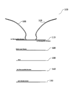
[0029] Referring initially to FIG. 1, layers of an implantable prosthesis
are shown
generally as implantable prosthesis 100. Thus, implantable prosthesis 100 is a
composite
prosthesis constructed from multiple elements as shown in FIGS. 1-4.
[0030] In FIG. 1, the implantable prosthesis 100 includes tethers 105
positioned on a first
biocompatible structure 110. The first biocompatible structure 110 is
positioned on a
reinforcement member 120 positioned on a mesh structure 130. The mesh
structure 130 is
positioned on a second biocompatible structure 140, which in turn is
positioned on an anti-
adhesion barrier 150. In the illustrated embodiments, the first biocompatible
structure 110, the
reinforcement member 120, the mesh structure 130, the second biocompatible
structure 140, and
the anti-adhesion barrier 150 are substantially circular in overall shape,
which is suitable for
6
CA 02849821 2014-03-21
WO 2013/049795 PCT/US2012/058248
repair of typical umbilical hernia defects. Other shapes contemplated may
include, but are not
limited to, oval, square, rectangular, and irregular shapes.
[0031] In one exemplary embodiment, the biocompatible structure 110 is
approximately
a few millimeters to a few inches thick and the second biocompatible structure
140 is
approximately a few millimeters to a few inches thick (see cross-sectional
view 200 of FIG. 2).
The components 105, 110, 120, 130, 140, 150 are aligned as shown in FIGS. 1,
2, and 4, and
then secured together in any suitable manner, such as via bonding by heating
the assembly to a
desired temperature, to form the implantable prosthesis 100.
[0032] The implantable prosthesis 100 includes at least one tether 105 that
extends from
the first biocompatible structure 110 and may be manipulated by a surgeon to
position the
implantable prosthesis 100 relative to the repair site and/or to secure the
implantable prosthesis
100 relative to the opening or weakness in the tissue or muscle wall (see
FIGS. 5A-8). The
tether 105 may be configured to extend through the defect and outside a
patient's body to allow a
surgeon to position and/or manipulate the implantable prosthesis 100 from a
location outside the
body. A portion of the tether 105 may be attached directly to anatomy
surrounding the edges of
the defect opening or to other neighboring tissue, muscle, skin or other
anatomy, using a suture,
staple, tack or other attachment device whether separate from or integrally
formed with the tether
105, so as to anchor the implantable prosthesis 100 in place. Any excess
tether 105 may then be
removed.
[0033] An indicator (not shown) may be arranged on the tether 105 to aid a
surgeon in
determining when the implantable prosthesis 100 has been inserted a sufficient
depth or distance
within a patient. The indicator may be located a desired distance from the
implantable prosthesis
100 such that its location relative to a reference location provides an
indication as to the position
7
CA 02849821 2014-03-21
WO 2013/049795 PCT/US2012/058248
of the implantable prosthesis 100 within the patient without direct
visualization of the
implantable prosthesis 100. The tether 105 may have any suitable width, and
its width may vary
along the length of the tether 105. Multiple tethers 105 may be joined to the
implantable
prosthesis 100 to enhance the positioning and anchoring of the implantable
prosthesis 100.
[0034] The first biocompatible structure 110 may be configured to receive
at least one
peripheral fixation. Such peripheral fixation may be at least one of a tack,
suture or staple.
[0035] The reinforcement member 120 has a substantially similar size and
shape as the
mesh structure 130 (discussed below) and is aligned adjacent a bottom surface
of the first
biocompatible structure 110 (see exploded view 400 of FIG. 4). The
reinforcement member 120
serves to reinforce the implant, and maintain it in a substantially flat
orientation covering the
defect within the patient's body. The reinforcement member 120 is
substantially rigid, yet
flexible enough to allow it to be collapsed for passage through the incision
and defect, but
resilient enough to resume the substantially flat configuration once properly
placed (see FIGS.
5A-8). The reinforcement member 120 may control, in part or in whole, the
direction of strain
when subjected to a radial compressive force. The reinforcement member 120
described herein
has been found particularly suitable for these purposes, and its configuration
greatly improves
resistance to collapsing or buckling of the implant after placement. The
disclosed configuration
provides the additional benefit of controlling the direction of strain of the
implant during
placement.
[0036] The reinforcement member 120 contributes to the stability of the
mesh structure
130, thus allowing it to deploy into and remain in a desired shape. For
example, the
reinforcement member 120 may aid in returning the mesh structure 130 to a
substantially
unfurled or expanded configuration after the folded up or otherwise reduced
implant has been
8
CA 02849821 2014-03-21
WO 2013/049795 PCT/US2012/058248
delivered through the cannula (see FIGS. 5A-8). This stability facilitates
deployment and
placement of the reinforcement member 120 by making it easy to handle. Also,
this stability
minimizes the tendency of the reinforcement member 120 to sag, fold, bend,
collapse, or
otherwise be dislocated. Difficulty in handling, dislocation or bending may
require additional
operative procedures and/or additional anchoring during implantation.
[0037] While the exemplary embodiments illustrate a semi-toroidal shape, it
should be
noted that any symmetrical dimensional form, such as a spherical shape, would
provide the same
functional benefit during installation. As shown in FIGS. 1, 3 and 4, the
reinforcement member
120 has a somewhat toroidal shape, with an optional outer circumferential ring
lying
substantially in a first horizontal plane and an inner circumferential ring
124 lying substantially
in a second horizontal plane (see top view 300 of FIG. 3). Spoke like elements
122 may extend
therebetween. The reinforcement member 120 may be made of, for example, an
absorbable
material, such as polydioxanone, with a thickness of approximately a few
millimeters to a few
inches, which renders its stiffness greater than that of the first or second
biocompatible structures
110, 140.
[0038] In another exemplary embodiment, the reinforcement member 120 may
further
include one or more rib-like elements (not shown) extending longitudinally
along portions of the
spoke-like elements 122. The rib elements may further reinforce and provide
stability to the
implant and prevent permanent inversion of the formed shape from transient
compression
perpendicular to the plane of the center portion of the reinforcement member
120.
[0039] In another exemplary embodiment, the reinforcement member 120 may
further
include a plurality of guide members (not shown) molded thereon. The plurality
of guide
members may aid in the positioning of needles or surgical instruments. Also,
the stiffness of the
9
CA 02849821 2014-03-21
WO 2013/049795 PCT/US2012/058248
reinforcement member 120 may be greater than the stiffness of the first and
second
biocompatible structures 110, 140.
[0040] The mesh structure 130 may be configured to have any suitable shape
or size that
is conducive to facilitating the correction or repair of a particular defect.
The mesh structure 130
described herein has been found particularly suitable for these purposes, and
the illustrated
configuration greatly improves resistance to collapsing or buckling of the
implant after
placement. The illustrated configuration provides the additional benefit of
controlling the
direction of strain of the implant during placement.
[0041] In the exemplary embodiment shown in FIGS. 1-4, the mesh structure
130 has a
relatively flat configuration. However, the mesh structure 130 need not be
flat, and convex,
concave, convex/concave, and more complex shapes also are contemplated. The
mesh structure
130 may be pliable to facilitate manipulation and/or reduction of the
implantable prosthesis 100
during delivery to the defect and/or to conform the implantable prosthesis 100
to the anatomical
site of interest. As illustrated in FIGS. 1-4, the mesh structure 130 has a
generally circular shape.
Examples of other shapes include, but are not limited to, oval, square,
rectangular, and irregular
configurations.
[0042] Additionally, the mesh structure 130 may include one or more layers
of repair
fabric that may promote tissue ingrowth to the mesh structure 130, inhibit
adhesions to the mesh
structure 130, or a combination of both. In one illustrative embodiment, the
mesh structure 130
includes an ingrowth layer (not shown) having a plurality of interstices or
openings which allow
sufficient tissue or muscle ingrowth to integrate the prosthesis with the host
tissue or muscle
after implantation.
CA 02849821 2014-03-21
WO 2013/049795 PCT/US2012/058248
[0043] Moreover, the anti-adhesion barrier 150 provides a bioresorbable
layer that
physically separates and protects the non-absorbable polypropylene mesh
structure 130 and/or
implantable prosthesis 100 from underlying tissue and organ surfaces during
the wound-healing
period to minimize tissue attachment to the polypropylene mesh. The anti-
adhesion barrier 150
may also include a collagen coating.
[0044] In the exemplary embodiments, biocompatible structures 110, 140 may
be
constructed from, at least one of a biodegradable polyglycolic acid, a swine
submucosal
intestine, a collagen, or a polylactic acid. Other suitable suturing (and
band) materials include,
e.g., polymeric materials such as polyethylene teraphthalate (PET), polyester
(e.g., DacronTm),
polypropylene, polyethylene, polycarbonate urethane or metallic material
include, e.g., titanium,
nickel titanium alloy, stainless steel, surgical steels or any combinations
thereof.
[0045] With reference to FIGS. 5A-8, the operation of the implantable
prosthesis 100 is
described.
[0046] In use, the implantable prosthesis 100 may be placed at the defect
site using an
open surgical procedure, by laparoscopically passing the implantable
prosthesis 100 through a
cannula (not shown) that extends along a puncture tract leading to the defect,
such as may be
formed naturally or by a trocar, or through a hybrid procedure where an
incision is formed
through the skin and then a tract is created in the underlying tissue and/or
muscle leading to the
defect site along which the repair device is transported. The implantable
prosthesis 100 may be
flexible, allowing reduction of the implantable prosthesis 100, such as by
folding, rolling or
otherwise collapsing implantable prosthesis 100, into a slender configuration
suitable for
delivery along the puncture tract, or a cannula extending through the puncture
tract, to the defect
site. Upon exiting the puncture tract or cannula, the implantable prosthesis
100 may
11
CA 02849821 2014-03-21
WO 2013/049795 PCT/US2012/058248
automatically unfurl or may be unfolded, unrolled or otherwise deployed by the
surgeon to an
unfurled or expanded configuration suitable to repair the weakness or opening.
[0047] In exemplary embodiment 500, as shown in FIGS. 5A-5C, the
implantable
prosthesis 100 is substantially umbrella shaped, having a central hub 125 with
radially extending
spokes 122. Each of the spokes 122 may be joined to the adjacent spokes 122 by
a mesh
structure 130, forming a radial extension 132 about the central hub 125. The
radial extension
132 has an upper surface 134 and a lower surface 136, where the upper surface
134 contours to
the shape of the inner wall when inserted as shown in FIGS. 6-8, and where the
lower surface
136 contours to the shape of the inner wall when inserted as shown in FIGS. 6-
8. The radial
extension 132 may be substantially circular, elliptical, or rectangular in
plan shape. The spokes
122 are formed from flexible material, allowing the radial extension 132 to be
collapsed for
insertion into an aperture, and then expand conforming to the shape of the
inner wall of the
cavity (see FIGS. 6-8). In the collapsed position, the implantable prosthesis
100 may be
substantially frustoconical or shuttlecock shaped.
[0048] In an alternative embodiment, the radial extension 132 has a greater
thickness at
the central hub 125 edge than at the outside edge.
[0049] Referring to FIGS. 6-8, laparoscopic instruments (not shown) may be
utilized
which are introduced through cannulas (not shown) while visualizing the same
through, for
example, a laparoscope introduced through an introducer device to dissect the
hernia 161 to
permit visualization of its neck 162 as it is entering the internal inguinal
ring 163.
[0050] In use, the roll 156, after it is in the preperitoneal space, is
manipulated so that its
tail 153 is disposed alongside the neck 162 of the hernia sac 161 as shown in
FIGS. 6-8. A
stapling device 166 (see FIG. 6) is then introduced through the cannula to
staple the tail 153 to
12
CA 02849821 2014-03-21
WO 2013/049795 PCT/US2012/058248
the neck 162 by placing staples 167 therein (see FIGS. 7 and 8). These staples
167 serve to
divide the neck of the hernia sac 161 into distal and proximal portions 162a
and 162b. As soon
as this stapling operation is completed, the two portions 162a and 162b are
separated from each
other because of the pressure of the insufflation gas causes the tail 153 of
the mesh structure 130
(see FIGS. 7 and 8) to be pulled upwardly into the inguinal ring to pull with
it the prosthesis 300
(see FIG. 8). The sutures 157 are cut apart to permit the prosthesis 300 to
unroll and to be placed
across the inguinal ring 163 (see FIGS. 6 and 8), which created the main
weakness in the
abdominal wall permitting the hernia which is being repaired to occur. The
proximal portion
162b of the neck 162 is stapled together by staples 173 as shown in FIG. 7.
The proximal
portion 162 is then permitted to fold back into the desired anatomical
location within the
abdomen.
[0051] A tail 153 may be secured to the prosthesis 300 substantially in the
center thereof,
in a suitable manner. For example, as shown, the tail 153 may be provided with
split portions,
which are split apart and offset with respect to each other, which are secured
to an inner
circumferential ring 124 of the reinforcement member 120 (see FIG. 7) and
secured to the first
biocompatible structure 110 by suitable means. The tail 153 may be formed of
the same material
as the first biocompatible structure 110, or it can be formed of a different
material, such as
Goretex0.
[0052] As such, in accordance with FIGS. 6-8, anatomic spaces may be
created in
various parts of the human body, for example in the preperitoneal area to
provide a space
anterior to the peritoneum for hernia repair and for varocelc dissection.
Additionally, the mesh
structure 130, as well as the reinforcement member 120 of the implantable
prosthesis 100 aid in
the creation of a stable, rigid structure appropriate for performing
laparoscopic hernia repair.
13
CA 02849821 2014-03-21
WO 2013/049795 PCT/US2012/058248
[0053] It is understood that there may be a variety of device designs of
mesh structures
130 or reinforcement members 120 or biocompatible structures 110, 140 to
accomplish the
expansion of a device from a first configuration, to a second configuration to
occupy at least a
portion of the sub-annular space and reduce re-extrusion of the nucleus. These
devices may be
constructed of single components or multiple components, with a variety of
different materials,
whether synthetic, naturally occurring, recombinated (genetically engineered)
to achieve various
objectives in the repairing and/or reinforcing of soft tissue or muscle wall
defects.
[0054] Moreover, meshes structures 130, reinforcement members 120, and/or
biocompatible structures 110, 140 may be attached in a number of methods. It
should be
appreciated that the present disclosure is not limited to any particular
attachment method. For
example, the layers (see FIG. 1) may be bonded together by melting the layers
at specific
locations or in a specific pattern; sonic, induction, vibration, or
infrared/laser welding the layers;
or using a suitable bonding agent. The point or points of attachment may
comprise any suitable
pattern, such as a spiral pattern, a serpentine pattern, or a grid-like
pattern of dots or beads, that
maintains a sufficient quantity of open or non-impregnated interstices for
tissue or muscle
infiltration.
[0055] Implantable prostheses of the present disclosure include a first
biocompatible
structure, a rigid reinforcement member positioned adjacent a bottom side of
the first
biocompatible structure, a mesh structure positioned adjacent a bottom surface
of the rigid
reinforcement member, a second biocompatible structure, and an anti-adhesion
barrier positioned
on a bottom surface of the second biocompatible structure.
[0056] In any of the presently disclosed embodiments, the first
biocompatible structure
includes at least one tether attached thereto. In any of the presently
disclosed embodiments, the
14
CA 02849821 2014-03-21
WO 2013/049795 PCT/US2012/058248
tether is a suture-strand tether adapted to stabilize and lift the prosthesis
against an abdominal
wall during surgery. In any of the presently disclosed embodiments, the first
biocompatible
structure is configured to receive at least one peripheral fixation. In any of
the presently
disclosed embodiments, the at least one peripheral fixation includes at least
one or more of a
tack, a suture, and a staple. In any of the presently disclosed embodiments,
the rigid
reinforcement member is constructed from an absorbable polymer material. In
any of the
presently disclosed embodiments, the rigid reinforcement member is configured
to have a
plurality of openings extending therethrough. In any of the presently
disclosed embodiments, the
rigid reinforcement member includes an inner circumferential ring and a
plurality of spoke
elements extending thereon. In any of the presently disclosed embodiments, the
rigid
reinforcement member includes a plurality of guide members molded thereon. In
any of the
presently disclosed embodiments, the rigid reinforcement member is adapted to
be partially
flexible and collapsible. In any of the presently disclosed embodiments, a
stiffness of the rigid
reinforcement member is greater than a stiffness of the first and second
biocompatible structures.
In any of the presently disclosed embodiments, a diameter of the second
biocompatible structure
is greater than a diameter of the first biocompatible structure. In any of the
presently disclosed
embodiments, the mesh structure overlaps an inner circumferential ring of the
rigid
reinforcement member. In any of the presently disclosed embodiments, the mesh
structure
promotes tissue ingrowth. In any of the presently disclosed embodiments, the
anti-adhesion
barrier includes a collagen coating. In any of the presently disclosed
embodiments, the
prosthesis is used as an open umbilical hernia repair device.
100571 Additionally, the presently disclosed implantable prosthesis
includes a first
biocompatible structure having a tether attached thereto for maintaining
stable deployment of the
CA 02849821 2014-03-21
WO 2013/049795 PCT/US2012/058248
implantable prosthesis through an abdominal wall, a rigid reinforcement member
positioned
adjacent a bottom side of the first biocompatible structure, the rigid
reinforcement member
including an inner circumferential ring, a plurality of spoke elements, a
plurality of openings,
and a plurality of guide members molded thereon, a mesh structure positioned
adjacent a bottom
surface of the rigid reinforcement member, the mesh structure overlapping the
inner
circumferential ring of the rigid reinforcement member, a second biocompatible
structure, and an
anti-adhesion barrier having a collagen coating positioned on a bottom surface
of the second
biocompatible structure.
[0058] In any of the presently disclosed embodiments, the mesh structure is
configured to
promote tissue ingrowth. In any of the presently disclosed embodiments, a
stiffness of the rigid
reinforcement member is greater than a stiffness of the first and second
biocompatible structures.
[0059] Additionally, the description and illustrations described previously
may be
directed and illustrative of various spinal applications of the present
disclosure, it is possible that
the inventive methods, devices and delivery tools may be applied to the
repair, fixation,
augmentation, reinforcement, support or otherwise generally prophylactically
or therapeutically
treating other tissues.
[0060] Moreover, the drawings and descriptions herein are necessarily
simplified to
depict the operation of the devices and illustrate various steps in the
method. In use, the tissues
may be manipulated by, and are frequently in contact with, the various tools
and devices;
however, for clarity of construction and operation, the figures may not show
intimate contact
between the tissues the tools and the devices.
[0061] While several embodiments of the disclosure have been shown in the
drawings, it
is not intended that the disclosure be limited thereto, as it is intended that
the disclosure be as
16
CA 02849821 2014-03-21
WO 2013/049795 PCT/US2012/058248
broad in scope as the art will allow and that the specification be read
likewise. Therefore, the
above description should not be construed as limiting, but merely as
exemplifications of
presently disclosed embodiments. Thus the scope of the embodiments should be
determined by
the appended claims and their legal equivalents, rather than by the examples
given.
[0062] Persons skilled in the art will understand that the devices and
methods specifically
described herein and illustrated in the accompanying drawings are non-limiting
exemplary
embodiments. The features illustrated or described in connection with one
exemplary
embodiment may be combined with the features of other embodiments. Such
modifications and
variations are intended to be included within the scope of the present
disclosure. As well, one
skilled in the art will appreciate further features and advantages of the
present disclosure based
on the above-described embodiments. Accordingly, the present disclosure is not
to be limited by
what has been particularly shown and described, except as indicated by the
appended claims.
17