Language selection

Search

Patent 2849935 Summary

Third-party information liability

Some of the information on this Web page has been provided by external sources. The Government of Canada is not responsible for the accuracy, reliability or currency of the information supplied by external sources. Users wishing to rely upon this information should consult directly with the source of the information. Content provided by external sources is not subject to official languages, privacy and accessibility requirements.

Claims and Abstract availability

Any discrepancies in the text and image of the Claims and Abstract are due to differing posting times. Text of the Claims and Abstract are posted:

  • At the time the application is open to public inspection;
  • At the time of issue of the patent (grant).
(12) Patent Application: (11) CA 2849935
(54) English Title: LOCOMOTIVE DRIVER'S CAB
(54) French Title: POSTE DE CONDUITE DE LOCOMOTIVE
Status: Dead
Bibliographic Data
(51) International Patent Classification (IPC):
  • G02B 27/01 (2006.01)
  • B61L 15/00 (2006.01)
(72) Inventors :
  • PORSCH, ROLAND (Germany)
  • SCHAEPER, WILHELM (Germany)
(73) Owners :
  • SIEMENS AKTIENGESELLSCHAFT (Germany)
(71) Applicants :
  • SIEMENS AKTIENGESELLSCHAFT (Germany)
(74) Agent: SMART & BIGGAR
(74) Associate agent:
(45) Issued:
(86) PCT Filing Date: 2012-09-26
(87) Open to Public Inspection: 2013-04-04
Examination requested: 2014-03-25
Availability of licence: N/A
(25) Language of filing: English

Patent Cooperation Treaty (PCT): Yes
(86) PCT Filing Number: PCT/EP2012/068936
(87) International Publication Number: WO2013/045478
(85) National Entry: 2014-03-25

(30) Application Priority Data:
Application No. Country/Territory Date
10 2011 083 534.2 Germany 2011-09-27

Abstracts

English Abstract

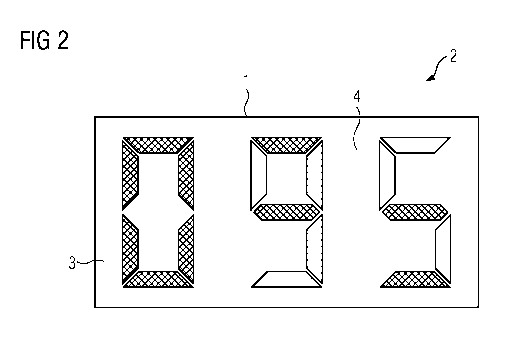
In order to provide a locomotive driver's cab which allows the locomotive driver a comparatively long time for observing the route, the locomotive driver's cab is equipped with a front vision display (3) with displaying (4) of rail-vehicle-relevant information in the field of vision of the locomotive driver.


French Abstract

L'invention vise à créer un poste de conduite de locomotive qui laisse au conducteur de la locomotive une part de temps relativement longue pour observer la voie. A cet effet, le poste de conduite de locomotive est équipé d'un affichage tête haute (3) avec un affichage (4) des informations significatives pour le véhicule ferroviaire dans le champ de vision du conducteur.

Claims

Note: Claims are shown in the official language in which they were submitted.


- 6 -
Claims
1. A locomotive driver's cab with a front-view display (3) with
a display (4) of information relevant to the railway vehicle
in the field of view of the driver of the locomotive.
2. The locomotive driver's cab as claimed in claim 1,
characterized in that
the windscreen (2) of the railway vehicle is the projection
screen (3) of the front-view display.
3. The locomotive driver's cab as claimed in claim 1 or 2,
characterized in that
the imaging unit of the front-view display is connected to
the operating system of the vehicle controller and the
operating system of the train protection means.
4. The locomotive driver's cab as claimed in any one of the
preceding claims,
characterized in that
the imaging unit of the front-view display is connected to
an evaluation device of a camera system at the front of the
railway vehicle that is designed such that the track route
is displayed on the projection screen in each case.
5. The locomotive driver's cab as claimed in claim 4,
characterized in that
the evaluation device is designed such that the track route
is marked on the projection screen with a stopping point
assuming full braking.
6. The locomotive driver's cab as claimed in claim 4 or 5,
characterized in that
the evaluation device is designed such that the track route

- 6a -
is displayed on the projection screen with detection of
obstructions in each case.

- 7 -
7. The locomotive driver's cab as claimed in any one of the
preceding claims,characterized in that
the imaging unit supplied with two similar types of
information from different systems is designed such that it
outputs optical signals of different color for the
information from the different systems, and the optical
module of the windscreen display contains two mirror systems
in such an alignment that the optical signals relating to
different information are incident at the same point on the
projection screen (3).
8. The locomotive driver's cab as claimed in claim 7,
characterized in that
the two similar types of information are safety-relevant
information.
9. The locomotive driver's cab as claimed in claim 7 or 8,
characterized in that
the two similar types of information are speed information
and the optical signals relevant to the different speed
information each produce a seven segment display (4) on the
same point of the projection screen.

Description

Note: Descriptions are shown in the official language in which they were submitted.


CA 02849935 2014-03-25
PCT/EP2012/068936 - 1 -
2011P21463W0US
Description
Locomotive Driver's Cab
At present- as can be seen from the periodical "ETR", September
2010, No. 09, pages 532 to 538 - there is work on the
standardization and harmonization of the functional arrangement
and design of a future European driver's cab for locomotives
and traction units. Within this work the concept of a
locomotive driver's cab having four displays that are disposed
in a ring arrangement beneath the windscreen of the locomotive
driver's cab has been developed. While the railway vehicle is
traveling, the locomotive driver must monitor the track and
must additionally observe the four displays.
The object of the invention is to propose a locomotive driver's
cab which allows the locomotive driver more time to observe the
track and thus contributes to increasing safety in rail
traffic.
In order to achieve said objective, according to the invention
a locomotive driver's cab with a front-view display with a
display of information relevant to the railway vehicle in the
field of view of the driver of the locomotive is suitable.
There are front-view displays known from
http://de.wikipedia.org/wiki/Head-up-Display, which are used in
military aircraft for displaying information relating to
avionic, radar or weapon systems and in automobiles for speed
displays, but to date it has not been known that in modern
locomotive driver's cabs with relatively many displays the use
of front view displays brings significant advantages with it.
There is thus a significant advantage of the locomotive
driver's cab according to the invention in that with it the
information relevant to the railway vehicle is disposed in the

CA 02849935 2014-03-25
PCT/EP2012/068936 - la -
2011P21463W0US
field of view of the driver of the locomotive and can therefore
be perceived by the driver together with the track observation.
The locomotive driver therefore has to

CA 02849935 2014-03-25
PCT/EP2012/068936 - 2 -
2011P21463W0US
take notice of the displays less often than hitherto and can
concern himself more intensively than previously with track
observation. This also contributes to increasing traffic
safety.
With the locomotive driver's cab according to the invention,
the projection screen of the front-view display can be designed
differently; for example, the projection screen can be disposed
as an additional projection panel in front of or behind the
windscreen of the locomotive driver's cab in the field of view
of the driver of the locomotive. It is seen as particularly
advantageous, however, if the windscreen of the railway vehicle
is the projection screen of the front-view display.
The imaging unit of the front-view display is advantageously
connected to important systems of a railway vehicle in order to
be able to access information relevant to the railway vehicle
and to be able to display this on the projection screen of the
front-view display. It is therefore advantageous that the
imaging unit of the front-view display is connected to the
operating system of the vehicle controller and is connected to
the operating system of the train protection system.
It is seen as particularly advantageous if the imaging unit of
the front-view display is connected to an evaluation device of
a camera system at the front of the railway vehicle designed
such that the respective track route is displayed on the
projection screen.
There is then also the advantageous possibility of designing
the evaluation device such that the respective track route is
marked on the projection screen with a stopping point assuming
full braking and is thus easy to read for the locomotive
driver.

CA 02849935 2014-03-25
PCT/EP2012/0.68936 - 2a -
2011P21463W0US
It is further advantageous regarding the increase in traffic
safety if the evaluation device is designed such that in each
case the track route is displayed while recording obstructions
on the projection screen.
=

CA 02849935 2014-03-25
PCT/EP2012/068936 - 3 -
2011P21463W0US
It contributes to the further facilitation of the work of the
driver of the locomotive and to increased traffic safety if in
the locomotive driver's cab according to the invention the
image generating unit, being supplied with two similar types of
information from different systems, is designed such that it
outputs optical signals of different colors for the information
from the different systems, and the optical module of the
windscreen display contains two mirror systems in such an
orientation that the optical signals relating to different
information are incident in the same place on the projection
screen. If the information from the two systems is the same
then this results in a display on the projection screen with
mixed colors that is easy to read; if on the other hand the
information is different, this results in a display with a
different color and a different shape. The locomotive driver
can thus tell immediately that the information no longer
agrees, which points to impaired information generation in one
of the two systems.
The two similar types of information can advantageously be
safety-relevant information.
It is also advantageous if the two similar types of information
are speed information and the optical signals relating to the
different speed information each produce a seven segment
display at the same point on the projection screen. If the
speed information is the same, this results in an easily
legible seven segment display in a uniform mixed color. If the
two items of speed information differ from each other, this
results in information on the projection screen of the front-
view display that is not easily legible, because two different
seven segment displays are overlaid and a non-uniform color
image results.
For further explanation of the invention, a section of a
windscreen forming the projection screen of a front-view display
of the locomotive driver's cab according to the invention is

CA 02849935 2014-03-25
PCT/EP2012/068936 - 3a -
2011P21463W0US
illustrated in Figure 1

CA 02849935 2014-03-25
PCT/EP2012/068936 - 4 -
2011P21463WOUS
with a correct display of a speed and in Fig. 2 the same
section is illustrated but with an incorrect display.
The section 1 shown in Figures 1 and 2 of a windscreen 2 of a
locomotive driver's cab, which is not illustrated further, also
forms a section of the projection screen 3 of a front-view
display that is not illustrated further, which apart from the
projection screen 3 comprises an imaging unit and an optical
module in a known manner. The imaging unit is, however,
implemented with two imaging devices in this case, such that it
can be provided with speed information from two systems of the
railway vehicle and outputs optical signals of different color,
e.g. green and yellow. Accordingly, the optical module is
equipped with two mirror systems, which are arranged such that
they direct optical signals onto the illustrated section 1 one
above the other, forming a seven segment display 4 of the speed
of the railway vehicle.
Figure 1 shows a correct seven segment display 4 with the speed
information "087". Here the green (right hashed) and yellow
(left hatched) illuminated segments of the seven segment
display 4 from the two imaging devices are fully aligned with
each other. The speed information is therefore easy to read for
the locomotive driver on all segments because of the uniform
blue mixed color (cross-hatched) and moreover it signals to the
driver that the speed measurement with the two systems of the
railway vehicle is correct.
Fig. 2 shows an impaired speed display in which "0" is
correctly reproduced because it uniformly shows the blue mixed
color. But this no longer applies with regard to the other
numbers, which have blue areas (cross-

CA 02849935 2014-03-25
=
PCT/EP2012/068936 - 5 -
2011P21463W0US
hatched), green areas (right hatched) and a yellow area (left
hatched) and hence notify the locomotive driver of a faulty
speed determination.

Representative Drawing
A single figure which represents the drawing illustrating the invention.
Administrative Status

For a clearer understanding of the status of the application/patent presented on this page, the site Disclaimer , as well as the definitions for Patent , Administrative Status , Maintenance Fee  and Payment History  should be consulted.

Administrative Status

Title Date
Forecasted Issue Date Unavailable
(86) PCT Filing Date 2012-09-26
(87) PCT Publication Date 2013-04-04
(85) National Entry 2014-03-25
Examination Requested 2014-03-25
Dead Application 2016-11-09

Abandonment History

Abandonment Date Reason Reinstatement Date
2015-11-09 R30(2) - Failure to Respond
2016-09-26 FAILURE TO PAY APPLICATION MAINTENANCE FEE

Payment History

Fee Type Anniversary Year Due Date Amount Paid Paid Date
Request for Examination $800.00 2014-03-25
Application Fee $400.00 2014-03-25
Maintenance Fee - Application - New Act 2 2014-09-26 $100.00 2014-08-08
Maintenance Fee - Application - New Act 3 2015-09-28 $100.00 2015-08-12
Owners on Record

Note: Records showing the ownership history in alphabetical order.

Current Owners on Record
SIEMENS AKTIENGESELLSCHAFT
Past Owners on Record
None
Past Owners that do not appear in the "Owners on Record" listing will appear in other documentation within the application.
Documents

To view selected files, please enter reCAPTCHA code :


To view images, click a link in the Document Description column. To download the documents, select one or more checkboxes in the first column and then click the "Download Selected in PDF format (Zip Archive)" or the "Download Selected as Single PDF" button.

List of published and non-published patent-specific documents on the CPD .

If you have any difficulty accessing content, you can call the Client Service Centre at 1-866-997-1936 or send them an e-mail at CIPO Client Service Centre.


Document
Description 
Date
(yyyy-mm-dd) 
Number of pages   Size of Image (KB) 
Abstract 2014-03-25 1 64
Claims 2014-03-25 3 60
Drawings 2014-03-25 1 26
Description 2014-03-25 8 189
Representative Drawing 2014-03-25 1 13
Cover Page 2014-05-14 1 39
PCT 2014-03-25 19 622
Assignment 2014-03-25 2 65
Prosecution-Amendment 2015-05-07 4 265
Correspondence 2015-01-15 2 66