Note: Descriptions are shown in the official language in which they were submitted.
CA 02849943 2014-03-25
WO 2013/057366 PCT/F12012/050964
SEPARATING DEVICE AND METHOD FOR A PNEUMATIC MATERIAL
CONVEYING SYSTEM
Background of the invention
The object of the invention is a method as defined in the preamble of claim 1.
The object of the invention is also an apparatus as defined in claim 10.
The invention relates generally to pneumatic material conveying systems, such
as
to partial-vacuum transporting systems, more particularly to the collection
and
conveying of wastes, such as to the conveying of household wastes. Such
systems are presented in publications WO 2009/080880, WO 2009/080881, WO
2009/080882, WO 2009/080883, WO 2009/080884, WO 2009/080885, WO
2009/080886, WO 2009/080887 and WO 2009/080888, among others.
Pneumatic material conveying systems wherein wastes are conveyed in piping by
means of suction, a pressure difference and/or a flow of transporting air are
known
in the art. Pneumatic pipe transporting systems for material are used, among
other
things, for the conveying of wastes in different buildings, in institutions or
in more
extensive areas, e.g. in blocks or city districts. It is typical to these
systems that a
partial-vacuum apparatus is used to achieve a pressure difference, in which
apparatus a partial vacuum, a pressure difference and/or a flow of
transporting air
is achieved in the conveying pipe with partial-vacuum generators, such as with
vacuum pumps or with an ejector apparatus or with fans. The wastes transfer
from
the input point along the piping together with the transporting air into a
separating
device, which is e.g. a cyclone separator or some other tank, in which the
material
to be conveyed is separated from the transporting air. The transporting air
exits
from the output aperture for transporting air and the waste remains in the
separating device, from where it is removed, e.g. according to need. The
transporting air and the waste are typically brought into the chamber of the
separating device tangentially, in which case a rotating movement is achieved
in
the separating chamber and the transporting air and waste to be separated
circulate in the separating device typically near the walls, in which case the
heavier waste remains in the separating device and the transporting air rises
upwards from the center of the cyclone separator. One problem is that papers
and
thin plastics that are light and have a large surface area can sometimes
ascend
CA 02849943 2014-03-25
WO 2013/057366 PCT/F12012/050964
2
along with the ascending transporting air flow. There are often waste grades,
e.g.
waste paper, plastic film, plastic bags, et cetera, along with the waste being
transported, which waste grades, being unattached and lighter than the other
waste, can block the output aperture for the transporting air of the
separating
device or other tank, either partly or completely. A problem with a separating
device, such as a cyclone separator or other tank, is therefore that with
waste
generally e.g. paper and thin plastic try to block the output aperture for the
transporting air of the separating device. Problematic waste grades, e.g.
paper
and plastic, typically have a large surface area and low weight. These often
cause
problems for a separator because problematic waste grades float very easily to
the
output aperture for the transporting air. Efforts have been made to solve this
problem by using various mechanical means, e.g. rotating brushes, to prevent
blockage of the output aperture and, on the other hand, to remove rubbish that
has
gone into it. These have not, however, functioned satisfactorily.
The aim of the present invention is to achieve a completely new type of
solution in
connection with the separating devices of pneumatic material conveying
systems,
by means of which solution the drawbacks of prior-art solutions are avoided.
Another aim of the invention is to achieve a solution applicable in connection
with
a pneumatic wastes conveying systems, by the aid of which blocking of the
output
aperture of a separating device can be prevented more easily than before and,
on
the other hand, blockages of the output aperture for the transporting air of
the
separating device can be removed. Yet another aim is to achieve a solution, by
means of which the separating efficiency of a separating device can be
improved.
Brief description of the invention
The invention is based on a concept wherein a flow of transporting air is
arranged
in a separating device of a pneumatic material conveying system, such that the
circulation direction of the input air and of the output air is changed, in
which case,
as a consequence of this, the passage of waste particles, such as paper or
plastic
films or bags, into the output aperture for the transporting air and/or the
blocking of
the output aperture is reduced or prevented.
The method according to the invention is mainly characterized in that in the
method the flow of transporting air is acted upon in the chamber space of the
CA 02849943 2014-03-25
WO 2013/057366 PCT/F12012/050964
3
separating device or in the output channel by bringing about a guiding effect
for
the transporting air in the opposite direction with respect to the direction
of rotation
of said transporting air.
The method according to the invention is also characterized by what is stated
in
claims 2 ¨ 9.
The apparatus according to the invention is mainly characterized in that
guiding
means of the transporting air flow are arranged in the separating device,
which
guiding means are configured to bring about in the flow of transporting air in
the
chamber space of the separating device or in the output channel a guiding
effect
for the transporting air in the opposite direction with respect to the
direction of
rotation of said transporting air.
The apparatus according to the invention is also characterized by what is
stated in
claims 11 ¨ 17.
The solution according to the invention has a number of significant
advantages. By
acting upon the flow of transporting air in the chamber space of the
separating
device or in the output channel by bringing about a guiding effect for the
transporting air in the opposite direction with respect to its direction of
rotation, it is
possible to significantly improve prevention of the material to be separated
displacing along with the transporting air towards the output channel. In this
case
e.g. waste particles, such as papers or plastic films or bags, do not go into
the
output aperture and/or block the output aperture, and a separating device for
a
pneumatic wastes conveying system that is more operationally reliable than
before
can be achieved. The desired effect can be achieved by arranging an output
branch coupling in the wall of the output channel such that a flow of the
transporting air from the output channel into the output branch coupling is
achieved in a mainly tangential direction with respect to the wall of the
output
channel. This can be achieved e.g. by arranging the output branch coupling
eccentrically in the output channel. With the solution according to the
invention a
significant improvement in the operation of a separating device of a pneumatic
waste conveying system is achieved in a rather cost-effective manner.
Brief description of the figures
CA 02849943 2014-03-25
WO 2013/057366 PCT/F12012/050964
4
In the following, the invention will be described in more detail by the aid of
an
embodiment with reference to the attached drawings, wherein
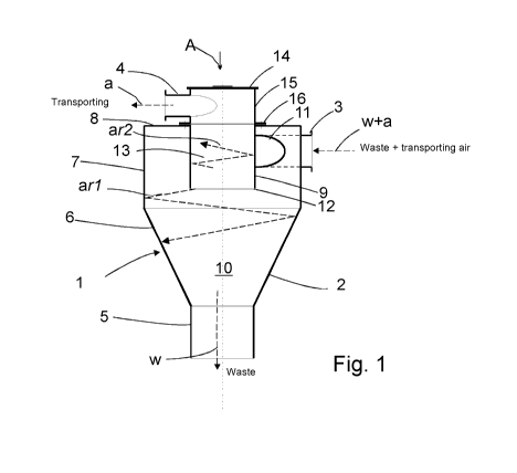
Fig. 1 presents a simplified and sectioned view of a separating device of an
embodiment of the invention,
Fig. 2 presents the device of the embodiment of Fig. 1 from the direction of
the
arrow A.
Detailed description of the invention
In a pneumatic material conveying system, such as in a wastes conveying
system,
the material fed into the conveying piping from an input point is transported
along
the conveying piping to a separating device 1, in which the material being
transported separates, e.g. due to the dropping of speed and due to
centrifugal
force, from the transporting air.
Fig. 1 presents a simplified view of a separating device 1 of a pneumatic
material
conveying system, more particularly a wastes conveying system, according to an
embodiment according to the invention. In the embodiment of the figure, the
separating device 1 is a so-called cyclone separator comprising a chamber
space
10 that is bounded by walls 2, 8. At its top part 7 the chamber space 10 is
wider,
mainly cylindrical and tapers conically at its center part 6 towards the
bottom part
5. An input branch coupling 3 is connected to the wall 2 of the separating
device,
to the top part 7 of it, via which branch coupling the material to be
transported,
such as waste material, is conducted together with the transporting air into
the
chamber space 10 of the separating device from the input aperture 11. The
input
aperture 11 is arranged in the wall 2 of the chamber space of the separating
device, in the top part 7 of its side wall.
In the embodiment of the figure, the input aperture 11 of the input branch
coupling
3 into the chamber space 10 is arranged in the wall 2 of the separating
device, in
the top part 7 of said wall, in the area between the butt end wall 8 and the
bottom
part 12 of the wall 9 of the output channel 12 extending into the inside part
of the
separating device. The chamber space 10 in the separating device 1 thus
comprises a ring-like section in the aforementioned area, in which the wall 9
forms
CA 02849943 2014-03-25
WO 2013/057366 PCT/F12012/050964
the inner rim of the ring-like section and the wall 2 of the separating
device,
typically the top part 7 of the wall, forms the outer rim of the ring-like
section.
In the embodiment of Figs. 1 and 2, the input branch coupling 3 is arranged in
the
wall such that the transporting air and the solid particles are fed into a
mainly
5 tangential movement in the chamber space 10, in the top part of it.
In the embodiment of the figure, the material, such as waste material,
separated
from the transporting air drifts to the bottom part 5 of the separating device
1, from
where it is removed continuously or from time to time. In Fig. 1, the drifting
of the
separated material to the bottom part of the chamber space 10 of the
separating
device 1 is described with the arrow (w). The separated material is removed,
e.g.
according to need, from the separating device, e.g. via a material output
aperture
arranged in the bottom part 5 of the chamber space 10 of the separating
device.
The transporting air is conducted from the separating device with an output
branch
coupling 4 for the transporting air. The transporting air is typically
deflected in the
separating device, in which case the heavier material accompanying the
transporting air separates from the transporting air more easily.
In the embodiment of the figure, a wall part 9 is arranged in the top part of
the
separating device, which wall part extends into the chamber space 10 of the
separating device. In the embodiment of the figure, the wall part 9 is
cylindrical. In
the figure, the wall part is on the same axis as (is coaxial with) the
vertical axis of
the chamber space 10 of the separating device. An output channel 13 is formed
on
the inside of the rim of the wall part 9, into which output channel the
aperture of
the bottom part of the wall 9, i.e. the output aperture 12, leads. There is a
connection from the top part of the output channel 13 to the output branch
coupling 4 for transporting air.
In the embodiment of the figure, the lower end of the cylindrical wall part 9
is open.
An output branch coupling 4 for the transporting air is arranged in the top
part 15
of the wall part 9. In the embodiment of the figure, the output channel 13
extends
through the top end, such as through the top wall 8, of the separating device,
e.g.
from an aperture formed in the top wall 8. In the figure, the cylindrical wall
part 9
and the output channel 13 comprise a wall section 15 that is outside the top
wall 8
of the chamber space 10 of the separating device. The wall section 15 that is
outside the wall part 9, preferably outside the chamber space 10 of the
separating
CA 02849943 2014-03-25
WO 2013/057366 PCT/F12012/050964
6
device, comprises an end plate in its upper end. An output branch coupling 4
for
the transporting air is arranged in the top part of the wall part 9. The
transporting
air is conducted from the chamber space 10 via the output channel 13 of the
wall
part 9 into the output branch coupling 4. The output branch coupling 4 is, in
the
embodiment of Figs. 1 and 2, arranged in the wall section 15 such that the
transporting air is exhausted in a mainly tangential movement from the output
channel 13, from the top part of it.
A tangential movement has been achieved for the outgoing transporting air in
the
output channel 13, which movement is preferably in the opposite direction with
respect to the tangential movement of the transporting air (and the particles
transported along with it) (w+a) in the chamber space 10 of the separating
device,
at least in the proximity of the input branch coupling 3 in the chamber space
10.
The movement of the transporting air in the separating device is roughly
illustrated
with the arrow a and with w+a, where a presents the movement of the
transporting
air leaving the separating device and w+a the movement of the transporting air
and waste particles coming into the separating device at least in the
proximity of
the input aperture.
In the separating device, the flow rate of the incoming transporting air in
the input
branch coupling 3 is in one embodiment 15 ¨ 30 m/s. The speed of the
transporting air in the output channel is approx. 10 ¨ 15 % of this, i.e. 1.5
¨ 5 m/s.
Since the transporting air and the particles to be separated coming into the
separating device are brought tangentially into the chamber of the separating
device, a rotating movement of the air flow and the particles to be separated
is
achieved in the chamber space 10 of the separating device. In this case the
air
flow in the center of the separating device rotates and this eddy rises into
the
output channel, in which case the speed of it in the vortex can rise by a
multiple
factor. To prevent this phenomenon, an output branch coupling 4 is arranged in
the top end of the separating device such that it produces, when the suction
side
(not presented) of at least one partial-vacuum generator of a pneumatic
material
conveying system is connected to the output branch coupling 4, a tangential
movement (eddy) of the transporting air in the output channel 13. The
tangential
movement of the transporting air is thus opposite with respect to the rotation
direction of the tangential movement of the transporting air coming into the
separating device from the input branch coupling 3. In this case the rotating
movement of the transporting air coming in from the chamber space 10 is
CA 02849943 2014-03-25
WO 2013/057366 PCT/F12012/050964
7
neutralized in the output channel 13, or in the proximity of it, and the speed
of the
transporting air decelerates. With this procedure the easy ascent of
detrimental
particles, such as paper and plastic, along with the transporting air from the
chamber space 10 of the separating device into the output channel 13 is
prevented.
The invention relates to a method for improving the separating efficiency of a
separating device 1 of a pneumatic material conveying system, such as of a
waste
conveying system, in which the material to be transported, such as waste
material
w, is separated from the transporting air a, and/or for preventing blocking of
the
output aperture for the transporting air of the separating device, in which
method
the transporting air and the material coming with it w+a are initially brought
into a
rotating movement an in the chamber space 10 of the separating device, the
transporting air a is deflected in the chamber space 10 of the separating
device,
and is conducted into the output channel 13. In the method the flow of
transporting
air is acted upon in the chamber space 10 of the separating device or in the
output
channel 13 by bringing about a guiding effect for the transporting air in the
opposite direction with respect to its direction of rotation an.
According to one embodiment a guidance effect is achieved for the transporting
air
in the output channel 13 in the opposite direction with respect to the
rotating
movement an of the transporting air being achieved in the chamber space 10 of
the separating device.
According to one embodiment a rotating movement ar2 is achieved in the chamber
space by conducting with the input branch coupling 3 the transporting air and
the
. material to be separated in a mainly tangential direction with respect to
the wall of
the chamber.
According to one embodiment the transporting air in the output channel 13 is
acted
upon by arranging an output branch coupling 4 in the wail 9 of the output
channel
such that a flow of the transporting air from the output channel 13 into the
output
branch coupling 4 is achieved in a mainly tangential direction with respect to
the
wall of the output channel.
According to one embodiment a flow of transporting air is achieved between the
input branch coupling 3 and the output branch coupling 4 of the separating
device
CA 02849943 2014-03-25
WO 2013/057366 PCT/F12012/050964
8
via the chamber space 10 by connecting the output branch coupling 4 to a
medium
pathway leading to the suction side of a partial-vacuum generator of a
pneumatic
material conveying system.
According to one embodiment the flow rate of the transporting air is slowed
down
between the input branch coupling 3 and the output branch coupling 4.
According to one embodiment the output channel 13 is arranged coaxially with
the
vertical axis of the separating device 1.
According to one embodiment the separating device 1 is a cyclone separator.
According to one embodiment the separating device 1 is a separating device or
waste tank of a pneumatic wastes conveying apparatus.
The invention also relates to an apparatus for improving the separating
efficiency
of a separating device of a pneumatic material conveying system, in which the
material to be transported, such as waste material w, is separated from the
transporting air a, and/or for preventing blocking of the output aperture for
the
transporting air of the separating device, which separating device 1 comprises
a
chamber space 101 and also an input branch coupling 3 for the material to be
transported and the transporting air, means for bring the transporting air and
the
material coming with it w+a initially into a rotating movement an in the
chamber
space 10 of the separating device, means for deflecting the transporting air a
in
the chamber space 10 of the separating device and for conducting said
transporting air into the output channel 13. Guiding means of the transporting
air
flow are arranged in the separating device 1, which guiding means are
configured
to bring about in the flow of transporting air in the chamber space 10 of the
separating device or in the output channel 13 a guiding effect for the
transporting
air in the opposite direction with respect to its direction of rotation an.
According to one embodiment the guiding means of the transporting air flow
comprise an output branch coupling 4, which is arranged eccentrically in the
wall 9
of the output channel 13.
CA 02849943 2014-03-25
WO 2013/057366 PCT/F12012/050964
9
According to one embodiment the output branch coupling 4 is arranged in the
wall
9 of the output channel 13 in a mainly tangential direction with respect to
the wall
of the output channel.
According to one embodiment the output channel 13 is arranged coaxially with
the
vertical axis of the separating device 1.
According to one embodiment the output channel 13 is mainly cylindrical and
open
at its bottom part 12.
According to one embodiment the separating device is configured to be
connected
from the output branch coupling 4 to a medium pathway leading to the suction
side
of a partial-vacuum generator of a pneumatic material conveying system.
According to one embodiment the separating device 1 is a cyclone separator.
According to one embodiment the separating device 1 is a separating device or
waste tank of a pneumatic wastes conveying apparatus.
It is obvious to the person skilled in the art that the invention is not
limited to the
embodiments presented above, but that it can be varied within the scope of the
claims presented below. The characteristic features possibly presented in the
description in conjunction with other characteristic features can also, if
necessary,
be used separately to each other.