Note: Descriptions are shown in the official language in which they were submitted.
CA 02850002 2014-03-25
WO 2013/050843 PCT/1B2012/001727
1
A method for binding leaves and a binding element and
binding device applied thereto.
The present invention relates to a method for binding
leaves and a binding element and binding device applied
thereto.
For binding it is known to make use of a conventional
binding element in the form of a folder with a U-shaped
back with a base and two upright arms and two cover sheets
that are each connected by an edge to an edge of one of the
arms of the back, whereby the inside of the back, more
specifically at least a part of the base of the back, is
provided with a hot-melt adhesive.
Hot-melt adhesive here means an adhesive that is hard at
room temperature and which becomes liquid upon heating, and
after cooling to room temperature becomes hard again.
In order to bind a bundle of loose leaves, a free edge to
be bound of the bundle is pushed into the back up against
the hot-melt adhesive, and the folder is placed, with its
back downwards, on a heating element of a binding device
provided to this end, in order to raise the hot-melt
adhesive to a sufficiently high temperature to melt the
adhesive.
The leaves of the bundle thus sink as it were, with the
aforementioned edge to be bound, into the molten hot-melt
adhesive.
CA 02850002 2014-03-25
WO 2013/050843 PCT/1B2012/001727
2
Then the back of the binding element with the bundle of
leaves in it is allowed to cool, such that the hot-melt
adhesive solidifies again and the leaves are as it were
bonded to the base of the back.
A problem that arises is that during binding not all the
leaves of the bundle sink into the molten adhesive, or do
not sink in sufficiently deeply, in order to obtain a good
bond. This problem primarily occurs with the outermost
leaves of the bundle, possibly because when securing the
folder in the device they are somewhat held back by the
cover sheets that are held together by the user in order to
secure the folder to the bundle therein.
Another problem is that preferably a relatively large
number of different sizes of back widths of the binding
elements must be kept in stock.
Indeed, a good binding result is only obtained if the
thickness of the bundle of leaves to be bound fits
relatively closely between the arms of the back.
For a given thickness of a bundle, a binding element is
thus chosen with a-suitable back width.
With the known binding systems of the aforementioned type
12 sizes of back widths are available are example, from
1 mm to 36 mm, each with a few millimetres difference
between successive sizes.
CA 02850002 2014-03-25
WO 2013/050843 PCT/1B2012/001727
3
In the absence of the right size of back width, it is
sometimes attempted to resort to a back with an oversized
back width whose opening between the arms of the back is
then artificially narrowed by squeezing the ends of the
arms partly closed.
However, this rarely or never leads to a satisfactory
result as it is difficult to squeeze the arms closed
uniformly, and moreover the base of the back becomes
bulbous as a result, such that the contact with the heating
element of the binding device is not optimum, resulting in
a poor bond.
The purpose of the present invention is to provide a
solution to at least one of the aforementioned and other
disadvantages.
To this end the invention concerns a method for binding a
bundle of leaves in a binding element in the form of a
folder with a U-shaped back of a pliable and thermally
conductive material, preferably steel, with a base and two
upright arms and two cover sheets that are each connected
by an edge to a free edge of the arms, whereby a hot-melt
adhesive is provided on the inside of the back, at least on
a part of the base of the back, and whereby the method
consists of introducing the bundle of leaves, with the edge
to be bound against the hot-melt adhesive in the back, and
then heating up the back to melt the hot-melt adhesive,
characterised in that an oversized binding element is
chosen in which the bundle with the thickness of the edge
to be bound is received with a certain sideways play
CA 02850002 2014-03-25
WO 2013/050843 PCT/1B2012/001727
4
between the arms of the back, and that the folder with the
bundle therein and the hot-melt adhesive in the molten
state, is placed with the base of the back on a seat that
fits closely to the base with the arms between two parallel
pressure bars that are moved towards one another with a
force in order to press the base of the back against the
seat and at the same time to fold the arms symmetrically
towards one another at an angle with respect to the base
until the bundle, with a desired force from the pressure
bars, is clamped in between the arms of the back, after
which the pressure bars, possibly after a short period
during which the force has been maintained, are again moved
away from one another in order to be able to remove the
bound folder, whereby the desired force is chosen such that
by clamping in the bundle a force is exerted on the bundle
that is directed towards the base of the back.
An advantage is that when folding the arms of the back, the
free ends of the arms and the cover sheets of the binding
element attached thereto are moved closer to the back,
whereby these ends and/or cover sheets pull the bundle, and
in particular the outermost leaves of the bundle, towards
the back and the edge to be bound of the bundle is thereby
firmly pushed into the molten adhesive, whereby it is
guaranteed, that after the adhesive has cooled, all leaves
are firmly secured in the adhesive.
Another advantage is that when clamping in the back it is
perfectly secured in its place on the seat, which fosters
the symmetrical squeezing close of the arms of the back.
CA 02850002 2014-03-25
WO 2013/050843 PCT/1B2012/001727
An advantage of this symmetry is of an aesthetic nature.
Another advantage of the method is that the back fits
perfectly with the clamped bundle, and there is thus no gap
between the free ends of the arms through which the
adhesive could be seen in the back, which also contributes
to the professional appearance of the bound folder.
Another important advantage is that bundles of different
thicknesses can be bound in the same binding element, so
that the entire range of the usual bundle thicknesses can
be bound with a limited number of sizes of binding
elements.
By using the force as a control parameter of the method,
the method is independent of the thickness of the back of
the chosen binding element, such that an extra adjustment
is not required whenever different sizes of folders are
used.
The invention also relates to a binding device for use in
the method as described above, whereby the device is
provided with a seat for the close-fitting support of the
base of the back of a folder to be bound that is placed
with this base on the seat, two parallel pressure bars that
extend on either side of the seat and above the level of
the seat, and means for moving the pressure bars towards
one another with a certain force in order to fold the arms
of the back of the folder on the seat towards one another
symmetrically at an angle with respect to the base. Means
for determining the force exerted by the pressure bars and
CA 02850002 2014-03-25
WO 2013/050843 PCT/1B2012/001727
6
means to again move the pressure bars away from one another
when the thus determined force has reached a certain
desired value, possibly after this force has been
maintained for a short period.
This device has the advantage that the arms are folded
perfectly symmetrically and that the device does not
require any adjustment, not even when different sizes of
binding elements are used after one another.
The invention also relates to a binding element in the form
of a folder that is suitable for use in a method and with a
binding device as described above, and this binding element
is constructed in the form of a folder with a U-shaped back
of a pliable and thermally conductive material, preferably
steel, with a base and two upright arms and two cover
sheets that are each connected by an edge to a free edge of
the arms, whereby a hot-melt adhesive is provided on the
inside of the back, at least on a part of the base of the
back, characterised in that the arms of the binding element
are of such a height that the free ends of the arms can be
folded against one another, when they are folded towards
one another symmetrically over an angle with respect to the
seat.
Such a binding element offers the advantage that very thin
bundles can also be bound, irrespective of the width of the
back of the chosen binding element.
Thus for example with a binding element with a back width
of approximately 15 mm and a height of the arms of the back
CA 02850002 2014-03-25
WO 2013/050843 PCT/1B2012/001727
7
of approximately 10 to 11 mm, 90% of the commonest
thicknesses of the bundles of leaves to be bound can be
bound with a single size of binding element.
With the intention of better showing the characteristics of
the invention, a preferred embodiment of a binding element
and binding device according to the invention, and this for
the application of a method according to the invention, is
described hereinafter by way of an example, without any
limiting nature, with reference to the accompanying
drawings, wherein:
Figure 1 schematically shows a cross-section of a
binding element according to the invention;
figure 2 shows the part indicated in figure 1 by F2 on
a larger scale;
figures 3 to 6 show successive steps during the
binding of a bundle of leaves according to the method
of the invention, in a binding element according to
figure 1, whereby figure 4 is an enlargement of the
part indicated in figure 3 by F4;
figure 7 is an illustration of the last step of the
aforementioned method as shown in figure 6, but this
for binding a thinner bundle;
figure 8 schematically shows a perspective cutaway
view of a binding device according to the invention
for application of a method according to the
invention;
figure 9 shows a side view according to arrow F9 in
figure 8;
CA 02850002 2014-03-25
WO 2013/050843 PCT/1B2012/001727
8
figure 10 shows the part indicated in figure 9 by box
F10 on a larger scale;
figures 11 to 14 show successive steps of the use of
the binding device according to figures 8 to 10 for
application of the method according to the invention.
The binding element 1 of figure 1 primarily consists of a
folder with a U-shaped back 2 that is manufactured from a
pliable, more specifically a plastically pliable, and
thermally conductive material, preferably steel, with a
base 3 and two upright arms 4 and two cover sheets 5 that
are each connected by an edge 6 to a free edge 7 of the
arms 4.
The binding element 1 is provided with a hot-melt adhesive
8 on the inside of the back 2, in particular at least on a
part of the base of the back 3.
The hot-melt adhesive 8 in the back 2 preferably extends
over almost the entire length of the back, and in the
example shown extends to the inside of the arms 4, although
this is not strictly necessary.
In this case the cover sheets 5 are connected to the arms 4
of the back 2 by a film hinge 9, which is formed for
example by a covering 10 that is affixed around the cover
sheets 5 and which runs up to the back 2 on which the
covering is secured, for example because it goes around the
back 2 and is bonded to it, for example by means of a cold-
set adhesive.
CA 02850002 2014-03-25
WO 2013/050843 PCT/1B2012/001727
9
Generally the back 2 of the binding element 1 is
manufactured from metal, preferably steel, or another
material that is thermally conductive to efficiently and
evenly distribute the heat of the binding device over the
material of the back 2 as well as over the hot-melt
adhesive 8.
In the example shown, the base 3 of the back 2 is
constructed flat.
The use of the binding element 1 described above for the
application of the method according to the invention is
illustrated on the basis of figures 3 to 6.
According to the invention an oversized binding element 1
is hereby assumed with a width of the back 2 that is such
that the distance A between the arms of the back is
greater, for example at least 4 mm greater, than the
thickness B of a bundle of loose leaves 11 to be bound.
Figure 3 starts with a situation in which the bundle of
loose leaves 12 to be bound is introduced between the cover
sheets 5 of the binding element 1.
The edge 12 to be bound of the bundle 11 is thereby
introduced in the back 2 with a certain sideways play C,
due to the oversized choice of the binding element 1, and
is thereby in contact with the hot-melt adhesive 8.
The binding element 1 with the bundle 11 in it is placed
upright with the base 3 of the back 2 on a heating element
CA 02850002 2014-03-25
WO 2013/050843 PCT/1B2012/001727
13 that is suitable for heating the back 2 and the
aforementioned edge 12 of the bundle 11 to a sufficiently
high temperature in order to melt the hot-melt adhesive 8.
When the hot-melt adhesive 8 is molten, the edge 12 of the
bundle of leaves 11 to be bound sinks into the molten
adhesive 8, whereby it often occurs, as shown in figure 4,
that the outermost leaves 14 of the bundle 11 do not sink,
or do not sink sufficiently deeply, into the hot-melt
adhesive 8, possibly because they are somewhat held back by
the contact with the cover sheets 5.
In a next step of the method according to the invention, as
illustrated in figure 5, the binding element 1 with the
bundle 11 therein and the adhesive 8 in the molten state,
with the base 3 placed on a close fitting unheated flat
seat 15 and a force is exerted on either side of the back 2
in order to fold the arms 4 of the back 2 towards one
another in a symmetrical way with respect to the plane of
symmetry X-X' of the back, which runs parallel to the arms
4, whereby the arms 4 with the base 3 of the back 2 enclose
the same symmetrical angle D as illustrated on the basis of
figure 5.
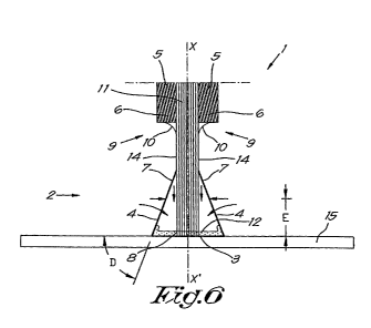
In a next step, as shown in figure 6, the arms 4 are moved
further towards one another until the aforementioned force
has reached a desired value.
It is clear that due to the downward movement of the free
ends 7 of the arms 4 in the direction of the base 3 of the
back 2, a force is exerted in this direction that pushes
CA 02850002 2014-03-25
WO 2013/050843 PCT/1B2012/001727
11
the bundle 11, in particular the outermost leaves 14 of the
bundle 11, deeper into the molten adhesive 8, helped by the
fact that due to this movement of the free ends 7 of the
arms 4 of the back 2, the cover sheets 5 of the binding
element 1 are pulled in the direction of the molten
adhesive 8 on the base 3 of the back 2.
The forces exerted on the arms 4 are preferably equal over
the entire length of the back 2 and such that the arms 4,
when folding, do not or practically do not deform, and in
other words remain flat.
According to a practical application, the aforementioned
forces, as shown, are exerted in a direction that is
parallel to the flat seat 15 and this at a perpendicular
distance from the seat E that corresponds to two thirds of
the height F of the arms 4 of the back 2.
If necessary the aforementioned forces are maintained for
a short period in order to give the molten adhesive 8 time
to at least partially solidify, after which the forces are
removed and the bundle 11 is thus firmly bound in the
binding element 1 in a professional way, whereby all leaves
of the bundle 11, in particular the outermost leaves 14,
are secured sufficiently deeply in the solidified adhesive
8, as illustrated in figure 6.
Figure 7 shows the last step of the method, analogous to
the step shown in figure 6, but this for a thinner bundle
11 of only a few loose leaves.
CA 02850002 2014-03-25
WO 2013/050843 PCT/1B2012/001727
12
Hereby the arms 4 of the back 2 are analogously bent as in
the case of a thicker bundle 11, with the application of
the same forces, so that no other adjustment of these
forces is required than in the case of the thicker bundle
11.
Preferably the height F of the arms 4 of the back 2 are
such that the free ends 7 of the arms 4 can be folded
against one another when they are pressed together
symmetrically in the aforementioned way.
In this way it is possible, with the oversized binding
element 1, even to bind only a single loose leaf in the
binding element 1 and nonetheless to be certain that this
leaf is bonded deeply enough in the adhesive.
The height F of the arms 4 is thereby preferably such that,
when the free ends 7 of the arms 4 are folded up to against
one another, the aforementioned angle D that is enclosed
with the seat 15 is not less than 45 , such that this
prevents the arms 4, upon application of a horizontal
force, from deforming and thus the end result of the bound
binding element 1 leaving something to be desired.
This aspect of the binding element 1 can be translated
mathematically by stating that the height F of the arms 4
may not be less than half the width G of the back 2,
multiplied by the square root of two.
Figure 8 shows a practical embodiment of a binding device
16 according to the invention that enables the method
CA 02850002 2014-03-25
WO 2013/050843 PCT/1B2012/001727
13
described above to be applied to a binding element 1
according to the invention.
The binding device 16 is equipped in a usual way with a
heating element 13 to melt the hot-melt adhesive 8 in the
back 2.
Furthermore, the binding device 16 according to the
invention is provided with a seat 15 for supporting the
base 2 of the back of a binding element 1 to be bound that
has this base 2 placed on the seat 15, as shown in figure
10.
The form of a seat 15 is preferably such that the base 3 of
the back 2 is well supported over its entire length and
width G.
The binding device 16 also contains two parallel pressure
bars 17 that extend on either side of the seat 15 and above
the level of the seat 15, the ends of which are provided
with flat protrusions 18 that are held, while be able to
slide but not rotate, in a guide 19 of a housing of the
binding device 16 not shown, and this guide is shown in
dotted lines in figure 9, and which in the example
concerned extends parallel to the seat 15.
The binding device 16 is equipped with means 20 to move the
pressure bars 17 towards one another with a certain force,
and these means 20 in this case are formed by a gear rack
21 at each end of the pressure bars 17 and gearwheels 22
meshed with it, which for each pressure bar 17, are mounted
CA 02850002 2014-03-25
WO 2013/050843 PCT/1B2012/001727
14
on a common shaft 23 that extends along the longitudinal
direction of the pressure bars 17.
The aforementioned gearwheels 22 are identical to one
another whereby the two gearwheels 22 at the same end of
the pressure bars 17 mesh with one another, such that an
angular displacement of one gearwheel 22 in a certain
direction of rotation causes an equal but contrary angular
displacement of the other gearwheel, all such that through
this movement the pressure bars 17 move simultaneously and
symmetrically with respect to the central perpendicular
plane of the aforementioned seat 15.
One of the aforementioned gearwheels 22 is driven by a
drive gearwheel 24, which itself, via a system of other
gearwheels, is driven by a motor 25 that can be driven in
two directions.
The motor 25 is equipped with means 26 that enable the
force to be determined that is exerted by the pressure bars
17 on the arms 4 of the back 2, and these means 26 can be
formed for example by an ammeter for measuring the current
received by the motor 25 and which is a measure of the
force exerted.
The aforementioned means 20 also enable the pressure bars
17 to move away from one another again, as a function of a
control signal generated by a controller 27 when the said
force has reached a desired set value, possibly after this
force has been maintained for a short period.
CA 02850002 2014-03-25
WO 2013/050843 PCT/1B2012/001727
The sides of the pressure bars oriented towards one another
are provided with a cylindrical profile 28 oriented towards
the inside whose geometric axis 29 is a perpendicular
distance E from the aforementioned seat 15, which
preferably corresponds to around two thirds of the height F
of the arms 4 of the back 2 of the binding element 1.
The operation of the binding device 1 is very simple and as
follows.
The binding element 1 with the bundle of loose leaves 11 to
be bound is placed with the base 3 of the back 2 on the
heating element 13 to melt the hot-melt adhesive 8.
When the adhesive 8 has melted, the binding element 1 is
placed with the base 3 of the back 2 on the seat 15 and the
motor 25 is driven in a suitable direction to move the
pressure bars 17 towards one another, as shown in figure
10, until the arms 4 of the back 2 are clasped, as shown in
figure 11, and further to fold the arms 4 towards one
another, as shown in figure 12, until the time that the
measured current has reached the set value, as shown in
figure 13, after which, possibly after a short period of a
few seconds, the motor 25 is driven in the contrary
direction to move the pressure bars 17 away from one
another, in so doing to remove the finished binding element
1 from the binding device 16.
The profiled form of the sides of the pressure bars 17
oriented towards one another is such that the local contact
point H of the pressure bars 17 on the arms 4 of the back 2
CA 02850002 2014-03-25
WO 2013/050843 PCT/1B2012/001727
16
is practically invariable, such that the covering 10 of the
back 2 cannot be damaged by the frictional forces that
could otherwise arise between the arms 4 and the pressure
bars 17.
Alternatively with respect to the example shown, these
profiles can be constructed as rollers that are fastened at
the aforementioned 2/3 height of the arms 4 to the pressure
bars 17 and are freely rotatable around an axis parallel to
the longitudinal direction of the pressure bars 17, such
that all friction is ruled out.
It is clear that the forces exerted by the pressure bars 17
on the arms 4 of the back 2 do not necessarily have to be
parallel to the seat 15, but that these forces can also
have a component that is oriented towards the seat 15 in
order to secure the binding element 1 firmly on the seat
15.
For the rest it is not necessary for the pressure bars 17
to make a sliding movement, but it is also possible for the
pressure bars 17 to be mounted in a pivotable way around an
axis that extends parallel to the pressure bar 17.
The present invention is by no means limited to the
embodiment described as an example and shown in the
drawings, but a binding element and binding device
according to the invention can be realised in all kinds of
variants and dimensions, without departing from the scope
of the invention.