Note: Descriptions are shown in the official language in which they were submitted.
WO 2013/046032
PCT/IB2012/002357
1
APPARATUS AND METHODS FOR IMPLANT COUPLING INDICATION
DESCRIPTION
TECHNICAL FIELD
[002] Embodiments of the present disclosure generally relate to devices and
methods establishing communications between an implantable device and an
external unit. In some cases, the implantable unit may be configured for
modulating
a nerve. More particularly, embodiments of the present disclosure relate to
devices
and methods for modulating a nerve through the delivery of energy via an
implantable electrical modulator.
BACKGROUND
[003] Neural modulation presents the opportunity to treat many physiological
conditions and disorders by interacting with the body's own natural neural
processes.
Neural modulation includes inhibition (e.g. blockage), stimulation,
modification,
regulation, or therapeutic alteration of activity, electrical or chemical, in
the central,
peripheral, or autonomic nervous system. By modulating the activity of the
nervous
system, for example through the stimulation of nerves or the blockage of nerve
signals, several different goals may be achieved. Motor neurons may be
stimulated
at appropriate times to cause muscle contractions. Sensory neurons may be
blocked, for instance to relieve pain, or stimulated, for instance to provide
a signal to
a subject. In other examples, modulation of the autonomic nervous system may
be
used to adjust various involuntary physiological parameters, such as heart
rate and
blood pressure. Neural modulation may provide the opportunity to treat several
diseases or physiological conditions, a few examples of which are described in
detail below.
CA 2850434 2018-11-29
CA 02850434 2014-03-28
WO 2013/046032
PCT/IB2012/002357
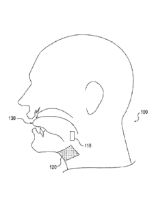
2
[004] Among the conditions to which neural modulation may be applied is
obstructive sleep apnea (OSA). OSA is a respiratory disorder characterized by
recurrent episodes of partial or complete obstruction of the upper airway
during
sleep. During the sleep of a person without OSA, the pharyngeal muscles relax
during sleep and gradually collapse, narrowing the airway. The airway
narrowing
limits the effectiveness of the sleeper's breathing, causing a rise in CO2
levels in the
blood. The increase in CO2 results in the pharyngeal muscles contracting to
open
the airway to restore proper breathing. The largest of the pharyngeal muscles
responsible for upper airway dilation is the genioglossus muscle, which is one
of
several different muscles in the tongue. The genioglossus muscle is
responsible for
forward tongue movement and the stiffening of the anterior pharyngeal wall, In
patients with OSA, the neuromuscular activity of the genioglossus muscle is
decreased compared to normal individuals, accounting for insufficient response
and
contraction to open the airway as compared to a normal individual. This lack
of
response contributes to a partial or total airway obstruction, which
significantly limits
the effectiveness of the sleeper's breathing. In OSA patients, there are often
several
airway obstruction events during the night. Because of the obstruction, there
is a
gradual decrease of oxygen levels in the blood (hypoxemia). Hypoxemia leads to
night time arousals, which may be registered by EEG, showing that the brain
awakes
from any stage of sleep to a short arousal. During the arousal, there is a
conscious
breath or gasp, which resolves the airway obstruction. An increase in
sympathetic
tone activity rate through the release of hormones such as epinephrine and
noradrenaline also often occurs as a response to hypoxemia. As a result of the
increase in sympathetic tone, the heart enlarges in an attempt to pump more
blood
and increase the blood pressure and heart rate, further arousing the patient.
After
the resolution of the apnea event, as the patient returns to sleep, the airway
collapses again, leading to further arousals.
[005] These repeated arousals, combined with repeated hypoxemia, leaves
the patient sleep deprived, which leads to daytime somnolence and worsens
cognitive function. This cycle can repeat itself up to hundreds of times per
night in
severe patients. Thus, the repeated fluctuations in and sympathetic tone and
episodes of elevated blood pressure during the night evolve to high blood
pressure
through the entire day. Subsequently, high blood pressure and increased heart
rate
may cause other diseases.
CA 02850434 2014-03-28
WO 2013/046032
PCT/IB2012/002357
3
[006] Efforts for treating OSA include Continuous Positive Airway Pressure
(CPAP) treatment, which requires the patient to wear a mask through which air
is
blown into the nostrils to keep the airway open. Other treatment options
include the
implantation of rigid inserts in the soft palate to provide structural
support,
tracheotomies, or tissue ablation.
[007] Another condition to which neural modulation may be applied is the
occurrence of migraine headaches. Pain sensation in the head is transmitted to
the
brain via the occipital nerve, specifically the greater occipital nerve, and
the
trigeminal nerve. When a subject experiences head pain , such as during a
migraine
headache, the inhibition of these nerves may serve to decrease or eliminate
the
sensation of pain.
[008] Neural modulation may also be applied to hypertension. Blood
pressure in the body is controlled via multiple feedback mechanisms. For
example,
baroreceptors in the carotid body in the carotid artery are sensitive to blood
pressure
changes within the carotid artery. The baroreceptors generate signals that are
conducted to the brain via the glossopharyngeal nerve when blood pressure
rises,
signaling the brain to activate the body's regulation system to lower blood
pressure,
e.g. through changes to heart rate, and vasodilation/vasoconstricfion.
Conversely,
parasympathetic nerve fibers on and around the renal arteries generate signals
that
are carried to the kidneys to initiate actions, such as salt retention and the
release of
angiotensin, which raise blood pressure. Modulating these nerves may provide
the
ability to exert some external control over blood pressure.
[009] At least some of the presently disclosed embodiments may include
methods of communicating between an implantable device, such as a neural
modulator, and an external unit configured to communicate with the implantable
device. In applications related to nerve modulation, such methods of
communication
may increase the efficiency of signal transmission between the implantable
device
and the external unit. Such methods of communication may also assist in other
applications; for example, where an implantable device may include a sensor to
sense one or more physiological conditions. For example, an implantable
glucose
sensor may monitor glucose levels of a subject, and, utilizing communication
methods disclosed herein, relay information about glucose levels to an
external
device.
CA 02850434 2014-03-28
WO 2013/046032 PCT/IB2012/002357
4
(010) The foregoing are just a few examples of conditions to which
neuromodulation may be of benefit, however embodiments of the invention
described hereafter are not necessarily limited to treating only the above-
described
conditions.
SUMMARY
[011] A device according to some disclosed embodiments may include an
external unit configured for location on a neck of a subject to communicate
with an
implant unit implanted proximal to a tongue of a subject. An indicator,
associated
with the external unit, may be configured to produce an indicator signal when
the
external unit is within a predetermined range of the implant unit. In
addition, the
indicator may be configured to vary the indicator signal according to a
distance
between the external unit and the implant unit.
[012] A device according to some disclosed embodiments may include an
external unit configured to communicate with an implant unit beneath the skin
of a
subject, an indicator associated with the external unit, and at least one
processor
configured to generate a primary signal on a primary antenna associated with
the
external unit. The primary signal being configured to cause a secondary signal
on a
secondary antenna associated with the implant unit. In addition, the processor
may
be configured to determine a degree of coupling between a primary antenna
associated with the external unit and a secondary antenna associated with the
implant unit and cause the indicator to produce a signal when the degree of
coupling
exceeds a predetermined threshold.
[0131 A device according to some disclosed embodiments may include an
external unit configured to communicate with an implant unit beneath the skin
of a
subject and an indicator associated with the external unit. The indicator
being
configured to produce an indicator signal when the external unit is within a
predetermined range of the implant unit and being configured to vary the
indicator
signal according to a distance between the external unit and the implant unit.
[014] A device according to some disclosed embodiments may include a
housing, configured for location on a subject to communicate with an implant
unit
implanted proximate to at least one of a renal nerve, a baroreceptor, and a
glossopharyngeal nerve, and an indicator associated with the housing. The
indicator
CA 02850434 2014-03-28
WO 2013/046032
PCT/IB2012/002357
may be configured to produce an indicator signal when the housing is within a
predetermined range of the implant unit. In addition, the indicator may be
configured
to vary the indicator signal according to a distance between the housing and
the
implant unit.
[015] A device according to some disclosed embodiments may include a
patch configured for placement on a side of hairline opposite a substantially
haired
region of a subject and an indicator associated with the patch. The indicator
may be
configured to produce an indicator signal when the patch is within a
predetermined
range of the implant unit. In addition, the indicator may be configured to
vary the
indicator signal according to a distance between the patch and the implant
unit.
[0161 The device may further include one or more of the following features:
the indicator signal may include a visual output, a tactile output, an audible
output, or
an electrical signal configured to communicate with the implant unit; the
electrical
signal may cause the implant unit to modulate a nerve and to induce at least
one of a
proprioceptive or kinesthesic reaction in the subject; the external unit may
comprise
at least one processor; the at least one processor being configured to:
generate a
primary signal on a primary antenna associated with the external unit, the
primary
signal being configured to cause a secondary signal on a secondary antenna
associated with the implant unit; determine a degree of coupling between the
primary
antenna associated with the external unit and the secondary antenna associated
with the implant unit; and cause the indicator to produce the indicator signal
when
the degree of coupling exceeds a predetermined threshold; determination of the
degree of coupling between the primary antenna associated with the external
unit
and the secondary antenna associated with the implant unit may be based, at
least
in part, on a measure of capacitive coupling, on a measure of radio frequency
coupling, on a measure of inductive coupling, or on an observation of non-
linear
behavior in a circuit associated with the implant unit; the observation of non-
linear
behavior may include at least one of observation of a transition from linear
behavior
to non-linear behavior or observation of non-linear harmonic behavior.
[017] In addition, the processor may further be configured to cause the
indicator to produce the indicator signal when the degree of coupling does not
exceed a predetermined threshold; the at least one processor may be configured
to
operate in a placement mode and a therapy mode, cause the indicator to produce
the variable signal during operation in the placement mode, and transition
from the
CA 02850434 2014-03-28
WO 2013/046032
PCT/IB2012/002357
6
placement mode to the therapy mode when a correct placement condition is
satisfied: the correct placement condition may include at least one of a
predetermined coupling threshold and a predetermined timing threshold, such
that
the predetermined timing threshold includes a pre-sleep waiting period. The
device
may further comprise a skin patch with an adhesive and configured for
adherence to
the skin of the subject, such that the external unit is removably connected to
the skin
patch, and such that the at least one processor is configured to operate in a
placement mode when the external unit is connected to the skin patch.
[018) A method of locating an external unit with respect to an implant unit
according to some disclosed embodiments may include the steps of detecting a
distance between the external unit and the implanted unit located beneath the
skin of
a subject, producing an indicator signal when the external unit is within a
predetermined range of the implant unit, and varying the indicator signal as a
function of a distance between the external unit and the implant unit.
10191 Additional features of the disclosure will be set forth in part in the
description that follows, and in part will be obvious from the description, or
may be
learned by practice of the disclosed embodiments.
[020] It is to be understood that both the foregoing general description and
the following detailed description are exemplary and explanatory only, and are
not
restrictive of the invention, as claimed.
BRIEF DESCRIPTION OF THE DRAWINGS
(021) The accompanying drawings, which are incorporated in and constitute
a part of this specification, illustrate several embodiments of the disclosure
and,
together with the description, serve to explain the principles of the
embodiments
disclosed herein.
[022] Figure 1 schematically illustrates an implant unit and external unit,
according to an exemplary embodiment of the present disclosure.
[023] Figure 2 is a partially cross-sectioned side view of a subject with an
implant unit and external unit, according to an exemplary embodiment of the
present
disclosure.
7
[024] Figure 3 schematically illustrates a system including an implant unit
and an external
unit, according to an exemplary embodiment of the present disclosure.
[025] Figure 4 is a top view of an implant unit, according to an exemplary
embodiment of the
present disclosure.
[026] Figure 5 is a top view of an alternate embodiment of an implant unit,
according to an
exemplary embodiment of the present disclosure.
[027] Figure 6 illustrates circuitry of an implant unit and an external unit,
according to an
exemplary embodiment of the present disclosure.
[028] Figure 7 illustrates a graph of quantities that may be used in
determining energy
delivery as a function coupling, according to an exemplary disclosed
embodiment.
[029] Figure 8 depicts a graph illustrating non-linear harmonics.
[030] Figure 9 depicts a graph of quantities that may be used in determining
energy delivery
as a function coupling, according to an exemplary disclosed embodiment.
[030A] Figure 10. depicts an exemplary implant location for the treatment of
sleep apnea.
[031] Figure 11 depicts an exemplary implant location for the treatment of
sleep apnea.
[032] Figure 12 depicts an exemplary implant location for the treatment of
head pain.
[033] Figure 13 depicts an exemplary implant location for the treatment of
hypertension.
[034] Figure 14 depicts an exemplary implant location for the treatment of
hypertension.
DESCRIPTION OF EXEMPLARY EMBODIMENTS
[035] Reference will now be made in detail to exemplary embodiments of the
present
disclosure, examples of which are illustrated in the accompanying drawings.
Wherever
possible, the same reference numbers will be used throughout the drawings to
refer to the
same or like parts.
[036] Embodiments of the present disclosure relate generally to a device for
modulating a
nerve through the delivery of energy. Nerve modulation, or neural modulation,
includes
inhibition (e.g. blockage), stimulation, modification, regulation,
Date Recue/Date Received 2020-07-10
CA 02850434 2014-03-28
WO 2013/046032
PCT/1132012/002357
8
or therapeutic alteration of activity, electrical or chemical, in the central,
peripheral, or
autonomic nervous system. Nerve modulation may take the form of nerve
stimulation, which may include providing energy to the nerve to create a
voltage
change sufficient for the nerve to activate, or propagate an electrical signal
of its
own. Nerve modulation may also take the form of nerve inhibition, which may
including providing energy to the nerve sufficient to prevent the nerve from
propagating electrical signals. Nerve inhibition may be performed through the
constant application of energy. and may also be performed through the
application of
enough energy to inhibit the function of the nerve for some time after the
application.
Other forms of neural modulation may modify the function of a nerve, causing a
heightened or lessened degree of sensitivity. As referred to herein,
modulation of a
nerve may include modulation of an entire nerve and/or modulation of a portion
of a
nerve. For example, modulation of a motor neuron may be performed to affect
only
those portions of the neuron that are distal of the location to which energy
is applied.
Furthermore, implant unit 110 may be configured to not perform any modulation
at
all. Implant unit 110 may be configured to measure physiological data, for
example
through sensors or other measuring devices. For example, implant unit 110 may
include sensors to detect a level of glucose in a subject, such information
may be
communicated to external unit 120 through various means as described herein.
[0371 In patients with OSA, for example, a primary target response of nerve
stimulation may include contraction of a tongue muscle (e.g., the muscle) in
order to
move the tongue to a position that does not block the patient's airway. In the
treatment of migraine headaches, nerve inhibition may be used to reduce or
eliminate the sensation of pain. In the treatment of hypertension, neural
modulation
may be used to increase, decrease, eliminate or otherwise modify nerve signals
generated by the body to regulate blood pressure.
[038] While embodiments of the present disclosure may be disclosed for use
in patients with specific conditions, the embodiments may be used in
conjunction
with any patient/portion of a body where nerve modulation may be desired. That
is,
in addition to use in patients with OSA, migraine headaches, or hypertension,
embodiments of the present disclosure may be use in many other areas,
including,
but not limited to: deep brain stimulation (e.g., treatment of epilepsy,
Parkinson's,
and depression); cardiac pace-making, stomach muscle stimulation (e.g.,
treatment
CA 02850434 2014-03-28
WO 2013/046032 PCT/IB2012/002357
9
of obesity), back pain, incontinence, menstrual pain, and/or any other
condition that
may be affected by neural modulation.
[039] Figure 1 illustrates an implant unit and external unit, according to an
exemplary embodiment of the present disclosure. An implant unit 110, may be
configured for implantation in a subject, in a location that permits it to
modulate a
nerve 115. The implant unit 110 may be located in a subject such that
intervening
tissue 111 exists between the implant unit 110 and the nerve 115. Intervening
tissue
may include muscle tissue, connective tissue, organ tissue, or any other type
of
biological tissue. Thus, location of implant unit 110 does not require contact
with
nerve 115 for effective neuromodulation. The implant unit 110 may also be
located
directly adjacent to nerve 115, such that no intervening tissue 111 exists.
[040] In treating OSA, implant unit 110 may be located on a genioglossus
muscle of a patient. Such a location is suitable for modulation of the
hypoglossal
nerve, branches of which run inside the genioglossus muscle. Further details
regarding implantation locations of an implant unit 110 for treatment of OSA
are
provided below with respect to Figs. 10 and 11. Implant unit 110 may also be
configured for placement in other locations. For example, migraine treatment
may
require subcutaneous implantation in the back of the neck, near the hairline
of a
subject, or behind the ear of a subject, to modulate the greater occipital
nerve, lesser
occipital nerve, and/or the trigeminal nerve. Further details regarding
implantation
locations of an implant unit 110 for treatment of head pain, such as migraine
headaches, are provided below with respect to Fig. 12. Treating hypertension
may
require the implantation of a neuromodulation implant intravascularly inside
the renal
artery or renal vein (to modulate the parasympathetic renal nerves), either
unilaterally or bilaterally, inside the carotid artery or jugular vein (to
modulate the
glossopharyngeal nerve through the carotid baroreceptors). Alternatively or
additionally, treating hypertension may require the implantation of a
neuromodulation
implant subcutaneously, behind the ear or in the neck, for example, to
directly
modulate the glossopharyngeal nerve. Further details regarding implantation
locations of an implant unit 110 for treatment of hypertension are provided
below,
with respect to Figs. 13 and 14.
[041] External unit 120 may be configured for location external to a patient,
either directly contacting, or close to the skin 112 of the patient. External
unit 120
may be configured to be affixed to the patient, for example, by adhering to
the skin
CA 02850434 2014-03-28
WO 2013/046032
PCT/IB2012/002357
112 of the patient, or through a band or other device configured to hold
external unit
120 in place. Adherence to the skin of external unit 120 may occur such that
it is in
the vicinity of the location of implant unit 110.
[042] Figure 2 illustrates an exemplary embodiment of a neuromodulation
system for delivering energy in a patient 100 with OSA. The system may include
an
external unit 120 that may be configured for location external to the patient.
As
illustrated in Figure 2, external unit 120 may be configured to be affixed to
the patient
100. Figure 2 illustrates that in a patient 100 with OSA, the external unit
120 may be
configured for placement underneath the patient's chin and/or on the front of
patient's neck. The suitability of placement locations may be determined by
communication between external unit 120 and implant unit 110, discussed in
greater
detail below. In alternate embodiments, for the treatment of conditions other
than
OSA, the external unit may be configured to be affixed anywhere suitable on a
patient, such as the back of a patient's neck, i.e. for communication with a
migraine
treatment implant unit, on the outer portion of a patient's abdomen, i.e. for
communication with a stomach modulating implant unit, on a patient's back,
i.e. for
communication with a renal artery modulating implant unit, and/or on any other
suitable external location on a patient's skin, depending on the requirements
of a
particular application.
[043] External unit 120 may further be configured to be affixed to an
alternative location proximate to the patient. For example, in one embodiment,
the
external unit may be configured to fixedly or removably adhere to a strap or a
band
that may be configured to wrap around a part of a patient's body.
Alternatively, or in
addition, the external unit may be configured to remain in a desired location
external
to the patient's body without adhering to that location.
[044] The external unit 120 may include a housing. The housing may include
any suitable container configured for retaining components. In addition, while
the
external unit is illustrated schematically in Fig. 2, the housing may be any
suitable
size and/or shape and may be rigid or flexible. Non-limiting examples of
housings
for the external unit 100 include one or more of patches, buttons, or other
receptacles having varying shapes and dimensions and constructed of any
suitable
material. In one embodiment, for example, the housing may include a flexible
material such that the external unit may be configured to conform to a desired
location. For example, as illustrated in Figure 2, the external unit may
include a skin
CA 02850434 2014-03-28
WO 2013/046032
PCT/IB2012/002357
11
patch, which, in turn, may include a flexible substrate. The material of the
flexible
substrate may include, but is not limited to, plastic, silicone, woven natural
fibers,
and other suitable polymers, copolymers, and combinations thereof. Any portion
of
external unit 120 may be flexible or rigid, depending on the requirements of a
particular application.
[045) As previously discussed, in some embodiments external unit 120 may
be configured to adhere to a desired location. Accordingly, in some
embodiments, at
least one side of the housing may include an adhesive material. The adhesive
material may include a blocompatible material and may allow for a patient to
adhere
the external unit to the desired location and remove the external unit upon
completion of use. The adhesive may be configured for single or multiple uses
of the
external unit. Suitable adhesive materials may include, but are not limited to
biocompatible glues, starches, elastomers, thermoplastics, and emulsions.
[046] Figure 3 schematically illustrates a system including external unit 120
and an implant unit 110. In some embodiments, internal unit 110 may be
configured
as a unit to be implanted into the body of a patient, and external unit 120
may be
configured to send signals to and/or receive signals from implant unit 110.
[0471 As shown in Figure 3, various components may be included within a
housing of external unit 120 or otherwise associated with external unit 120.
As
illustrated in Figure 3, at least one processor 144 may be associated with
external
unit 120. For example, the at least one processor 144 may be located within
the
housing of external unit 120. In alternative embodiments, the at least one
processor
may be configured for wired or wireless communication with the external unit
from a
location external to the housing.
[048] The at least one processor may include any electric circuit that may be
configured to perform a logic operation on at least one input variable. The at
least
one processor may therefore include one or more integrated circuits,
microchips,
microcontrollers, and microprocessors, which may be all or part of a central
processing unit (CPU), a digital signal processor (DSP), a field programmable
gate
array (FPGA), or any other circuit known to those skilled in the art that may
be
suitable for executing instructions or performing logic operations.
[049] Figure 3 illustrates that the external unit 120 may further be
associated
with a power source 140. The power source may be removably couplable to the
external unit at an exterior location relative to external unit.
Alternatively, as shown
CA 02850434 2014-03-28
WO 2013/046032
PCT/IB2012/002357
12
in Figure 3, power source 140 may be permanently or removably coupled to a
location within external unit 120. The power source may further include any
suitable
source of power configured to be in electrical communication with the
processor. In
one embodiment, for example the power source 140 may include a battery.
[050] The power source may be configured to power various components
within the external unit. As illustrated in Figure 3, power source 140 may be
configured to provide power to the processor 144. In addition, the power
source 140
may be configured to provide power to a signal source 142. The signal source
142
may be in communication with the processor 144 and may include any device
configured to generate a signal (e.g., a sinusoidal signal, square wave,
triangle
wave, microwave, radio-frequency (RF) signal, or any other type of
electromagnetic
signal). Signal source 142 may include, but is not limited to, a waveform
generator
that may be configured to generate alternating current (AC) signals and/or
direct
current (DC) signals. In one embodiment, for example, signal source 142 may be
configured to generate an AC signal for transmission to one or more other
components. Signal source 142 may be configured to generate a signal of any
suitable frequency. In some embodiments, signal source 142 may be configured
to
generate a signal having a frequency of from about 6.5 MHz to about 13.6 MHz.
In
additional embodiments, signal source 142 may be configured to generate a
signal
having a frequency of from about 7.4 to about 8.8 MHz. In further embodiments,
signal source 142 may generate a signal having a frequency as low as 90 kHz or
as
high as 28 MHz.
[051] Signal source 142 may be configured for direct or indirect electrical
communication with an amplifier 146. The amplifier may include any suitable
device
configured to amplify one or more signals generated from signal source 142.
Amplifier 146 may include one or more of various types of amplification
devices,
including, for example, transistor based devices, operational amplifiers, RF
amplifiers, power amplifiers, or any other type of device that can increase
the gain
associated one or more aspects of a signal. The amplifier may further be
configured
to output the amplified signals to one or more components within external unit
120.
[052] Figure 3 further illustrates that external unit 120 may be associated
with an indicator 145. That is, indicator 145 may be removably or permanently
attached to external unit 120. In one embodiment, for example, indicator 145
may
be located within external unit 120. Alternatively, indicator 145 may be in
wired or
CA 02850434 2014-03-28
WO 2013/046032 PCT/IB2012/002357
13
wireless communication with external unit 120 from a location external to
external
unit 120.
[053] The indicator 145 may include any suitable device configured to
provide a signal to the user and/ormay include any suitable signal output
elements
configured to communicate with a user. Suitable signal output elements may
include, but are not limited to, audible, visual, and tactile outputs. In one
embodiment, for example, the signal output means may include an electrical
signal
configured to communicate with the implant unit 110. That is, the electrical
signal
may cause the implant unit 110 to stimulate a nerve and/or induce one of a
proprioceptive or kinesthesic reaction in the user. Thus, in the context of an
implant
unit 110 located in the genioglosssus, processor 144 may be configured to
function
as the indicator 145 to cause a modulation of a nerve located within the
tongue by
the implant unit 110 (e.g.. the processor may provide the signal that causes a
physiological indication to the user). In other embodiments, the indicator 145
may be
configured to emit an audible signal, including one or more tones. The
indicator 145
may also or alternatively be configured with lighting elements (e.g., LEDs,
etc.) for
providing various visual signals to a user. Additionally or alternatively, the
indicator
145 may include a device configured to vibrate as part of an alert issued to
the user.
It should be understood that any combination of these or other suitable
signaling
elements may be included in the indicator 145 associated with external unit
120.
[054] The indicator 145 may further include any suitable antenna known to
those skilled in the art and may be configured to send and receive signals to
a user
in order to alert the user of a condition relating to the external unit 120
and/or implant
unit 110. In one embodiment, for example, the indicator 145 may be configured
to
provide a variable signal according to a distance between the external unit
120 and
the implant unit 110.
[055] The indicator 145 may be configured to permit a user to place the
external unit 120 at an optimal location in relation to the implant unit 110.
For
example, a user interested in placing external unit 120 on the skin, for
example, in
the vicinity of implant 110 may proceed to move external unit 120 around in
the
general vicinity of implant unit 110. When external unit 120 is placed in a
location
where a suitable connection can be achieved between external unit 120 and
implant
unit 110 (e.g., a suitable coupling connection), the indicator 145 may alert
the user of
this condition. The indicator 145 may further be configured to alert the user
of the
CA 02850434 2014-03-28
WO 2013/046032
PCT/IB2012/002357
14
degree of connectivity between external unit 120 and implant unit 110 such
that the
user may be able to place the external unit in a location where the connection
between the two units is at or near a maximum level.
[056] One or more functions associated with the indicator 145 may be
provided by a processor associated with external unit 120. For example, among
other functions, a processor may be configured to monitor a connection
strength
between external unit 120 and implant unit 110 and issue a control signal to
cause
the indicator 145 to activate.
[057] The external unit may additionally include a primary antenna 150. The
primary antenna may be configured as part of a circuit within external unit
120 and
may be coupled either directly or indirectly to various components in external
unit
120. For example, as shown in Figure 3, primary antenna 150 may be configured
for
communication with the amplifier 146.
[058] The primary antenna may include any conductive structure that may be
configured to create an electromagnetic field. The primary antenna may further
be of
any suitable size, shape, and/or configuration. The size, shape, and/or
configuration
may be determined by the size of the patient, the placement location of the
implant
unit, the size and/or shape of the implant unit, the amount of energy required
to
modulate a nerve, a location of a nerve to be modulated, the type of receiving
electronics present on the implant unit. etc. The primary antenna may include
any
suitable antenna known to those skilled in the art that may be configured to
send
and/or receive signals. Suitable antennas may include, but are not limited to,
a long-
wire antenna, a patch antenna, a helical antenna, etc. In one embodiment, for
example, as illustrated in Figure 3, primary antenna 150 may include a coil
antenna.
Such a coil antenna may be made from any suitable conductive material and may
be
configured to include any suitable arrangement of conductive coils (e.g.,
diameter,
number of coils, layout of coils, etc.). A coil antenna suitable for use as
primary
antenna 150 may have a diameter of between about 1 cm and 10 cm, and may be
circular or oval shaped. In some embodiments, a coil antenna may have a
diameter
between 5 cm and 7 cm, and may be oval shaped. A coil antenna suitable for use
as primary antenna 150 may have any number of windings, e.g. 4, 8, 12, or
more. A
coil antenna suitable for use as primary antenna 150 may have a wire diameter
between about 0.1 mm and 2 mm. These antenna parameters are exemplary only,
and may be adjusted above or below the ranges given to achieve suitable
results.
CA 02850434 2014-03-28
WO 2013/046032
PCT/IB2012/002357
[059] As noted, implant unit 110 may be configured to be implanted in a
patient's body (e.g., beneath the patient's skin). Figure 2 illustrates that
the implant
unit 110 may be configured to be implanted for modulation of a nerve
associated
with a muscle of the subject's tongue 130. Modulating a nerve associated with
a
muscle of the subject's tongue 130 may include stimulation to cause a muscle
contraction. In further embodiments, the implant unit may be configured to be
placed
in conjunction with any nerve that one may desire to modulate. For example,
modulation of the occipital nerve, the greater occipital nerve, and/or the
trigeminal
nerve may be useful for treating pain sensation in the head, such as that from
migraines. Modulation of parasympathetic nerve fibers on and around the renal
arteries (i.e.. the renal nerves), the vagus nerve, and /or the
glossopharyngeal nerve
may be useful for treating hypertension. Additionally, any nerve of the
peripheral
nervous system (both spinal and cranial), including motor neurons, sensory
neurons,
sympathetic neurons and parasympathetic neurons, may be modulated to achieve a
desired effect.
[0601 Implant unit 110 may be formed of any materials suitable for
implantation into the body of a patient. In some embodiments, implant unit 110
may
include a flexible carrier 161 (Figure 4) including a flexible, biocompatible
material.
Such materials may include, for example, silicone, polyimides,
phenyltrimethoxysilane (PTMS), polymethyl methacrylate (PMMA), Parylene C,
polyimide, liquid polyimide, laminated polyimide, black epoxy, polyether ether
ketone
(PEEK), Liquid Crystal Polymer (LCP), Kapton, etc. Implant unit 110 may
further
include circuitry including conductive materials, such as gold, platinum,
titanium, or
any other biocompatible conductive material or combination of materials.
Implant
unit 110 and flexible carrier 161 may also be fabricated with a thickness
suitable for
implantation under a patient's skin. Implant 110 may have thickness of less
than
about 4 mm or less than about 2 mm.
[061] Other components that may be included in or otherwise associated
with the implant unit are illustrated in Figure 3. For example, implant unit
110 may
include a secondary antenna 152 mounted onto or integrated with flexible
carrier
161. Similar to the primary antenna, the secondary antenna may include any
suitable antenna known to those skilled in the art that may be configured to
send
and/or receive signals. The secondary antenna may include any suitable size,
shape, and/or configuration. The size, shape and/or configuration may be
CA 02850434 2014-03-28
WO 2013/046032
PCT/IB2012/002357
16
determined by the size of the patient, the placement location of the implant
unit, the
amount of energy required to modulate the nerve, etc. Suitable antennas may
include, but are not limited to, a long-wire antenna, a patch antenna, a
helical
antenna, etc. In some embodiments, for example, secondary antenna 152 may
include a coil antenna having a circular shape (see also Figure 4) or oval
shape.
Such a coil antenna may be made from any suitable conductive material and may
be
configured to include any suitable arrangement of conductive coils (e.g.,
diameter,
number of coils, layout of coils, etc.). A coil antenna suitable for use as
secondary
antenna 152 may have a diameter of between about 5 mm and 30 mm, and may be
circular or oval shaped. A coil antenna suitable for use as secondary antenna
152
may have any number of windings, e.g. 4, 15, 20, 30, or 50. A coil antenna
suitable
for use as secondary antenna 152 may have a wire diameter between about 0.01
mm and 1 mm. These antenna parameters are exemplary only, and may be
adjusted above or below the ranges given to achieve suitable results.
[0521 Implant unit 110 may additionally include a plurality of field-
generating
implant electrodes 158a. 158b. The electrodes may include any suitable shape
and/or orientation on the implant unit so long as the electrodes may be
configured to
generate an electric field in the body of a patient. Implant electrodes 158a
and 158b
may also include any suitable conductive material (e.g., copper, silver, gold,
platinum, iridium, platinum-iridium, platinum-gold, conductive polymers, etc.)
or
combinations of conductive (and/or noble metals) materials. In some
embodiments,
for example, the electrodes may include short line electrodes, circular
electrodes,
and/or circular pairs of electrodes. As shown in Figure 4, electrodes 158a and
158b
may be located on an end of a first extension 162a of an elongate arm 162. The
electrodes, however, may be located on any portion of implant unit 110.
Additionally,
implant unit 110 may include electrodes located at a plurality of locations,
for
example on an end of both a first extension 162a and a second extension 162b
of
elongate arm 162, as illustrated, for example, in Figure 5. Implant electrodes
may
have a thickness between about 200 nanometers and 1 millimeter. Anode and
cathode electrode pairs may be spaced apart by about a distance of about 0.2
mm to
25 mm. In additional embodiments, anode and cathode electrode pairs may be
spaced apart by a distance of about 1 mm to 10 mm, or between 4 mm and 7 mm.
Adjacent anodes or adjacent cathodes may be spaced apart by distances as small
as 0.001 mm or less, or as great as 25 mm or more. In some embodiments,
CA 02850434 2014-03-28
WO 2013/046032
PCT/IB2012/002357
17
adjacent anodes or adjacent cathodes may be spaced apart by a distance between
about 0.2 mm and 1 mm.
(063] Figure 4 provides a schematic representation of an exemplary
configuration of implant unit 110. As illustrated in Figure 4, in one
embodiment, the
field-generating electrodes 158a and 158b may include two sets of four
circular
electrodes, provided on flexible carrier 161, with one set of electrodes
providing an
anode and the other set of electrodes providing a cathode. Implant unit 110
may
include one or more structural elements to facilitate implantation of implant
unit 110
into the body of a patient. Such elements may include, for example, elongated
arms,
suture holes, polymeric surgical mesh, biological glue, spikes of flexible
carrier
protruding to anchor to the tissue, spikes of additional biocompatible
material for the
same purpose, etc. that facilitate alignment of implant unit 110 in a desired
orientation within a patient's body and provide attachment points for securing
implant
unit 110 within a body. For example, in some embodiments, implant unit 110 may
include an elongate arm 162 having a first extension 162a and, optionally, a
second
extension 162b. Extensions 162a and 162b may aid in orienting implant unit 110
with respect to a particular muscle (e.g., the genioglossus muscle), a nerve
within a
patient's body, or a surface within a body above a nerve. For example, first
and
second extensions 162a, 162b may be configured to enable the implant unit to
conform at least partially around soft or hard tissue (e.g,, nerve, bone, or
muscle,
etc.) beneath a patient's skin. Further, implant unit 110 may also include one
or
more suture holes 160 located anywhere on flexible carrier 161. For example,
in
some embodiments, suture holes 160 may be placed on second extension 162b of
elongate arm 162 and/or on first extension 162a of elongate arm 162. Implant
unit
110 may be constructed in various shapes. In some embodiments, implant unit
may
appear substantially as illustrated in Figure 4. In other embodiments, implant
unit
110 may lack illustrated structures such as second extension 162b, or may have
additional or different structures in different orientations. Additionally,
implant unit
110 may be formed with a generally triangular, circular, or rectangular shape,
as an
alternative to the winged shape shown in Figure 4. In some embodiments, the
shape of implant unit 110 (e.g., as shown in Figure 4) may facilitate
orientation of
implant unit 110 with respect to a particular nerve to be modulated. Thus,
other
regular or irregular shapes may be adopted in order to facilitate implantation
in
differing parts of the body.
CA 02850434 2014-03-28
WO 2013/046032 PCT/I132012/002357
18
[064] As illustrated in Figure 4, secondary antenna 152 and electrodes
158a, 158b may be mounted on or integrated with flexible carrier 161. Various
circuit components and connecting wires (discussed further below) may be used
to
connect secondary antenna with implant electrodes 158a and 158b. To protect
the
antenna, electrodes, circuit components, and connecting wires from the
environment
within a patient's body, implant unit 110 may include a protective coating
that
encapsulates implant unit 110. In some embodiments, the protective coating may
be
made from a flexible material to enable bending along with flexible carrier
161. The
encapsulation material of the protective coating may also resist humidity
penetration
and protect against corrosion. In some embodiments, the protective coating may
include silicone, polyimides, phenyltrimethoxysilane (PTMS), polymethyl
methacrylate (PMMA), Parylene C, liquid polyimide, laminated polyimide,
polyimide,
Kapton, black epoxy, polyether ketone (PEEK), Liquid Crystal Polymer (LCP), or
any
other suitable biocompatible coating. In some embodiments, the protective
coating
may include a plurality of layers, including different materials or
combinations of
materials in different layers.
[065] Figure 5 is a perspective view of an alternate embodiment of an
implant unit 110, according to an exemplary embodiment of the present
disclosure.
As illustrated in Figure 5, implant unit 110 may include a plurality of
electrodes,
located, for example, at the ends of first extension 162a and second extension
162b.
Figure 5 illustrates an embodiment wherein implant electrodes 158a and 158b
include short line electrodes.
[066] Returning to Figures 2 and 3, external unit 120 may be configured to
communicate with implant unit 110. For example, in some embodiments, a primary
signal may be generated on primary antenna 150, using, e.g., processor 144,
signal
source 142, and amplifier 146. More specifically, in one embodiment, power
source
140 may be configured to provide power to one or both of the processor 144 and
the
signal source 142. The processor 144 may be configured to cause signal source
142 to generate a signal (e.g., an RF energy signal). Signal source 142 may be
configured to output the generated signal to amplifier 146, which may amplify
the
signal generated by signal source 142. The amount of amplification and,
therefore,
the amplitude of the signal may be controlled, for example, by processor 144.
The
amount of gain or amplification that processor 144 causes amplifier 146 to
apply to
the signal may depend on a variety of factors, including, but not limited to,
the shape,
CA 02850434 2014-03-28
WO 2013/046032
PCT/IB2012/002357
19
size, and/or configuration of primary antenna 150, the size of the patient,
the location
of implant unit 110 in the patient, the shape, size, and/or configuration of
secondary
antenna 152, a degree of coupling between primary antenna 150 and secondary
antenna 152 (discussed further below), a desired magnitude of electric field
to be
generated by implant electrodes 158a, 158b, etc. Amplifier 146 may output the
amplified signal to primary antenna 150.
(067] External unit 120 may communicate a primary signal on primary
antenna to the secondary antenna 152 of implant unit 110. This communication
may
result from coupling between primary antenna 150 and secondary antenna 152.
Such coupling of the primary antenna and the secondary antenna may include any
interaction between the primary antenna and the secondary antenna that causes
a
signal on the secondary antenna in response to a signal applied to the primary
antenna. In some embodiments, coupling between the primary and secondary
antennas may include capacitive coupling, inductive coupling, radiofrequency
coupling, etc. and any combinations thereof.
[068] Coupling between primary antenna 150 and secondary antenna 152
may depend on the proximity of the primary antenna relative to the secondary
antenna. That is, in some embodiments, an efficiency or degree of coupling
between primary antenna 150 and secondary antenna 152 may depend on the
proximity of the primary antenna to the secondary antenna. The proximity of
the
primary and secondary antennas may be expressed in terms of a coaxial offset
(e.g.,
a distance between the primary and secondary antennas when central axes of the
primary and secondary antennas are co-aligned),a lateral offset (e.g., a
distance
between a central axis of the primary antenna and a central axis of the
secondary
antenna), and/or an angular offset (e.g., an angular difference between the
central
axes of the primary and secondary antennas). In some embodiments, a
theoretical
maximum efficiency of coupling may exist between primary antenna 150 and
secondary antenna 152 when both the coaxial offset, the lateral offset, and
the
angular offset are zero. Increasing any of the coaxial offset, the lateral
offset, and
the angular offset may have the effect of reducing the efficiency or degree of
coupling between primary antenna 150 and secondary antenna 152.
[0691 As a result of coupling between primary antenna 150 and secondary
antenna 152, a secondary signal may arise on secondary antenna 152 when the
primary signal is present on the primary antenna 150. Such coupling may
include
CA 02850434 2014-03-28
WO 2013/046032
PCT/IB2012/002357
inductive/magnetic coupling, RF coupling/transmission, capacitive coupling, or
any
other mechanism where a secondary signal may be generated on secondary
antenna 152 in response to a primary signal generated on primary antenna 150.
Coupling may refer to any interaction between the primary and secondary
antennas.
In addition to the coupling between primary antenna 150 and secondary antenna
152, circuit components associated with implant unit 110 may also affect the
secondary signal on secondary antenna 152. Thus, the secondary signal on
secondary antenna 152 may refer to any and all signals and signal components
present on secondary antenna 152 regardless of the source.
[070] While the presence of a primary signal on primary antenna 150 may
cause or induce a secondary signal on secondary antenna 152, the coupling
between the two antennas may also lead to a coupled signal or signal
components
on the primary antenna 150 as a result of the secondary signal present on
secondary
antenna 152. A signal on primary antenna 150 induced by a secondary signal on
secondary antenna 152 may be referred to as a primary coupled signal
component.
The primary signal may refer to any and all signals or signal components
present on
primary antenna 150. regardless of source, and the primary coupled signal
component may refer to any signal or signal component arising on the primary
antenna as a result of coupling with signals present on secondary antenna 152.
Thus, in some embodiments, the primary coupled signal component may contribute
to the primary signal on primary antenna 150.
[071] Implant unit 110 may be configured to respond to external unit 120.
For example, in some embodiments, a primary signal generated on primary coil
150
may cause a secondary signal on secondary antenna 152, which in turn, may
cause
one or more responses by implant unit 110. In some embodiments, the response
of
implant unit 110 may include the generation of an electric field between
implant
electrodes 158a and 158b.
[072] Figure 6 illustrates circuitry 170 that may be included in external unit
120 and circuitry 180 that may be included in implant unit 110. Additional,
different,
or fewer circuit components may be included in either or both of circuitry 170
and
circuitry 180. As shown in Figure 6, secondary antenna 152 may be arranged in
electrical communication with implant electrodes 158a, 158b. In some
embodiments, circuitry connecting secondary antenna 152 with implant
electrodes
158a and 158b may cause a voltage potential across implant electrodes 158a and
CA 02850434 2014-03-28
WO 2013/046032 PCT/IB2012/002357
21
158b in the presence of a secondary signal on secondary antenna 152. This
voltage
potential may be referred to as a field inducing signal, as this voltage
potential may
generate an electric field between implant electrodes 158a and 158b. More
broadly,
the field inducing signal may include any signal (e.g., voltage potential)
applied to
electrodes associated with the implant unit that may result in an electric
field being
generated between the electrodes.
[073] The field inducing signal may be generated as a result of conditioning
of the secondary signal by circuitry 180. As shown in Figure 6, circuitry 170
of
external unit 120 may be configured to generate an AC primary signal on
primary
antenna 150 that may cause an AC secondary signal on secondary antenna 152. In
certain embodiments, however, it may be advantageous (e.g., in order to
generate a
unidirectional electric field for modulation of a nerve) to provide a DC field
inducing
signal at implant electrodes 158a and 158b. To convert the AC secondary signal
on
secondary antenna 152 to a DC field inducing signal, circuitry 180 in implant
unit 110
may include an AC-DC converter. The AC to DC converter may include any
suitable
converter known to those skilled in the art For example, in some embodiments
the
AC-DC converter may include rectification circuit components including, for
example,
diode 156 and appropriate capacitors and resistors. In alternative
embodiments,
implant unit 110 may include an AC-AC converter, or no converter, in order to
provide an AC field inducing signal at implant electrodes 158a and 158b.
[074] As noted above, the field inducing signal may be configured to
generate an electric field between implant electrodes 158a and 158b. In some
instances, the magnitude and/or duration of the generated electric field
resulting from
the field inducing signal may be sufficient to modulate one or more nerves in
the
vicinity of electrodes 158a and 158b. In such cases, the field inducing signal
may be
referred to as a modulation signal. In other instances, the magnitude and/or
duration
of the field inducing signal may generate an electric field that does not
result in nerve
modulation. In such cases, the field inducing signal may be referred to as a
sub-
modulation signal.
[075] Various types of field inducing signals may constitute modulation
signals. For example, in some embodiments, a modulation signal may include a
moderate amplitude and moderate duration, while in other embodiments, a
modulation signal may include a higher amplitude and a shorter duration.
Various
amplitudes and/or durations of field-inducing signals across electrodes 158a,
158b
CA 02850434 2014-03-28
WO 2013/046032 PCT/IB2012/002357
22
may result in modulation signals, and whether a field-inducing signal rises to
the
level of a modulation signal can depend on many factors (e.g., distance from a
particular nerve to be stimulated; whether the nerve is branched; orientation
of the
induced electric field with respect to the nerve; type of tissue present
between the
electrodes and the nerve; etc.).
[076] Whether a field inducing signal constitutes a modulation signal
(resulting in an electric field that may cause nerve modulation) or a sub-
modulation
signal (resulting in an electric field not intended to cause nerve modulation)
may
ultimately be controlled by processor 144 of external unit 120. For example,
in
certain situations, processor 144 may determine that nerve modulation is
appropriate. Under these conditions, processor 144 may cause signal source 144
and amplifier 146 to generate a modulation control signal on primary antenna
150
(i.e., a signal having a magnitude and/or duration selected such that a
resulting
secondary signal on secondary antenna 152 will provide a modulation signal at
implant electrodes 158a and 158b).
[077] Processor 144 may be configured to limit an amount of energy
transferred from external unit 120 to implant unit 110. For example, in some
embodiments, implant unit 110 may be associated with a threshold energy limit
that
may take into account multiple factors associated with the patient and/or the
implant.
For example, in some cases, certain nerves of a patient should receive no more
than
a predetermined maximum amount of energy to minimize the risk of damaging the
nerves and/or surrounding tissue. Additionally, circuitry 180 of implant unit
110 may
include components having a maximum operating voltage or power level that may
contribute to a practical threshold energy limit of implant unit 110. For
example,
components including diodes may be included in implant unit 110 or in external
unit
120 to limit power transferred from the external unit 120 to the implant unit
110. In
some embodiments, diode 156 may function to limit the power level received by
the
patient. Processor 144 may be configured to account for such limitations when
setting the magnitude and/or duration of a primary signal to be applied to
primary
antenna 150.
[0781 In addition to determining an upper limit of power that may be delivered
to implant unit 110, processor 144 may also determine a lower power threshold
based, at least in part, on an efficacy of the delivered power. The lower
power
threshold may be computed based on a minimum amount of power that enables
CA 02850434 2014-03-28
WO 2013/046032
PCT/IB2012/002357
23
nerve modulation (e.g., signals having power levels above the lower power
threshold
may constitute modulation signals while signals having power levels below the
lower
power threshold may constitute sub-modulation signals).
[079] A lower power threshold may also be measured or provided in
alternative ways. For example, appropriate circuitry or sensors in the implant
unit
110 may measure a lower power threshold. A lower power threshold may be
computed or sensed by an additional external device, and subsequently
programmed into processor 144, or programmed into implant unit 110.
Alternatively,
implant unit 110 may be constructed with circuitry 180 specifically chosen to
generate signals at the electrodes of at least the lower power threshold. In
still
another embodiment, an antenna of external unit 120 may be adjusted to
accommodate or produce a signal corresponding to a specific lower power
threshold.
The lower power threshold may vary from patient to patient, and may take into
account multiple factors, such as, for example, modulation characteristics of
a
particular patient's nerve fibers, a distance between implant unit 110 and
external
unit 120 after implantation, and the size and configuration of implant unit
components (e.g., antenna and implant electrodes), etc.
[080] Processor 144 may also be configured to cause application of sub-
modulation control signals to primary antenna 150. Such sub-modulation control
signals may include an amplitude and/or duration that result in a sub-
modulation
signal at electrodes 158a, 158b. While such sub-modulation control signals may
not
result in nerve modulation, such sub-modulation control signals may enable
feedback-based control of the nerve modulation system. That is, in some
embodiments, processor 144 may be configured to cause application of a sub-
modulation control signal to primary antenna 150. This signal may induce a
secondary signal on secondary antenna 152, which, in turn, induces a primary
coupled signal component on primary antenna 150.
[081] To analyze the primary coupled signal component induced on primary
antenna 150, external unit 120 may include a feedback circuit 148 (e.g., a
signal
analyzer or detector, etc.), which may be placed in direct or indirect
communication
with primary antenna 150 and processor 144. Sub-modulation control signals may
be applied to primary antenna 150 at any desired periodicity. In some
embodiments,
the sub-modulation control signals may be applied to primary antenna 150 at a
rate
of one every five seconds (or longer). In other embodiments, the sub-
modulation
CA 02850434 2014-03-28
WO 2013/046032 PCT/IB2012/002357
24
control signals may be applied more frequently (e.g., once every two seconds,
once
per second, once per millisecond, once per nanosecond, or multiple times per
second). Further, it should be noted that feedback may also be received upon
application of modulation control signals to primary antenna 150 (i.e., those
that
result in nerve modulation), as such modulation control signals may also
result in
generation of a primary coupled signal component on primary antenna 150.
[082] The primary coupled signal component may be fed to processor 144 by
feedback circuit 148 and may be used as a basis for determining a degree of
coupling between primary antenna 150 and secondary antenna 152. The degree of
coupling may enable determination of the efficacy of the energy transfer
between
two antennas. Processor 144 may also use the determined degree of coupling in
regulating delivery of power to implant unit 110.
[083] Processor 144 may be configured with any suitable logic for
determining how to regulate power transfer to implant unit 110 based on the
determined degree of coupling. Processor 144 may, for example, utilize a
baseline
coupling range. Presumably, while the patient is awake, the tongue is not
blocking
the patient's airway and moves with the patient's breathing in a natural
range, where
coupling between primary antenna 150 and secondary antenna 152 may be within a
baseline coupling range. A baseline coupling range may encompass a maximum
coupling between primary antenna 150 and secondary antenna 152. A baseline
coupling range may also encompass a range that does not include a maximum
coupling level between primary antenna 150 and secondary antenna 152.
Processor
144 may be configured to determine the baseline coupling range based on a
command from a user, such as the press of a button on the patch or the press
of a
button on a suitable remote device. Alternatively or additionally, processor
144 may
be configured to automatically determine the baseline coupling range when
external
unit 120 is placed such that primary antenna 150 and secondary antenna 152 are
within range of each other. In such an embodiment, when processor 144 detects
any degree of coupling between primary antenna 150 and secondary antenna 152,
it
may immediately begin tracking a baseline coupling range. Processor 144 may
then
determine a baseline coupling range when it detects that the only movement
between primary antenna 150 and secondary antenna 152 is caused by a patient's
natural breathing rhythm (i.e., the patient has secured the external unit to
an
appropriate location on their body). Additionally, processor 144 may be
configured
CA 02850434 2014-03-28
WO 2013/046032 PCT/IB2012/002357
such that it measures coupling between the primary antenna 150 and the
secondary
antenna 152 for a specified period of time after activation in order to
determine a
baseline coupling range, such as 1 minute, 5 minutes, 10 minutes, etc.
[084] Where the primary coupled signal component indicates that a degree
of coupling has changed from a baseline coupling range, processor 144 may
determine that secondary antenna 152 has moved with respect to primary antenna
150 (either in coaxial offset, lateral offset, or angular offset, or any
combination).
Such movement, for example, may be associated with a movement of the implant
unit 110, and the tissue that it is associated with based on its implant
location. Thus,
in such situations, processor 144 may determine that modulation of a nerve in
the
patient's body is appropriate. More particularly, in response to an indication
of a
change in coupling, processor 144, in some embodiments, may cause application
of
a modulation control signal to primary antenna 150 in order to generate a
modulation
signal at implant electrodes 158a, 158b, e.g., to cause modulation of a nerve
of the
patient.
[085] In an embodiment for the treatment of OSA, movement of an implant
unit 110 may be associated with movement of the tongue, which may indicate the
onset of a sleep apnea event or a sleep apnea precursor. The onset of a sleep
apnea event of sleep apnea precursor may require the stimulation of the
genioglossus muscle of the patient to relieve or avert the event. Such
stimulation
may result in contraction of the muscle and movement of the patient's tongue
away
from the patient's airway.
[086] In embodiments for the treatment of head pain, including migraines,
processor 144 may be configured to generate a modulation control signal based
on a
signal from a user, for example, or a detected level of neural activity in a
sensory
neuron (e.g. the greater occipital nerve or trigeminal nerve) associated with
head
pain. A modulation control signal generated by the processor and applied to
the
primary antenna 150 may generate a modulation signal at implant electrodes
158a,
.158b, e.g., to cause inhibition or blocking (i.e. a down modulation) of a
sensory nerve
of the patient. Such inhibition or blocking may decrease or eliminate the
sensation of
pain for the patient.
[087] In embodiments for the treatment of hypertension, processor 144 may
be configured to generate a modulation control signal based on, for example,
pre-
programmed instructions and/or signals from an implant indicative of blood
pressure.
CA 02850434 2014-03-28
WO 2013/046032
PCT/IB2012/002357
26
A modulation control signal generated by the processor and applied to the
primary
antenna 150 may generate a modulation signal at implant electrodes 158a, 158b,
e.g., to cause either inhibition or stimulation of nerve of a patient,
depending on the
requirements. For example, a neuromodulator placed in a carotid artery or
jugular
vein(i.e. in the vicinity of a carotid baroreceptor), may receive a modulation
control
signal tailored to induce a stimulation signal at the electrodes, thereby
causing the
glossopharyngeal nerve associated with the carotid baroreceptors to fire at an
increased rate in order to signal the brain to lower blood pressure. Similar
modulation of the glossopharyngeal nerve may be achieved with a neuromodulator
implanted in a subcutaneous location in a patient's neck or behind a patient's
ear. A
neuromodulator place in a renal artery may receive a modulation control signal
tailored to cause an inhibiting or blocking signal (i.e. a down modulation) at
the
electrodes, thereby inhibiting a signal to raise blood pressure carried from
the renal
nerves to the kidneys.
[088] Modulation control signals may include stimulation control signals, and
sub-modulation control signals may include sub-stimulation control signals.
Stimulation control signals may have any amplitude, pulse duration, or
frequency
combination that results in a stimulation signal at electrodes 158a, 158b. In
some
embodiments (e.g., at a frequency of between about 6.5-13.6 MHz), stimulation
control signals may include a pulse duration of greater than about 50
microseconds
and/or an amplitude of approximately .5 amps, or between 0.1 amps and 1 amp,
or
between 0.05 amps and 3 amps. Sub-stimulation control signals may have a pulse
duration less than about 500, or less than about 200 nanoseconds and/or an
amplitude less than about 1 amp, 0.5 amps, 0.1 amps, 0.05 amps, or 0.01 amps.
Of
course, these values are meant to provide a general reference only, as various
combinations of values higher than or lower than the exemplary guidelines
provided
may or may not result in nerve stimulation.
[089) In some embodiments, stimulation control signals may include a pulse
train, wherein each pulse includes a plurality of sub-pulses. An alternating
current
signal (e.g., at a frequency of between about 6.5-13.6 MHz) may be used to
generate the pulse train, as follows. A sub-pulse may have a duration of
between
50-250 microseconds, or a duration of between 1 microsecond and 2
milliseconds,
during which an alternating current signal is turned on. For example, a 200
microsecond sub-pulse of a 10 MHz alternating current signal will include
CA 02850434 2014-03-28
WO 2013/046032
PCT/IB2012/002357
27
approximately 2000 periods. Each pulse may, in turn, have a duration of
between
100 and 500 milliseconds, during which sub-pulses occur at a frequency of
between
25 and 100 Hz. For example, a 200 millisecond pulse of 50 Hz sub-pulses will
include approximately 10 sub-pulses. Finally, in a pulse train, each pulse may
be
separated from the next by a duration of between 0.2 and 2 seconds. For
example,
in a pulse train of 200 millisecond pulses, each separated by 1.3 seconds from
the
next, a new pulse will occur every 1.5 seconds. A pulse train of this
embodiment
may be utilized, for example, to provide ongoing stimulation during a
treatment
session. In the context of OSA, a treatment session may be a period of time
during
which a subject is asleep and in need of treatment to prevent OSA. Such a
treatment session may last anywhere from about three to ten hours. In the
context
of other conditions to which neural modulators of the present disclosure are
applied,
a treatment session may be of varying length according to the duration of the
treated
condition.
[090] Processor 144 may be configured to determine a degree of coupling
between primary antenna 150 and secondary antenna 152 by monitoring one or
more aspects of the primary coupled signal component received through feedback
circuit 148. In some embodiments, processor 144 may determine a degree of
coupling between primary antenna 150 and secondary antenna 152 by monitoring a
voltage level associated with the primary coupled signal component, a current
level,
or any other attribute that may depend on the degree of coupling between
primary
antenna 150 and secondary antenna 152. For example, in response to periodic
sub-
modulation signals applied to primary antenna 150, processor 144 may determine
a
baseline voltage level or current level associated with the primary coupled
signal
component. This baseline voltage level, for example, may be associated with a
range of movement of the patient's tongue when a sleep apnea event or its
precursor is not occurring, e.g. during normal breathing. As the patient's
tongue
moves toward a position associated with a sleep apnea event, moves in a manner
consistent with a precursor of sleep apnea, or moves in any other manner
(e.g.,
vibration, etc.), the coaxial, lateral, or angular offset between primary
antenna 150
and secondary antenna 152 may change. As a result, the degree of coupling
between primary antenna 150 and secondary antenna 152 may change, and the
voltage level or current level of the primary coupled signal component on
primary
antenna 150 may also change. Processor 144 may be configured to recognize a
CA 02850434 2014-03-28
WO 2013/046032 PCT/IB2012/002357
28
sleep apnea event or its precursor when a voltage level, current level, or
other
electrical characteristic associated with the primary coupled signal component
changes by a predetermined amount or reaches a predetermined absolute value.
[0911 Figure 7 provides a graph that illustrates this principle in more
detail.
For a two-coil system where one coil receives a radio frequency (RF) drive
signal,
graph 200 plots a rate of change in induced current in the receiving coil as a
function
of coaxial distance between the coils. For various coil diameters and initial
displacements, graph 200 illustrates the sensitivity of the induced current to
further
displacement between the coils, moving them either closer together or further
apart.
It also indicates that, overall, the induced current in the secondary coil
will decrease
as the secondary coil is moved away from the primary, drive coil, i.e. the
rate of
change of induced current, in mA/mm, is consistently negative. The sensitivity
of the
induced current to further displacement between the coils varies with
distance. For
example, at a separation distance of 10 mm, the rate of change in current as a
function of additional displacement in a 14 mm coil is approximately -6 mA/mm.
If
the displacement of the coils is approximately 22 mm, the rate of change in
the
induced current in response to additional displacement is approximately -11
mA/mm,
which corresponds to a local maximum in the rate of change of the induced
current.
Increasing the separation distance beyond 22 mm continues to result in a
decline in
the induced current in the secondary coil, but the rate of change decreases.
For
example, at a separation distance of about 30 mm, the 14 mm coil experiences a
rate of change in the induced current in response to additional displacement
of about
-8 mA/mm. With this type of information, processor 144 may be able to
determine a
particular degree of coupling between primary antenna 150 and secondary
antenna
152, at any given time, by observing the magnitude and/or rate of change in
the
magnitude of the current associated with the primary coupled signal component
on
primary antenna 150.
[0921 Processor 144 may be configured to determine a degree of coupling
between primary antenna 150 and secondary antenna 152 by monitoring other
aspects of the primary coupled signal component. For example, in some
embodiments, the non-linear behavior of circuitry 180 in implant unit 110 may
be
monitored to determine a degree of coupling. For example, the presence,
absence,
magnitude, reduction and/or onset of harmonic components in the primary
coupled
signal component on primary antenna 150 may reflect the behavior of circuitry
180 in
CA 02850434 2014-03-28
WO 2013/046032
PCT/IB2012/002357
29
response to various control signals (either sub-modulation or modulation
control
signals) and, therefore, may be used to determine a degree of coupling between
primary antenna 150 and secondary antenna 152.
[093] As shown in Figure 6, circuitry 180 in implant unit 110 may constitute a
non-linear circuit due, for example, to the presence of non-linear circuit
components,
such as diode 156. Such non-linear circuit components may induce non-linear
voltage responses under certain operation conditions. Non-linear operation
conditions may be induced when the voltage potential across diode 156 exceeds
the
activation threshold for diode 156. Thus, when implant circuitry 180 is
excited at a
particular frequency, this circuit may oscillate at multiple frequencies.
Spectrum
analysis of the secondary signal on secondary antenna 152, therefore, may
reveal
one or more oscillations, called harmonics, that appear at certain multiples
of the
excitation frequency. Through coupling of primary antenna 150 and secondary
antenna 152, any harmonics produced by implant circuitry 180 and appearing on
secondary antenna 152 may also appear in the primary coupled signal component
present on primary antenna 150.
10941 In certain embodiments, circuitry 180 may include additional circuit
components that alter the characteristics of the harmonics generated in
circuitry 180
above a certain transition point. Monitoring how these non-linear harmonics
behave
above and below the transition point may enable a determination of a degree of
coupling between primary antenna 150 and secondary antenna 152. For example,
as shown in Figure 6, circuitry 180 may include a harmonics modifier circuit
154,
which may include any electrical components that non-linearly alter the
harmonics
generated in circuitry 180. In some embodiments, harmonics modifier circuit
154
may include a pair of Zener diodes. Below a certain voltage level, these Zener
diodes remain forward biased such that no current will flow through either
diode.
Above the breakdown voltage of the Zener diodes, however, these devices become
conductive in the reversed biased direction and will allow current to flow
through
harmonics modifier circuit 154. Once the Zener diodes become conductive, they
begin to affect the oscillatory behavior of circuitry 180, and, as a result,
certain
harmonic oscillation frequencies may be affected (e.g., reduced in magnitude).
(095] Figures 8 and 9 illustrate this effect. For example, Figure 8
illustrates a
graph 300a that shows the oscillatory behavior of circuitry 180 at several
amplitudes
ranging from about 10 nanoamps to about 20 microamps. As shown, the primary
CA 02850434 2014-03-28
WO 2013/046032 PCT/IB2012/002357
excitation frequency occurs at about 6.7 MHz and harmonics appear both at even
and odd multiples of the primary excitation frequency. For example, even
multiples
appear at twice the excitation frequency (peak 302a), four times the
excitation
frequency (peak 304a) and six times the excitation frequency (peak 306a). As
the
amplitude of the excitation signal rises between 10 nanoamps and 40 microamps,
the amplIude of peaks 302a, 304a, and 306a all increase.
[096] Figure 9 illustrates the effect on the even harmonic response of
circuitry 180 caused by harmonics modifier circuit 154. Figure 9 illustrates a
graph
300b that shows the oscillatory behavior of circuitry 180 at several
amplitudes
ranging from about 30 microamps to about 100 microamps. As in Figure 8, Figure
9
shows a primary excitation frequency at about 6.7 MHz and second, fourth, and
sixth
order harmonics (peaks 302b, 304b, and 306b, respectively) appearing at even
multiples of the excitation frequency. As the amplitude of the excitation
signal rises,
however between about 30 microamps to about 100 microamps, the amplitudes of
peaks 302b, 304b, and 306b do not continuously increase. Rather, the amplitude
of
the second order harmonics decreases rapidly above a certain transition level
(e.g.,
about 80 microamps in Figure 8). This transition level corresponds to the
level at
which the Zener diodes become conductive in the reverse biased direction and
begin
to affect the oscillator/ behavior of circuitry 180.
[097] Monitoring the level at which this transition occurs may enable a
determination of a degree of coupling between primary antenna 150 and
secondary
antenna 152. For example, in some embodiments, a patient may attach external
unit
120 over an area of the skin under which implant unit 110 resides. Processor
144
can proceed to cause a series of sub-modulation control signals to be applied
to
primary antenna 150, which in turn cause secondary signals on secondary
antenna
152. These sub-modulation control signals may progress over a sweep or scan of
various signal amplitude levels. By monitoring the resulting primary coupled
signal
component on primary antenna 150 (generated through coupling with the
secondary
signal on secondary antenna 152), processor 144 can determine the amplitude of
primary signal (whether a sub-modulation control signal or other signal) that
results
in a secondary signal of sufficient magnitude to activate harmonics modifier
circuit
154. That is, processor 144 can monitor the amplitude of the second, fourth,
or sixth
order harmonics and determine the amplitude of the primary signal at which the
amplitude of any of the even harmonics drops. Figures 8 and 9 illustrate the
CA 02850434 2014-03-28
WO 2013/046032
PCT/IB2012/002357
31
principles of detecting coupling through the measurement of non-linear
harmonics.
These Figures illustrate data based around a 6.7 MHz excitation frequency.
These
principles, however, are not limited to the 6.7 MHz excitation frequency
illustrated,
and may be used with a primary signal of any suitable frequency.
[098] In embodiments utilizing non-linear harmonics, the determined
amplitude of the primary signal corresponding to the transition level of the
Zener
diodes (which may be referred to as a primary signal transition amplitude) may
establish the baseline coupling range when the patient attaches external unit
120 to
the skin. Thus, the initially determined primary signal transition amplitude
may be
fairly representative of a non-sleep apnea condition and may be used by
processor
144 as a baseline in determining a degree of coupling between primary antenna
150
and secondary antenna 152. Optionally, processor 144 may also be configured to
monitor the primary signal transition amplitude over a series of scans and
select the
minimum value as a baseline, as the minimum value may correspond to a
condition
of maximum coupling between primary antenna 150 and secondary antenna 152
during normal breathing conditions.
[099] As the patient wears external unit 120, processor 144 may periodically
scan over a range of primary signal amplitudes to determine a current value of
the
primary signal transition amplitude. In some embodiments, the range of
amplitudes
that processor 144 selects for the scan may be based on (e.g., near) the level
of the
baseline primary signal transition amplitude. If a periodic scan results in
determination of a primary signal transition amplitude different from the
baseline
primary signal transition amplitude, processor 144 may determine that there
has
been a change from the baseline initial conditions. For example, in some
embodiments, an increase in the primary signal transition amplitude over the
baseline value may indicate that there has been a reduction in the degree of
coupling between primary antenna 150 and secondary antenna 152 (e.g., because
the implant has moved or an internal state of the implant has changed).
[0100] In addition to determining whether a change in the degree of coupling
has occurred, processor 144 may also be configured to determine a specific
degree
of coupling based on an observed primary signal transition amplitude. For
example,
in some embodiments, processor 144 may have access to a lookup table or a
memory storing data that correlates various primary signal transition
amplitudes with
distances (or any other quantity indicative of a degree of coupling) between
primary
CA 02850434 2014-03-28
WO 2013/046032
PCT/IB2012/002357
32
antenna 150 and secondary antenna 152. In other embodiments, processor 144
may be configured to calculate a degree of coupling based on performance
characteristics of known circuit components.
[0101] By periodically determining a degree of coupling value, processor 144
may be configured to determine, in situ, appropriate parameter values for the
modulation control signal that will ultimately result in nerve modulation. For
example,
by determining the degree of coupling between primary antenna 150 and
secondary
antenna 152, processor 144 may be configured to select characteristics of the
modulation control signal (e.g., amplitude, pulse duration, frequency, etc.)
that may
provide a modulation signal at electrodes 158a, 158b in proportion to or
otherwise
related to the determined degree of coupling. In some embodiments, processor
144
may access a lookup table or other data stored in a memory correlating
modulation
control signal parameter values with degree of coupling. In this way,
processor 144
may adjust the applied modulation control signal in response to an observed
degree
of coupling.
to102] Additionally or alternatively, processor 144 may be configured to
determine the degree of coupling between primary antenna 150 and secondary
antenna 152 during modulation. The tongue, or other structure on or near which
the
implant is located, and thus implant unit 110, may move as a result of
modulation.
Thus, the degree of coupling may change during modulation. Processor 144 may
be
configured to determine the degree of coupling as it changes during
modulation, in
order to dynamically adjust characteristics of the modulation control signal
according
to the changing degree of coupling. This adjustment may permit processor 144
to
cause implant unit 110 to provide an appropriate modulation signal at
electrodes
158a, 158b throughout a modulation event. For example, processor 144 may alter
the primary signal in accordance with the changing degree of coupling in order
to
maintain a constant modulation signal, or to cause the modulation signal to be
reduced in a controlled manner according to patient needs.
[0103]More particularly, the response of processor 144 may be correlated to
the determined degree of coupling. In situations where processor 144
determines
that the degree of coupling between primary antenna 150 and secondary antenna
has fallen only slightly below a predetermined coupling threshold (e.g.,
during
snoring or during a small vibration of the tongue or other sleep apnea event
precursor), processor 144 may determine that only a small response is
necessary.
CA 02850434 2014-03-28
WO 2013/046032 PCT/IB2012/002357
33
Thus, processor 144 may select modulation control signal parameters that will
result
in a relatively small response (e.g., a short stimulation of a nerve, small
muscle
contraction, etc.). Where, however, processor 144 determines that the degree
of
coupling has fallen substantially below the predetermined coupling threshold
(e.g.,
where the tongue has moved enough to cause a sleep apnea event), processor 144
may determine that a larger response is required. As a result, processor 144
may
select modulation control signal parameters that will result in a larger
response. In
some embodiments, only enough power may be transmitted to implant unit 110 to
cause the desired level of response. In other words, processor 144 may be
configured to cause a metered response based on the determined degree of
coupling between primary antenna 150 and secondary antenna 152. As the
determined degree of coupling decreases, processor 144 may cause transfer of
power in increasing amounts. Such an approach may preserve battery life in the
external unit 120, may protect circuitry 170 and circuitry 180, may increase
effectiveness in addressing the type of detected condition (e.g., sleep apnea,
snoring, tongue movement, etc.), and may be more comfortable for the patient.
[0104] In some embodiments, processor 144 may employ an iterative process
in order to select modulation control signal parameters that result in a
desired
response level. For example, upon determining that a modulation control signal
should be generated, processor 144 may cause generation of an initial
modulation
control signal based on a set of predetermined parameter values. If feedback
from
feedback circuit 148 indicates that a nerve has been modulated (e.g., if an
increase
in a degree of coupling is observed), then processor 144 may return to a
monitoring
mode by issuing sub-modulation control signals. If, on the other hand, the
feedback
suggests that the intended nerve modulation did not occur as a result of the
intended
modulation control signal or that modulation of the nerve occurred but only
partially
provided the desired result (e.g., movement of the tongue only partially away
from
the airway), processor 144 may change one or more parameter values associated
with the modulation control signal (e.g., the amplitude, pulse duration,
etc.).
[0105] Where no nerve modulation occurred, processor 144 may increase one
or more parameters of the modulation control signal periodically until the
feedback
indicates that nerve modulation has occurred. Where nerve modulation occurred,
but did not produce the desired result, processor 144 may re-evaluate the
degree of
coupling between primary antenna 150 and secondary antenna 152 and select new
CA 02850434 2014-03-28
WO 2013/046032 PCT/IB2012/002357
34
parameters for the modulation control signal targeted toward achieving a
desired
result. For example, where stimulation of a nerve causes the tongue to move
only
partially away from the patient's airway, additional stimulation may be
desired.
Because the tongue has moved away from the airway, however, implant unit 110
may be closer to external unit 120 and, therefore, the degree of coupling may
have
increased. As a result, to move the tongue a remaining distance to a desired
location may require transfer to implant unit 110 of a smaller amount of power
than
what was supplied prior to the last stimulation-induced movement of the
tongue.
Thus, based on a newly determined degree of coupling, processor 144 can select
new parameters for the stimulation control signal aimed at moving the tongue
the
remaining distance to the desired location.
[0106] In one mode of operation, processor 144 may be configured to sweep
over a range of parameter values until nerve modulation is achieved. For
example,
in circumstances where an applied sub-modulation control signal results in
feedback
indicating that nerve modulation is appropriate, processor 144 may use the
last
applied sub-modulation control signal as a starting point for generation of
the
modulation control signal. The amplitude and/or pulse duration (or other
parameters) associated with the signal applied to primary antenna 150 may be
iteratively increased by predetermined amounts and at a predetermined rate
until the
feedback indicates that nerve modulation has occurred.
[0107] In response to any of these determined physiologic data, processor
144 may regulate delivery of power to implant unit 110 based on the determined
physiologic data. For example, processor 144 may select parameters for a
particular
modulation control signal or series of modulation control signals for
addressing a
specific condition relating to the determined physiologic data. If the
physiologic data
indicates that the tongue is vibrating, for example, processor 144 may
determine that
a sleep apnea event is likely to occur and may issue a response by delivering
power
to implant unit 110 in an amount selected to address the particular situation.
If the
tongue is in a position blocking the patient's airway (or partially blocking a
patient's
airway), but the physiologic data indicates that the tongue is moving away
from the
airway, processor 144 may opt to not deliver power and wait to determine if
the
tongue clears on its own. Alternatively, processor 144 may deliver a small
amount of
power to implant unit 110 (e.g., especially where a determined rate of
movement
indicates that the tongue is moving slowly away from the patient's airway) to
CA 02850434 2014-03-28
WO 2013/046032 PCT/IB2012/002357
encourage the tongue to continue moving away from the patient's airway or to
speed
its progression away from the airway. Additionally or alternatively, processor
144
may deliver power to implant unit 110 to initiate a tongue movement, monitor
the
movement of the tongue, and deliver additional power, for example, a reduced
amount of power, if necessary to encourage the tongue to continue moving away
from the patient's airway. The scenarios described are exemplary only.
Processor
144 may be configured with software and/or logic enabling it to address a
variety of
different physiologic scenarios with particularity. In each case, processor
144 may
be configured to use the physiologic data to determine an amount of power to
be
delivered to implant unit 110 in order to modulate nerves associated with the
tongue
with the appropriate amount of energy.
[0108] The disclosed embodiments may be used in conjunction with a method
for regulating delivery of power to an implant unit. The method may include
determining a degree of coupling between primary antenna 150 associated with
external unit 120 and secondary antenna 152 associated with implant unit 110,
implanted in the body of a patient. Determining the degree of coupling may be
accomplished by processor 144 located external to implant unit 110 and that
may be
associated with external unit 120. Processor 144 may be configured to regulate
delivery of power from the external unit to the implant unit based on the
determined
degree of coupling.
[0109] As previously discussed, the degree of coupling determination may
enable the processor to further determine a location of the implant unit. The
motion
of the implant unit may correspond to motion of the body part where the
implant unit
may be attached. This may be considered physiologic data received by the
processor. The processor may, accordingly, be configured to regulate delivery
of
power from the power source to the implant unit based on the physiologic data,
In
alternative embodiments, the degree of coupling determination may enable the
processor to determine information pertaining to a condition of the implant
unit.
Such a condition may include location as well as information pertaining to an
internal
state of the implant unit. The processor may, according to the condition of
the
implant unit, be configured to regulate delivery of power from the power
source to the
implant unit based on the condition data.
[0110] In some embodiments, implant unit 110 may include a processor
located on the implant. A processor located on implant unit 110 may perform
all or
CA 02850434 2014-03-28
WO 2013/046032
PCT/IB2012/002357
36
some of the processes described with respect to the at least one processor
associated with an external unit. For example, a processor associated with
implant
unit 110 may be configured to receive a control signal prompting the implant
controller to turn on and cause a modulation signal to be applied to the
implant
electrodes for modulating a nerve. Such a processor may also be configured to
monitor various sensors associated with the implant unit and to transmit this
information back to and external unit. Power for the processor unit may be
supplied
by an onboard power source or received via transmissions from an external
unit.
[0111] In other embodiments, implant unit 110 may be self-sufficient,
including
its own power source and a processor configured to operate the implant unit
110
with no external interaction. For example, with a suitable power source, the
processor of implant unit 110 could be configured to monitor conditions in the
body
of a subject (via one or more sensors or other means), determining when those
conditions warrant modulation of a nerve, and generate a signal to the
electrodes to
modulate a nerve. The power source could be regenerative based on movement or
biological function; or the power sources could be periodically rechargeable
from an
external location, such as, for example, through induction.
[0112] Processor 144 may be configured to determine or derive various
physiologic data based on the determined degree of coupling between primary
antenna 150 and secondary antenna 152. In some embodiments, monitoring the
degree of coupling can provide such physiologic data as whether a patient's
tongue
is moving or vibrating (e.g., whether the patient is snoring), by how much the
tongue
is moving or vibrating, the direction of motion of the tongue, the rate of
motion of the
tongue, etc.
[0113] In one embodiment, for example, the degree of coupling may indicate
physiologic data relating to a distance between external unit 120 and implant
unit
110, which processor 144 may use to determine a position of external unit 120
or a
relative position of a patient's tongue. The distance between external unit
120 and
implant unit 110 may be determined along any suitable and desired vector
and/or
combination of vectors.
[0114] The signals produced by the indicator 145 may permit a user to place
external unit 120 at an optimal location in relation to implant unit 110. In
one
embodiment, indicator 145 may be configured to produce a variable signal
(i.e., two
or more signals) when external unit 120 is within a predetermined distance
range of
CA 02850434 2014-03-28
WO 2013/046032 PCT/IB2012/002357
37
implant unit 110, such that the variable signal may be configured to reach a
maximum output when external unit 120 is at an optimal distance from implant
unit
110. For example, if the indicator signal is audible, it may be configured to
change
pitch as external unit 120 is moved closer to implant unit 110, thereby
reaching the
highest, or alternatively, the lowest pitch, when external unit 120 is at an
optimal
location. Further examples of indicator signals may include, but are not
limited to,
beeps that change frequencies, a light changing colors and/or getting brighter
or
dimmer, a tactile output (e.g., vibration) that increases or decreases in
strength, or
an electrical stimulating signal that increases or decreases in strength. Of
course,
these signals are described as examples only. There are nearly limitless forms
of
audible, visual, tactile, or other signals that can be configured to convey a
degree of
coupling between external unit 120 and internal uni 110.
(01151 In addition, or alternatively, the indicator 145 may be configured to
transmit electrical signals directly to implant unit 110 in response to a
determined
degree of coupling. For example, once the determined degree of coupling
reaches a
suitable level or exceeds a predetermined threshold, for example, the
indicator 145
may cause a modulation control signal to be issued that causes modulation of a
nerve in the subject's body. This modulation may be felt by the subject and
may
serve as an indication that external unit is properly positioned with respect
to implant
unit 110.
[0116] The indicator 145 may further be configured to produce a signal when
external unit 120 is within a predetermined distance range of implant unit 110
or
when a degree of coupling between external unit 120 and implant unit 110
exceeds a
predetermined threshold. The indicator 145 may further be configured to
provide a
signal when external unit 120 is not within a predetermined distance range of
implant
unit 110 or when a determined degree of coupling between the two units falls
below
a predetermined threshold. For example, indicator 145 may be configured to
produce at least two signals: a first signal when external unit 120 is within
a
predetermined distance range of implant unit 110 or when a determined coupling
level exceeds a predetermined level and a second, different signal when
external
unit 120 is not within a predetermined distance range of implant unit 110 or
when the
determined coupling level does not exceed the predetermined level.
[0117] In some embodiments, the at least one processor may be associated
with the housing of external unit 120 and may be configured to communicate
with a
CA 02850434 2014-03-28
WO 2013/046032
PCT/IB2012/002357
38
circuit implanted in the subject. The at least one processor may also be
configured to
receive a physiological signal from the subject via the implanted circuit. In
response
to the received physiological signal, the at least one processor may send a
control
signal, such as a closed loop control signal, to the implanted circuit. In
some
embodiments, the control signal may be predetermined to activate neuromuscular
tissue within the tongue. Activating neuromuscular tissue may include, for
example,
causing muscular contractions and initiating a nerve action potential.
[0118] The physiological signal received from the implant unit may include any
signal or signal component indicative of at least one physiological
characteristic
associated with the subject. In some embodiments, for example, the
physiological
characteristic may indicate whether a portion of the subject's body (e.g., the
tongue)
has moved, a direction of movement, a rate of change of movement, temperature,
blood pressure, etc. The physiological signal may include any form of signal
suitable
for conveying information associated with at least some aspect of the subject.
In
some embodiments, the physiological signal may include an electromagnetic
signal
(e.g. microwave, infrared, radio-frequency (RF), etc.) having any desired
waveform
(e.g. sinusoidal, square wave, triangle wave, etc.). In some embodiments, the
physiological signal may include any suitable amplitude or duration for
transferring
information about the subject.
[0119] In some embodiments, the physiological signal may include a primary
coupled signal component on primary antenna 150. This primary coupled signal
component may be induced on primary antenna 150 through coupling between
primary antenna 150 of external unit 120 and secondary antenna 152 on implant
unit
110.
[0120] In some embodiments, the physiological signal may include at least
one aspect indicative of a movement of the subject's tongue. For example,
movement of the tongue may cause relative motion between primary antenna 150
and secondary antenna 152, and this relative motion may result in variation of
a
degree of coupling between primary antenna 150 and secondary antenna 152. By
monitoring the degree of coupling between primary antenna 150 and secondary
antenna 152, for example, by monitoring signals or signal components present
on
primary antenna 150, relative motion between primary antenna 150 and secondary
antenna 152 and, therefore, movement of the subject's tongue, may be detected.
CA 02850434 2014-03-28
WO 2013/046032
PCT/IB2012/002357
39
[0121] As noted, in response to a received physiological signal, the at least
one processor may cause a response based on the physiological signal. For
example, in some embodiments, the at least one processor may be configured to
cause the generation of a control signal (e.g. a closed loop control signal)
intended
to control at least one aspect of implant unit 110. The control signal may
include a
modulation control signal applied to primary antenna 150 such that a resulting
secondary signal on secondary antenna 152 will provide a modulation signal at
implant electrodes 158a and 158b.
[0122] In some embodiments, the processor may be configured to detect a
sleep disordered breathing event based on the physiological signal and send
the
closed loop control signal in response to the detected sleep disordered
breathing
event. In some embodiments, the sleep disordered breathing event may be a
precursor of sleep apnea, and the control signal may be predetermined to
activate
neuromuscular tissue within the tongue and may cause movement of the subject's
tongue, for example, in a direction away from the posterior pharyngeal wall.
The at
least one processor may be further configured to determine a severity of the
sleep
disordered breathing event based on the physiological signal and vary a power
level
or duration of the control signal based on the determined severity of the
sleep
disordered breathing event. The severity of the event may be determined, for
example, based on a determination of the relative movement between primary
antenna 150 and secondary antenna 152 (e.g., an amplitude of movement, a rate
of
movement, a direction of movement, etc.). In some embodiments, a control
signal
may be sent if the relative movement exceeds a certain threshold.
[0123] A control signal may include any signal having suitable characteristics
for causing a desired response in implant unit 110. For example, a control
signal
may have any suitable amplitude, duration, pulse width, duty cycle, or
waveform
(e.g. a sinusoidal signal, square wave, triangle wave, etc.) for causing a
desired
effect on implant unit 110 (e.g., modulation of nerve tissue in the vicinity
of implant
unit 110, etc.). A control signal may be generated and sent (e.g., to implant
unit 110)
within any desired response time relative to receipt of a physiological
signal. In
some embodiments, the response time may be set at 1 second, 500 milliseconds,
200 milliseconds, 100 milliseconds, 50 milliseconds, 20 milliseconds, 5
milliseconds,
1 millisecond, or any other time greater than 0 seconds and less than about 2
seconds. The control signal may be closed loop. As used herein, the term
closed
CA 02850434 2014-03-28
WO 2013/046032
PCT/IB2012/002357
loop control signal may refer to any signal at least partially responsive to
another
signal, such as a control signal sent in response to a physiological signal.
Or it may
include any feedback response.
[0124] Based on the physiological signal, the processor may determine a
quantity of energy to be sent via the closed loop control signal to implant
unit 110.
The amount of energy to be sent may be determined and / or varied based on any
relevant factor including, for example, the time of day, a relevant biological
factor of
the subject (blood pressure, pulse, level of brain activity, etc.), the
seventy of the
detected event, other characteristics associated with the detected event, or
on any
combination of factors. As noted, in embodiments where the physiological
signal
indicates a sleep disordered breathing event, the processor may be configured
to
determine a severity of the sleep disordered breathing event based on the
physiological signal. In such embodiments, the processor may also determine an
amount of energy to be provided to implant unit 110 as a response to the
detected
sleep disordered breathing event and in view of the determined severity of the
event.
The determined amount of energy may be transferred to implant unit 110 over
any
suitable time duration and at any suitable power level. In some embodiments,
the
power level and/or the duration of the control signal may be varied, and such
variation may be dependent on the determined severity of the sleep disordered
breathing event.
[0125] The power level and/or duration of the control signal may also be
determined based on other factors. For example, the processor may vary a power
level or duration associated with the control signal based on the efficiency
of energy
transfer between external unit 120 and implant unit 110. The processor may
have
access to such information through pre-programming, lookup tables, information
stored in memory, etc. Additionally or alternatively, the processor may be
configured
to determine the efficiency of energy transfer, e.g., by monitoring the
primary
coupled signal component present on primary antenna 150, or by any other
suitable
method.
[0126] The processor may also vary the power level or duration of the control
signal based on the efficacy of implant unit 110 (e.g., the implant unit's
ability to
produce a desired effect in response to the control signal). For example, the
processor may determine that a certain implant unit 110 requires a certain
amount of
energy, a control signal of at least a certain power level and/or signal
duration, etc.,
CA 02850434 2014-03-28
WO 2013/046032
PCT/IB2012/002357
41
in order to produce a desired response (e.g., a modulation signal having an
amplitude/magnitude of at least a desired level, etc.). Such a determination
can be
based on feedback received from implant unit 110 or may be determined based on
lookup tables, information stored in memory, etc. In some embodiments, the
power
level or duration of the control signal may be determined based on a known or
feedback-determined efficacy threshold (e.g., an upper threshold at or above
which a
desired response may be achieved) associated with implant unit 110.
[0127] In some embodiments, implant unit 110 may be structurally configured
to facilitate implantation in a location so as to increase the efficacy of
modulation
provided. For example, figs. 10 and 11 illustrate the anatomy of neck and
tongue,
and depict implantation locations suitable for neuromodulation treatment of
OSA.
Fig. 12 illustrates an exemplary implant unit 110 structurally configured for
the
treatment of head pain. Figs. 13 and 14 illustrate exemplary implant units 110
structurally configured for the treatment of hypertension.
[0128] Fig. 10 depicts an implantation location in the vicinity of a
genioglossus
muscle 1060 that may be accessed through derma on an underside of a subject's
chin. Fig. 10 depicts hypoglossal nerve (i.e. cranial nerve XII). The
hypoglossal
nerve 1051, through its lateral branch 1053 and medial branch 1052, innervates
the
muscles of the tongue and other glossal muscles, including the genioglossus
1060,
the hypoglossus, 1062, and the geniohyoid 1061 muscles. The horizontal
compartment of the genioglossus 1060 is mainly innervated by the medial
terminal
fibers 1054 of the medial branch 1052, which diverges from the lateral branch
1053
at terminal bifurcation 1055. The distal portion of medial branch 1052 then
variegates into the medial terminal fibers 1054. Contraction of the horizontal
compartment of the genioglossus muscle 1060 may serve to open or maintain a
subject's airway. Contraction of other glossal muscles may assist in other
functions,
such as swallowing, articulation, and opening or closing the airway. Because
the
hypoglossal nerve 1051 innervates several glossal muscles, it may be
advantageous, for OSA treatment, to confine modulation of the hypoglossal
nerve
1051 to the medial branch 1052 or even the medial terminal fibers 1054 of the
hypoglossal nerve 1051. In this way, the genioglossus muscle, most responsible
for
tongue movement and airway maintenance, may be selectively targeted for
contraction inducing neuromodulation. Alternatively, the horizontal
compartment of
the genioglossus muscle may be selectively targeted. The medial terminal
fibers
CA 02850434 2014-03-28
WO 2013/046032
PCT/IB2012/002357
42
1054 may, however, be difficult to affect with neuromodulation, as they are
located
within the fibers of the genioglossus muscle 1061. Embodiments of the present
invention facilitate modulation the medial terminal fibers 1054, as discussed
further
below.
10129] In some embodiments, implant unit 110, including at least one pair of
modulation electrodes, e.g. electrodes 158a, 158b, and at least one circuit
may be
configured for implantation through derma (i.e. skin) on an underside of a
subject's
chin. When implanted through derma on an underside of a subject's chin, an
implant
unit 110 may be located proximate to medial terminal fibers 1054 of the medial
branch 1052 of a subject's hypoglossal nerve 1051. An exemplary implant
location
1070 is depicted in Fig. 10.
[0130] In some embodiments, implant unit 110 may be configured such that
the electrodes 158a, 158b cause modulation of at least a portion of the
subject's
hypoglossal nerve through application of an electric field to a section of the
hypoglossal nerve 1051 distal of a terminal bifurcation 1055 to lateral and
medial
branches 1053, 1052 of the hypoglossal nerve 1051. in additional or
alternative
embodiments, implant unit 110 may be located such that an electric field
extending
from the modulation electrodes 158a, 158b can modulate one or more of the
medial
terminal fibers 1054 of the medial branch 1052 of the hypoglossal nerve 1061.
Thus,
the medial branch 1053 or the medial terminal fibers 1054 may be modulated so
as
to cause a contraction of the genioglossus muscle 1060, which may be
sufficient to
either open or maintain a patient's airway. When implant unit 110 is located
proximate to the medial terminal fibers 1054, the electric field may be
configured so
as to cause substantially no modulation of the lateral branch of the subject's
hypoglossal nerve 1051. This may have the advantage of providing selective
modulation targeting of the genioglossus muscle 1060.
[0131] As noted above, it may be difficult to modulate the medial terminal
fibers 1054 of the hypoglossal nerve 1051 because of their location within the
genioglossus muscle 1060. Implant unit 110 may be configured for location on a
surface of the genioglossus muscle 1060. Electrodes 158a, 158b, of implant
unit
110 may be configured to generate a parallel electric field 1090, sufficient
to cause
modulation of the medial terminal branches 1054 even when electrodes 158a,
158b
are not in contact with the fibers of the nerve. That is, the anodes and the
cathodes
of the implant may be configured such that, when energized via a circuit
associated
CA 02850434 2014-03-28
WO 2013/046032
PCT/IB2012/002357
43
with the implant 110 and electrodes 158a, 158b, the electric field 1090
extending
between electrodes 158a, 158b may be in the form of a series of substantially
parallel arcs extending through and into the muscle tissue on which the
implant is
located. A pair of parallel line electrodes or two series of circular
electrodes may be
suitable configurations for producing the appropriate parallel electric field
lines.
Thus, when suitably implanted, the electrodes of implant unit 110 may modulate
a
nerve in a contactless fashion, through the generation of parallel electric
field lines.
[0132] Furthermore, the efficacy of modulation may be increased by an
electrode configuration suitable for generating parallel electric field lines
that run
partially or substantially parallel to nerve fibers to be modulated. In some
embodiments, the current induced by parallel electric field lines may have a
greater
modulation effect on a nerve fiber if the electric field lines 1090 and the
nerve fibers
to be modulated are partially or substantially parallel. The inset
illustration of Fig. 10
depicts electrodes 158a and 158b generating electric field lines 1090 (shown
as
dashed lines) substantially parallel to medial terminal fibers 1054.
[0133] In order to facilitate the modulation of the medial terminal fibers
1054,
implant unit 110 may be designed or configured to ensure the appropriate
location of
electrodes when implanted. An exemplary implantation is depicted in Fig. 11.
[0134] For example, a flexible carrier 161 of the implant may be configured
such that at least a portion of a flexible carrier 161 of the implant is
located at a
position between the genioglossus muscle 1060 and the geniohyold muscle 1061.
Either or both of the extensions 162a and 162b of elongate arm 161 may be
configured adapt to a contour of the genioglossus muscle. Either or both of
the
extensions 162a and 162b of elongate arm 161 may be configured to extend away
from the underside of the subject's chin along a contour of the genioglossus
muscle
1060. Either or both of extension arms 162a, 162b may be configured to wrap
around the genioglossus muscle when an antenna 152 is located between the
genioglossus 1060 and geniohyoid muscle 1061. In such a configuration, antenna
152 may be located in a plane substantially parallel with a plane defined by
the
underside of a subject's chin, as shown in Fig. 11.
[0135] Flexible carrier 161 may be configured such that the at least one pair
of spaced-apart electrodes can be located in a space between the subject's
genioglossus muscle and an adjacent muscle. Flexible carrier 161 may be
configured such that at least one pair of modulation electrodes 158a, 158b is
CA 02850434 2014-03-28
WO 2013/046032
PCT/IB2012/002357
44
configured for implantation adjacent to a horizontal compartment 1065 of the
genioglossus muscle 1060. The horizontal compartment 1065 of the genioglossus
1060 is depicted in Fig. 11 and is the portion of the muscle in which the
muscle fibers
run in a substantially horizontal, rather than vertical direction. In such a
location,
implant unit 110 may be configured such that the modulation electrodes
generate an
electric field substantially parallel to the direction of the muscle fibers in
the
horizontal compartment.
(01361 Fig. 12 depicts an exemplary implant location for the treatment of head
pain. As illustrated in Fig. 12, implant unit 510 includes an elongated
carrier 561,
secondary antenna 552, and modulation electrodes 558a, 558b. Implant unit 510
may also include any elements, such as circuitry, electrical components,
materials,
and any other features described previously with respect to implant unit 110.
Implant
510 may be sized and configured such that it may be implanted with an end
having
secondary antenna 552 located beneath the skin in a substantially hairless
region
507 of a subject. Elongated flexible carrier 561 may extend from this
location,
across a hairline 502 of the subject, to a location beneath the skin in a
substantially
haired region 506 of the subject in a vicinity of an occipital or other nerve
that may be
modulated to control or reduce head pain, such as a greater occipital nerve
501 or a
lesser occipital nerve 503. As used herein, the term "substantially haired
region"
includes areas of a subject's head located on a side of the hairline where the
scalp
hair is located on a typical subject. Thus, a bald person may still have a
"substantially haired region" on the side of the hairline on which hair
typically grows.
As used herein, the term "substantially hairless region" includes areas of a
subject's
head located on a side of the hairline where the scalp hair is not located on
a typical
subject. A 'substantially hairless region," as used herein, is not required to
be
completely hairless, as almost all skin surfaces have some hair growth. As
illustrated in Fig. 12, a substantially haired region 506 is separated from a
substantially hairless region 507 by a hairline 502.
[0137] As described above, implant 610 may extend across the hairline 502 to
a location in the vicinity of an occipital nerve. In Fig. 12, implant 510
extends across
the hairline 502 to a location in the vicinity of greater occipital nerve 501.
Furthermore, implant 510 may be configured for implantation such that
electrodes
558a and 558b are spaced from each other along a longitudinal direction of an
occipital nerve, such as the greater occipital nerve 501 shown in Fig. 12.
Such a
CA 02850434 2014-03-28
WO 2013/046032
PCT/IB2012/002357
configuration permits electrodes 558a and 558b to facilitate an electrical
field that
extends in the longitudinal direction of the occipital nerve. In turn, the
facilitated
electrical field may be utilized to modulate greater occipital nerve 501, for
example to
block pain signals, as previously described.
[0138] The size and configuration of implant 510 illustrated in Fig. 12 may
permit secondary antenna 552 to be located beneath the skin in a location
where an
external unit 520 (not illustrated), may be easily affixed to the skin, due to
the lack of
hair. External unit 520 may include any elements, such as circuitry,
processors,
batteries; antennas, electrical components, materials, and any other features
described previously with respect to external unit 120. External unit 520 may
be
configured to communicate with implant 510 via secondary antenna 552 to
deliver
power and control signals, as described above with respect to external unit
120.
Elongated carrier 561 may be flexible, and may permit modulation electrodes
558a
and 558b to be located beneath the skin in a location suitable for modulating
an
occipital or other nerve for controlling head pain.
[0139] Fig. 13 depicts an exemplary implant location for the treatment of
hypertension. As illustrated in Fig. 13, implant unit 610 may be configured
for
location or implantation inside a blood vessel. Such a configuration may
include, for
example. a flexible tubular carrier. Implant unit 610 may also include any
elements,
such as circuitry, electrical components, materials, and any other features
described
previously with respect to implant unit 110. Implant unit 610 may include
modulation
electrodes 658a, 658b configured to facilitate an electric field including
field lines
extending in the longitudinal direction of the blood vessel. For example, as
illustrated in Fig. 13, implant unit 610 may be implanted in a carotid artery
611.
Implant unit 610 may be located within carotid artery 611 in a location in the
vicinity
of carotid baroreceptors 615, at a location near the branching of the internal
carotid
artery 613 and the external carotid artery 612. As described previously,
carotid
baroreceptors 615 aid in the regulation of the blood pressure of a subject.
Thus,
implant unit 610, located within carotid artery 611 in the vicinity of carotid
baroreceptors 615 may facilitate an electric field configured to modulate
carotid
baroreceptors 615, and, thus, affect the blood pressure of a subject.
Affecting the
blood pressure of a subject may include reducing, increasing, controlling,
regulating,
and influencing the blood pressure of a subject. The illustrated location is
exemplary
only, and implant unit 610 may be configured in alternate ways. For example,
CA 02850434 2014-03-28
WO 2013/046032
PCT/IB2012/002357
46
implant unit 610 may be configured for implantation in jugular vein 614 of the
subject,
in a location from which modulation of carotid baroreceptors 615 may be
accomplished. Furthermore, implant unit 610 may be configured for implantation
in a
blood vessel, such as carotid artery 611 or jugular vein 614, in a location
suitable for
modulation of glossopharyngeal nerve 615. As described above, glossopharyngeal
nerve 615 innervates carotid baroreceptors 615. Thus, glossopharyngeal nerve
615
may be directly modulated to affect blood pressure of a subject.
Glossopharyngeal
nerve 615 may also be modulated by an implant unit 610 located in a sub-
cutaneously, in a non-intravascular location.
[0140] Fig. 14 depicts another exemplary implant location for the treatment of
hypertension. As illustrated in Fig. 14, implant unit 710 may be configured
for
location or implantation inside a blood vessel. Such a configuration may
include, for
example, a flexible tubular carrier. Implant unit 710 may also include any
elements,
such as circuitry, electrical components, materials, and any other features
described
previously with respect to implant unit 110. Implant unit 710 may include
modulation
electrodes 758a, 758b configured to facilitate an electric field including
field lines
extending in the longitudinal direction of the blood vessel. For example, as
illustrated in Fig. 13, implant unit 710 may be implanted in a renal artery
711.
Implant unit 710 may be located within renal artery 711 in a location in the
vicinity of
renal nerves 715 surrounding renal artery 711 prior to its entry into kidney
712. As
described previously, renal nerves 715 aids in the regulation of the blood
pressure in
humans. Thus, implant unit 710, located within renal artery 711 in the
vicinity of
renal nerves 715 may facilitate an electric field configured to modulate renal
nerves
715, and, thus, affect the blood pressure of a subject. The illustrated
location is
exemplary only, and implant unit 710 may be configured in alternate ways
suitable
for the modulation of renal nerves 715.
[0141] Alternative embodiments consistent with the present disclosure may
include the following. A method of locating an external unit with respect to
an
implant unit may comprise detecting a distance between the external unit and
the
implanted unit located beneath the skin of a subject, and producing an
indicator
signal when the external unit is within a predetermined range of the implant
unit, and
varying the indicator signal as a function of a distance between the external
unit and
the implant unit. The indicator signal may include a visual output. The
indicator
signal may include a tactile output. The indicator signal may include an
electrical
CA 02850434 2014-03-28
WO 2013/046032
PCT/IB2012/002357
47
signal communicated to the implant unit. The electrical signal may cause the
implant
unit to modulate a nerve and to induce at least one of a proprioceptive or
kinesthesic
reaction in the subject. The indicator signal may include an audible output.
The
method may further comprise generating a primary signal on a primary antenna
associated with the external unit, the primary signal being configured to
cause a
secondary signal on a secondary antenna associated with the implant unit,
determining a degree of coupling between the primary antenna associated with
the
external unit and the secondary antenna associated with the implant unit,
determining the distance between the external unit and the implant unit based
on the
degree of coupling, and causing the indicator to produce the indicator signal
when
the degree of coupling exceeds a predetermined threshold. Determining the
degree
of coupling between the primary antenna associated with the external unit and
the
secondary antenna associated with the implant unit may include at least one of
determining a degree of capacitive coupling, a degree of radio frequency
coupling,
or a degree of inductive coupling between the primary antenna and the
secondary
antenna. The external unit may comprise at least one processor; the at least
one
processor being configured to generate a primary signal on a primary antenna
associated with the external unit, the primary signal being configured to
cause a
secondary signal on a secondary antenna associated with the implant unit,
determine a degree of coupling between the primary antenna associated with the
external unit and the secondary antenna associated with the implant unit, and
cause
the indicator to produce the indicator signal when the degree of coupling does
not
exceed a predetermined threshold.
[0142] A glucose monitoring device for measuring a level of glucose in a
subject, the glucose monitoring device may comprise a housing configured for
location on a a subject to communicate with an implantable glucose sensor
implanted in the subject, and an indicator associated with the housing,
wherein the
indicator is configured to produce an indicator signal when the housing is
within a
predetermined range of the implant unit, and wherein the indicator is
configured to
vary the indicator signal according to a distance between the housing and the
implant unit. The housing may comprise at least one processor; the at least
one
processor being configured to: generate a primary signal on a primary antenna
associated with the housing, the primary signal being configured to cause a
secondary signal on a secondary antenna associated with the implant unit,
WO 20131046032 Pr111
B2012/002357
48
determine a degree of coupling between the primary antenna associated with the
housing and the secondary antenna associated with the implant unit, and cause
the
indicator to produce the indicator signal when the degree of coupling exceeds
a
predetermined threshold, operate in a placement mode and a monitoring mode,
cause the indicator to produce the variable signal during operation in the
placement
mode, and transition from the placement mode to the monitoring mode when a
correct placement condition is satisfied. The correct placement condition may
include at least one of a predetermined coupling threshold and a predetermined
timing threshold, The glucose monitoring device may
further comprise a
skin patch, wherein the skin patch comprises an adhesive and is configured for
adherence to the skin of the subject, wherein the housing is removably
connected to
the skin patch, and the at least one processor is configured to operate in a
placement mode when the housing is connected to the skin patch_
[0143) Other embodiments of the present disclosure will be apparent to those
skilled in the art from consideration of the specification and practice of the
present
disclosure
101441 While this disclosure provides examples of the neuromodulation
devices employed for the treatment of certain conditions, usage of the
disclosed
neurornodulation devices is not limited to the disclosed examples. The
disclosure of
uses of embodiments of the invention for neuromodulation are to be considered
exemplary only. In its broadest sense, the invention may be used in connection
with
the treatment of any physiological condition through neuromodulation,
Alternative
embodiments will become apparent to those skilled in the art to which the
present
invention pertains without departing from its spirit and scope. Accordingly,
the scope
of the present invention is defined by the appended claims rather than the
foregoing
description.
CA 2850434 2019-10-17