Note: Descriptions are shown in the official language in which they were submitted.
CA 02850453 2014-03-28
- 1 -
DESCRIPTION
Title of Invention:
ROLL SURFACE LAYER MATERIAL FOR HOT ROLLING WITH EXCELLENT
FATIGUE RESISTANCE PRODUCED BY CENTRIFUGAL CASTING, AND
COMPOSITE ROLL FOR HOT ROLLING PRODUCED THROUGH CENTRIFUGAL
CASTING
Technical Field
[0001]
The present invention relates to a hot rolling mill
roll, and particularly to a centrifugal cast roll suitable
for a hot finish rolling mill for steel sheets.
Background Art
[0002]
In recent years, a technique for hot rolling steel
sheets has significantly progressed. With this progress,
the use environment of hot rolling mill rolls has further
become severe. In particular, the production of steel
sheets with a large hot rolling load, such as high strength
steel sheets and thin-walled products has been increasing
recently. Therefore, the improvement in the characteristics
of hot rolling mill rolls used, in particular, the
improvement in wear resistance has been strongly demanded.
To satisfy the demand for improving wear resistance, high-
speed steel rolls whose wear resistance has been
considerably improved by forming a surface layer having a
CA 02850453 2014-03-28
- 2 -
composition similar to that of high-speed tool steel and
dispersing a large amount of hard carbide have been
developed and widely used.
[0003]
Such a high-speed steel roll surface layer material is
described in, for example, Patent Literatures 1 and 2. The
roll surface layer material described in Patent Literature 1
contains, on a mass% basis, C: 1.5% to 3.5%, Si: 1.5% or
less, Mn: 1.2% or less, Ni: 5.5% or less, Cr: 5.5% to 12.0%,
Mo: 2.0% to 8.0%, V: 3.0% to 10.0%, and Nb: 0.5% to 7.0%,
and Nb and V are contained such that the contents of Nb, V,
and C satisfy a particular relationship and the ratio of Nb
and V is within a particular range. Thus, even if
centrifugal casting is employed, the segregation in the
surface layer material is suppressed. This provides
excellent wear resistance and crack resistance to a roll
surface layer material for a rolling mill.
[0004]
The roll surface layer material described in Pa-tent
Literature 2 contains, on a mass% basis, C: 1.5% to 3.5%,
Si: 1.5% or less, Mn: 1.2% or less, Cr: 5.5% to 12.0%, Mo:
2.0% to 8.0%, V: 3.0% to 10.0%, and Nb: 0.5% to 7.0%, and Nb
and V are contained such that the contents of Nb, V, and C
satisfy a particular relationship and the ratio of Nb and V
is within a particular range. Thus, even if centrifugal
CA 02850453 2014-03-28
- 3 -
casting is employed, the segregation in the roll surface
layer material is suppressed. This improves the wear
resistance and crack resistance, which significantly
contributes to an improvement in the productivity in hot
rolling.
[0005]
A roll surface layer material including a roll surface
layer with excellent fatigue resistance is described in
Patent Literature 3. The roll surface layer material
described in Patent Literature 3 contains, on a mass% basis,
C: 2.2% to 2.6%, Si: 0.2% to 0.7%, Mn: 0.2% to 0.7%, Cr:
5.0% to 8.0%, Mo: 4.4% to 6.0%, V: 5.3% to 7.0%, and Nb:
0.6% to 1.3%, and the contents of Mo, V, C, and Nb are
adjusted such that Mo + V and C - 0.24V - 0.13Nb are each
within a particular range. This can considerably improve
the fatigue resistance and suppress the damage to a roll
surface. Thus, the lifetime of a roll can be lengthened and
the surface quality of rolled products can be considerably
improved.
Citation List
Patent Literature
[0006]
PTL 1: Japanese Unexamined Patent Application
Publication No. 04-365836
PTL 2: Japanese Unexamined Patent Application
CA 02850453 2014-03-28
- 4 -
Publication No. 05-1350
PTL 3: Japanese Unexamined Patent Application
Publication No. 2009-221573
Summary of Invention
Technical Problem
[0007]
However, a thinner wall, higher strength, and higher
quality have been required for recent hot rolled steel
sheets (rolled products), which considerably increases the
hot rolling load. The hot rolling conditions such as an
increase in the amount of continuous rolling with the
improvement in productivity have become more severe and the
use environment of hot rolling mill rolls has become
increasingly severe.
[0008]
When a slab to be rolled is hot rolled, a friction
stress exerted in a roll rolling direction and a rolling
motion stress exerted in a roll axis direction repeatedly
act on the surface of a hot rolling mill work roll.
Furthermore, a repeated rolling motion stress from a back up
roll acts on the surface of the hot rolling mill work roll.
As a result of the severe use environment of rolls described
above, even if the roll surface layer materials described in
Patent Literatures 1 and 2 are used, the work roll surface
layer becomes fatigued due to such repeated loads caused by
CA 02850453 2014-03-28
- 5 -
heat and stress. This poses a significant problem of
fatigue damage such as the surface deterioration of a roll
rolling surface, fatigue cracks, or surface chipping.
[0009]
Even if the roll surface layer material described in
Patent Literature 3 is used, surface chipping, fatigue
cracks, and the like are sometimes caused.
[0010]
It is an object of the present invention to provide a
roll surface layer material made by centrifugal casting for
a hot rolling mill and a centrifugal cast roll for a hot
rolling mill that advantageously solve the problems of the
related art, can suppress the fatigue damage such as
chipping or fatigue cracks, and have excellent fatigue
resistance.
Solution to Problem
[0011]
To achieve the above object, the inventors of the
present invention have conducted thorough studies on various
factors that affect the generation of the surface chipping
and fatigue cracks of a centrifugal cast roll. As a result,
it has been found that the chipping and fatigue cracks of a
roll surface layer are caused by the superposition of an
increase in hot rolling fatigue and a repeated load of
excessive bearing stress (compressive stress) from a back up
CA 02850453 2014-03-28
- 6 -
roll, which results from the severe use environment of a
roll. Note that the hot rolling fatigue is caused by
repeated heat transfer from a slab to be rolled and cooling
water to a work roll surface. In order to prevent the
chipping and fatigue cracks of a roll surface layer, it is
effective to improve the resistance to hot rolling fatigue
of a roll surface layer material and increase the
compression 0.2% proof strength.
[0012]
The inventors have conducted studies on various factors
that affect the resistance to hot rolling fatigue of a roll
surface layer material and the compression 0.2% proof
strength. As a result, it has been newly found that the
resistance to hot rolling fatigue is considerably improved
and the compression 0.2% proof strength is also increased by
adjusting the contents of Mo and V in particular ranges,
adjusting the amount of a carbide in a particular range, and
adding trace amounts of Al and/or REM.
[0013]
First, experimental results that provide the base of
the present invention will be described. A molten metal
having a composition containing, on a mass% basis, C: 2.1%
to 3.1%, Si: 0.3% to 0.7%, Mn: 0.3% to 1.0%, Nb: 0.7% to
1.4%, and Co: 0% to 3.1%, further containing Cr in a range
of 4.8% to 9.8%, Mo in a range of 3.8% to 6.9%, and V in a
CA 02850453 2014-03-28
- 7 -
range of 4.9% to 7.3%, and further containing 0% to 0.018%
Al and 0% to 0.023% REM with the balance being Fe and
incidental impurities was melted in a high frequency furnace,
and a ring-shaped roll member (outer diameter: 250 mm4 and
wall thickness: 55 mm) corresponding to the roll surface
layer material was cast by a centrifugal casting method.
The pouring temperature was 1380 C to 1450 C and the
centrifugal force, expressed as multiples of gravity, was
176 G. After the casting, a quenching treatment and a
tempering treatment were performed to adjust the hardness to
be 78 to 86 HS. The quenching treatment was a treatment in
which the temperature was increased to a heating temperature
of 1050 C and air cooling or furnace cooling was performed.
The tempering treatment was a treatment in which the
temperature was increased to a tempering temperature of
540 C to 560 C.
[0014]
A member (ring-shaped roll member) corresponding to a
high-speed steel roll surface layer material made by
centrifugal casting and used for a hot finish rolling mill
(2.1 mass% C-0.4 mass% Si-0.4 mass% Mn-6.3 mass% Cr-4.2
mass% Mo-5.1 mass% V-0.1 mass% Nb-balance being Fe and
incidental impurities) was subjected to centrifugal casting
and a heat treatment in the same manner. The obtained ring-
shaped roll member was treated as a reference member
CA 02850453 2014-03-28
- 8 -
(Conventional Example).
[0015]
A fatigue test specimen (outer diameter: 60 mm, wall
thickness: 10 mm) was taken from the obtained ring-shaped
roll member, and a hot rolling fatigue test was conducted.
In the fatigue test specimen, a notch (depth t: 1.2 mm,
length L in a circumferential direction: 0.8 mm) shown in
Fig. 2 was formed at two positions (positions 180 apart
from each other) of a peripheral surface of the specimen by
an electro-discharge (wire cut) method that uses a wire with
0.20 mm0. The edges of a rolling surface of the fatigue test
specimen were chamfered (1.2 C).
[0016]
As shown in Fig. 1, the hot rolling fatigue test was
conducted by a two-disc slipping/rolling method that uses a
test specimen and an opposing specimen. The test specimen
(fatigue test specimen) including the notches shown in Fig.
2 was rotated at 700 rpm while being cooled with water. An
opposing specimen (material: S45C, outer diameter: 190 mmO,
width 15 mm, chamfered) heated to 790 C was brought into
contact with the rotating test specimen while applying
pressure at a load of 980 N and the rolling motion was
performed at a slip factor of 10%. The rolling motion was
performed until the two notches formed in the fatigue test
specimen were broken. The number of rotations of rolling
CA 02850453 2014-03-28
- 9 -
motion until each notch was broken was determined, and the
average of the numbers of rotations of rolling motion was
defined as the number of rotations of rolling motion leading
breakage.
[0017]
The number of rotations of rolling motion leading
breakage in Conventional Example was assumed to be 1.0
(reference), and the ratio of the number of rotations of
rolling motion leading breakage of each ring-shaped roll
member to the reference, that is, (the number of rotations
of rolling motion leading breakage of a ring-shaped roll
member)/(the number of rotations of rolling motion in
Conventional Example) was calculated. When the ratio was
more than 1.5, the ring-shaped roll member was evaluated to
have excellent fatigue resistance. As described in Japanese
Unexamined Patent Application Publication No. 2010-101752 by
the inventors of the present invention, the formation and
growth of the surface deterioration and fatigue cracks
caused in a hot rolling mill roll can be reproduced by
performing the hot rolling fatigue test. Furthermore, the
fatigue resistance of a hot rolling mill roll can be easily
evaluated and the inventors have confirmed that, a roll
surface layer material having a large number of rotations of
rolling motion leading breakage in this hot rolling fatigue
test is a roll surface layer material having excellent
CA 02850453 2014-03-28
- 10 -
fatigue resistance.
[0018]
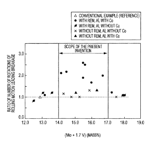
Fig. 3 shows the obtained results in terms of the
relationship between the ratio of the number of rotations of
rolling motion leading breakage and the amount of (Mo +
1.7V) (mass%). Fig. 3 shows the case where the roll surface
layer material contains, on a mass% basis, C: 2.1% to 3.1%,
Si: 0.3% to 0.7%, Mn: 0.3% to 1.0%, Nb: 0.7% to 1.4%, and
Co: 0% to 3.1%, further contains Cr in a range of 4.8% to
9.8%, Mo in a range of 3.8% to 6.9%, and V in a range of
4.9% to 7.3%, and contains Al and/or REM and the case where
the roll surface layer material contains, on a mass% basis,
C: 2.1% to 3.1%, Si: 0.3% to 0.7%, Mn: 0.3% to 1.0%, Nb:
0.7% to 1.4%, and Co: 0% to 3.1%, further contains Cr in a
range of 4.8% to 9.8%, Mo in a range of 3.8% to 6.9%, and V
in a range of 4.9% to 7.3%, and does not contain Al or REM.
Fig. 3 also shows the case where the roll surface layer
material does not contain Co in a separated manner.
As is clear from Fig. 3, when (Mo + 1.7V) is in the range of
14.0 to 17.0 and Al and/or REM is contained (*), the ratio
of the number of rotations of rolling motion leading
breakage is 1.5 or more, which is higher than the ratio of
the number of rotations of rolling motion leading breakage
in Conventional Example (A), and thus the resistance to hot
rolling fatigue is considerably improved. On the other hand,
CA 02850453 2014-03-28
- 11 -
when (Mo + 1.7V) is in the range of 14.0 to 17.0 but Al or
REM is not contained (x), a significant increase in the
ratio of the number of rotations of rolling motion leading
breakage is not observed.
[0019]
The present invention has been completed on the basis
of the above findings with further studies. That is, the
gist of the present invention is as follows.
[0020]
(1) A roll surface layer material produced by
centrifugal casting for a hot rolling mill has excellent
fatigue resistance and is used for a centrifugal cast roll
for a hot rolling mill, the roll surface layer material
having a composition including, on a mass% basis, C: 2.3% to
2.9%, Si: 0.2% to 0.8%, Mn: 0.2% to 1.0%, Cr: 5.0% to 7.5%,
Mo: 4.4% to 6.5%, V: 5.3% to 7.0%, Nb: 0.6% to 1.5%, and Co:
0.1% to 4.0% so as to satisfy formula (1) below,
14.0 (Mo + 1.7V) 17.0 -=- (1)
(where Mo represents a content (mass%) of Mo and V
represents a content (mass%) of V); and
further including Al: 0.001% to 0.03% and/or REM: 0.001% to
0.03%, with the balance being Fe and incidental impurities.
[0021]
(2) In (1), a centrifugal cast roll for a hot rolling
mill has excellent fatigue resistance and includes a surface
CA 02850453 2016-10-14
- 12 -
layer and an internal layer integrally welded to the
surface layer, the surface layer having an area fraction of
carbides of 13% to 20% and the roll surface layer
comprising a composition including, on a mass% basis, C:
2.3% to 2.9%, Si: 0.2% to 0.8%, Mn: 0.2% to 1.0%, Cr: 5.0%
to 7.5%, Mo: 4.4% to 6.5%, V: 5.3% to 7.0%, Nb: 0.6% to
1.5%, and Co: 0.1% to 4.0%, so as to satisfy formula (1)
below and further including Al: 0.001% to 0.03% and/or REM:
0.001% to 0.03%, with the balance being Fe and incidental
impurities,
14.0 (Mo + 1.7V) 17.0 ... (1)
where Mo represents a content (mass%) of Mo and V
represents a content (mass%) of V.
Advantageous Effects of Invention
[0022]
According to the present invention, a roll surface
layer material having both high compression 0.2% proof
strength and excellent resistance to hot rolling fatigue
can be provided and a high-performance centrifugal cast
roll for a hot rolling mill with considerably improved
fatigue resistance can be easily produced at low cost,
which achieves significant industrial advantages. In the
centrifugal cast roll for a hot rolling mill according to
the present invention, the fatigue resistance is
considerably improved and the damage to a roll surface such
as wear, surface deterioration, surface chipping, or
fatigue cracks can be considerably suppressed even in a
severe hot
CA 02850453 2014-03-28
- 13 -
rolling environment in which a high rolling load is applied.
According to the present invention, a significant
improvement in the surface quality of hot rolled steel
sheets, an improvement in the productivity of hot rolled
steel sheets, and an improvement in the life of rolls can be
achieved all together.
Brief Description of Drawings
[0023]
[Fig. 1] Fig. 1 is an explanatory view schematically
showing a structure of a tester used in a hot rolling
fatigue test.
[Fig. 2] Fig. 2 is an explanatory view schematically
showing the shape and size of a notch formed in a peripheral
surface of a test specimen for a hot rolling fatigue test
(fatigue test specimen) used in Examples.
[Fig. 3] Fig. 3 is a graph showing the influence of REM
and/or Al on the relationship between the ratio of the
number of rotations of rolling motion leading breakage and
the (Mo + 1.7V) amount in the hot rolling fatigue test.
Description of Embodiments
[0024]
A roll surface layer material of the present invention
is made by centrifugal casting and can be directly used for
ring rolls and sleeve rolls. The roll surface layer
material is applied as a surface layer material of hot
CA 02850453 2014-03-28
- 14 -
rolling mill composite roll suitable for hot finish rolling.
The hot rolling mill composite roll of the present invention
includes a surface layer made by centrifugal casting and an
internal layer that is integrally welded to the surface
layer. An intermediate layer may be disposed between the
surface layer and the internal layer. In other words, the
hot rolling mill composite roll may include, instead of the
internal layer integrally welded to the surface layer, an
intermediate layer integrally welded to the surface layer
and an internal layer integrally welded to the intermediate
layer. The internal layer is preferably made by a static
casting method. In the present invention, the compositions
of the internal layer and intermediate layer are not
particularly limited, but the internal layer is preferably
composed of spherical graphitic cast iron and the
intermediate layer is composed of a high carbon material
containing C: 1.5 to 3 mass%.
[0025]
The reasons for limiting the composition of the roll
surface layer material (surface layer) will be described.
Hereinafter, mass% is simply expressed as % unless otherwise
specified.
[0026] C: 2.3% to 2.9%
C dissolves into a matrix and thus increases the
hardness of the matrix and also bonds to a carbide-forming
CA 02850453 2014-03-28
- 15 -
element and thus forms a hard carbide, thereby improving the
wear resistance of the roll surface layer material. The
amount of an eutectic carbide varies depending on the C
content. The eutectic carbide affects the rolling
characteristics. Therefore, at a C content of less than
2.3%, an insufficiently small amount of the eutectic carbide
increases the friction force during rolling and causes
unstable rolling, and also the compression 0.2% proof
strength of the roll surface layer material decreases. On
the other hand, at a C content exceeding 2.9%, the amount of
the eutectic carbide excessively increases, the roll surface
layer member becomes hard and brittle, the formation and
growth of fatigue cracks are facilitated, and the fatigue
resistance degrades. Accordingly, the C content is limited
to the range of 2.3% to 2.9%.
[0027] Si: 0.2% to 0.8%
Si is an element that serves as a deoxidizer agent and
that improves the castability of molten metal. To achieve
such effects, 0.2% or more of Si needs to be contained. On
the other hand, at a Si content exceeding 0.8%, the effects
are saturated and effects corresponding to the content are
not to be expected, which is economically disadvantageous.
Accordingly, the Si content is limited to 0.2% to 0.8%.
[0028] Mn: 0.2% to 1.0%
Mn is an element that fixes S in the form of MnS,
CA 02850453 2014-03-28
- 16 -
thereby rendering S harmless and that partly dissolves into
a matrix, thereby improving the hardenability. To achieve
such effects, 0.2% or more of Mn needs to be contained. At
a Mn content exceeding 1.0%, the effects are saturated and
effects corresponding to the content are not to be expected,
and furthermore the material may become brittle.
Accordingly, the Mn content is limited to 0.2% to 1.0%.
[0029] Cr: 5.0% to 7.5%
Cr is an element that bonds to C and mainly forms an
eutectic carbide, thereby improving the wear resistance and
that decreases the friction force with a steel sheet during
rolling and thus reduces the damage to a roll surface,
thereby stabilizing the rolling. To achieve such effects,
5.0% or more of Cr needs to be contained. At a Cr content
exceeding 7.5%, the amount of a hard and brittle eutectic
carbide excessively increases, which degrades the fatigue
resistance. Accordingly, the Cr content is limited to the
range of 5.0% to 7.5%.
[0030] Mo: 4.4% to 6.5%
Mo is an element that bonds to C and forms a hard
carbide, thereby improving the wear resistance. Mo is also
an element that dissolves into a hard MC carbide in which V
and Nb bond to C, thereby reinforcing the carbide and that
also dissolves into an eutectic carbide, thereby increasing
the fracture resistance of the carbides. Through such
CA 02850453 2014-03-28
- 17 -
actions, Mo improves the wear resistance and fatigue
resistance of the roll surface layer member. To achieve
such effects, 4.4% or more of Mo needs to be contained. At
a Mo content exceeding 6.5%, a hard and brittle carbide
mainly composed of Mo is formed. This degrades the
resistance to hot rolling fatigue, which degrades the
fatigue resistance. Accordingly, the Mo content is limited
to the range of 4.4% to 6.5%.
[0031] V: 5.3% to 7.0%
V is an important element in the present invention
because V imparts both wear resistance and fatigue
resistance required for a roll. V forms an extremely hard
carbide (MC carbide) and thus improves the wear resistance
and also effectively divides and disperses/crystallizes an
eutectic carbide. V is also an element that improves the
resistance to hot rolling fatigue, thereby considerably
improving the fatigue resistance of the roll surface layer
material. Such effects are significantly achieved at a V
content of 5.3% or more. However, at a V content exceeding
7.0%, a coarse MC carbide is formed and the centrifugal
casting segregation of the MC carbide is facilitated, which
destabilizes various characteristics of a rolling mill roll.
Accordingly, the V content is limited to the range of 5.3%
to 7.0%.
[0032] Nb: 0.6% to 1.5%
CA 02850453 2014-03-28
- 18 -
Nb dissolves into an MC carbide and reinforces the MC
carbide and thus increases the fracture resistance of the MC
carbide, thereby further improving the wear resistance, in
particular, the fatigue resistance. When both Nb and Mo are
dissolved into a carbide, the wear resistance and the
fatigue resistance are considerably improved. Nb is also an
element that facilitates the division of an eutectic carbide
and suppresses the fracture of the eutectic carbide, thereby
improving the fatigue resistance of the roll surface layer
material. Nb also suppresses the segregation of the MC
carbide during centrifugal casting. Such effects are
significantly achieved at a Nb content of 0.6% or more.
However, at a Nb content exceeding 1.5%, the growth of the
MC carbide in a molten metal is facilitated and the carbide
segregation during centrifugal casting is promoted.
Accordingly, the Nb content is limited to the range of 0.6%
to 1.5%.
[0033] Co: 0.1% to 4.0%
Co is an element that dissolves into a matrix and
reinforces the matrix, in particular, at high temperature,
thereby improving the fatigue resistance. To achieve such
effects, 0.1% or more of Co needs to be contained. On the
other hand, at a Co content exceeding 4.0%, the effects are
saturated and effects corresponding to the content are not
to be expected, which is economically disadvantageous.
CA 02850453 2014-03-28
- 19 -
Accordingly, the Co content is limited to the range of 0.1%
to 4.0%. The Co content is preferably 0.2% to 3.0%.
[0034]
In the present invention, Mo and V are contained in the
above-described ranges and furthermore are contained so as
to satisfy formula (1) below.
14.0 (Mo + 1.7V) 17.0 === (1)
(where Mo represents a content (mass%) of Mo and V
represents a content (mass%) of V)
[0035]
As shown in Fig. 3, when Al and/or REM is contained, by
adding Mo and V so that (Mo + 1.7V) satisfies the above
formula (1), the number of rotations of rolling motion
leading breakage is considerably increased compared with the
reference (Conventional Example) and thus the resistance to
hot rolling fatigue is considerably improved. The (Mo +
1.7V) is an important factor for improving the resistance to
hot rolling fatigue. Only when the (Mo + 1.7V) is adjusted
to be in the range of 14.0 to 17.0, excellent resistance to
hot rolling fatigue can be maintained. In the case where
the (Mo + 1.7V) is outside the range of 14.0 to 17.0, even
if Al and/or REM is contained, the resistance to hot rolling
fatigue degrades. Accordingly, in the present invention,
the contents of Mo and V are adjusted so as to satisfy the
formula (1).
CA 02850453 2014-03-28
- 20 -
[0036]
In the present invention, the contents of Mo and V are
adjusted so as to satisfy the formula (1) and Al and/or REM
is essentially contained.
[0037] Al: 0.001% to 0.03% and/or REM: 0.001% to 0.03%
Only when Mo and V are contained so as to satisfy the
formula (1), Al and/or REM considerably improves the
resistance to hot rolling fatigue as shown in Fig. 3. To
achieve such effects, 0.001% or more of each of Al and REM
needs to be contained. On the other hand, even if more than
0.03% of each of Al and REM is contained, the effects are
saturated and the castability is degraded by, for example,
bubble formation and a decrease in fluidity of molten steel.
Accordingly, the contents of Al and/or REM are limited to
the range of Al: 0.001% to 0.03% and/or REM: 0.001% to 0.03%.
[0038]
The balance other than the above components is Fe and
incidental impurities.
Examples of the incidental impurities include P: 0.05% or
less, S: 0.05% or less, and N: 0.06% or less. P segregates
in a grain boundary and degrades the quality of a material.
Therefore, in the present invention, the P content is
desirably as low as possible, but a P content of 0.05% or
less is permissible. S is present in the form of a sulfide
inclusion and degrades the quality of a material. Therefore,
CA 02850453 2014-03-28
- 21 -
the S content is preferably as low as possible, but a S
content of 0.05% or less is permissible. N mixes in a
concentration of about 0.06% or less through ordinary
dissolution, but such a concentration does not affect the
advantageous effects of the present invention. The N
content is preferably less than 0.05% because N may form
defects at a boundary between the surface layer and the
intermediate layer or between the surface layer and the
internal layer of a composite roll.
[0039]
In the roll surface layer material of the present
invention, large amounts of Cr, V, Mo, and the like are
contained and an extremely hard carbide (MC carbide) and an
eutectic carbide are dispersed, whereby a desired hardness,
a desired wear resistance, and the like are achieved. If
the carbides have an area fraction of less than 13%, such a
desired hardness, wear resistance, and the like are not
easily achieved. On the other hand, if the carbides have an
area fraction of more than 20%, the roll material may become
brittle. Accordingly, the area fraction of the carbides is
preferably limited to the range of 13% to 20%.
[0040]
A preferred method for producing a hot rolling mill
composite roll of the present invention will now be
described.
CA 02850453 2014-03-28
- 22 -
In the present invention, the method for producing a roll
surface layer member is a centrifugal casting method, which
is performed with a low energy cost.
[0041]
A molten metal having the above roll surface layer
material composition is poured into a rotatable mold whose
internal surface is coated with a refractory mainly composed
of zircon so that a predetermined wall thickness is achieved.
The molten metal is then subjected to centrifugal casting.
In the case where an intermediate layer is formed, the
intermediate layer is preferably formed by the following
method. During the solidification of the roll surface layer
member or after the complete solidification of the roll
surface layer member, a molten metal having an intermediate
layer composition is poured into the mold while rotating the
mold and then cast by centrifugal casting. After the
surface layer or the intermediate layer is completely
solidified, preferably, the rotation of the mold is stopped
and the mold is put in a standing position, and then an
internal layer material is cast by static casting to obtain
a composite roll. Thus, the inner surface of the roll
surface layer member is remelted to form a composite roll in
which the surface layer and the internal layer are
integrally welded or a composite roll in which the surface
layer and the intermediate layer are integrally welded and
CA 02850453 2014-03-28
- 23 -
the intermediate layer and the internal layer are integrally
welded.
[0042]
The internal layer subjected to static casting is
preferably composed of, for example, spherical graphitic
cast iron or compacted vermicular graphitic cast iron (CV
cast iron) having excellent castability and mechanical
properties. Since the centrifugal cast roll includes the
surface layer and the internal layer integrally welded to
each other, about 1% to 8% of surface layer components mix
in the internal layer. Cr, V, and the like contained in the
surface layer member are powerful carbide-forming elements.
The mixing of these elements in the internal layer causes
the internal layer to be brittle. Accordingly, the
proportion of the surface layer components mixed in the
internal layer is preferably decreased to less than 6%.
[0043]
In the case where the intermediate layer is formed, for
example, graphitic steel, high carbon steel, or hypoeutectic
cast iron is preferably used for the intermediate layer
material. The intermediate layer and the surface layer are
integrally welded in a similar manner, and about 10% or more
and 90% or less of the surface layer components mix in the
intermediate layer. To suppress the amount of the surface
layer components mixed in the internal layer, it is
CA 02850453 2014-03-28
- 24 -
important to reduce the amount of the surface layer
components mixed in the intermediate layer as much as
possible.
[0044]
The hot rolling mill composite roll of the present
invention is preferably heat treated after the casting. The
heat treatment preferably includes performing a process in
which the composite roll is heated to 950 C to 1150 C and
cooled by air cooling or air blast cooling and performing,
at least once, a process in which the composite roll is
heated and held at 450 C to 600 C and then cooled.
[0045]
The hardness of the hot rolling mill composite roll of
the present invention is preferably 79 to 88 HS and more
preferably 80 to 86 HS. To stably achieve the hardness, it
is recommended to adjust the heat treatment after the
casting.
EXAMPLES
[0046]
A molten metal having a roll surface layer material
composition shown in Table 1 was melted in a high frequency
furnace and cast into a ring-shaped test member (ring roll;
outer diameter: 250 mm4), wall thickness: 55 mm) by a
centrifugal casting method. The pouring temperature was
1380 C to 1450 C and the centrifugal force, expressed as
CA 02850453 2014-03-28
- 25 -
multiples of gravity, was 176 G. After the casting, a
quenching treatment in which the ring-shaped test member was
reheated to a quenching temperature of 1050 C and cooled by
air cooling and a tempering treatment in which the ring-
shaped test member was heated and held at a tempering
temperature of 450 C to 600 C and cooled were performed to
adjust the hardness to be 78 to 84 HS.
[0047]
A ring-shaped test member (ring roll) having a
composition of a high-speed steel roll surface layer member
made by centrifugal casting and used for a hot finish
rolling mill (on a mass% basis, 2.1% 0-0.4% Si-0.4% Mn-6.3%
Cr-4.2% Mo-5.1% V-0.1% Nb-balance being Fe and incidental
impurities) was cast by a centrifugal casting method and
heat treated in the same manner to obtain a reference member
(Conventional Example).
[0048]
A hardness test specimen, a compression test specimen,
a hot rolling fatigue test specimen, and a test specimen for
microstructure observation were taken from the obtained
ring-shaped test member to perform a hardness test, a
compression test, a hot rolling fatigue test, and a
microstructure observation test. The test methods are as
follows.
[0049]
CA 02850453 2014-03-28
- 26 -
(1) Hardness test
The Vickers hardness HV 50 of the prepared hardness
test specimen was measured with a Vickers hardness tester
(testing force: 50 kgf (490 kN)) in conformity with JIS Z
2244, and the Vickers hardness HV 50 was converted into
Shore hardness HS using a JIS conversion table. The Vickers
hardness HV 50 was measured at 10 positions for each
specimen. The maximum value and the minimum value were
taken away and the arithmetic mean was calculated. The
arithmetic mean was defined as the hardness of the test
member.
[0050]
(2) Compression test
A compression test was performed on the prepared
compression test specimen (diameter 10 mm(I) x length 20 mm)
at room temperature. The number of repetitions was set to
be two. In the compression test, a strain gage was attached
to the central portion of the compression test specimen and
a stress-strain curve was obtained. The 0.2% proof strength
was read from the obtained stress-strain curve. The average
of 0.2% proof strengths of two test specimens was defined as
the 0.2% proof strength of each test member.
[0051]
(3) Hot rolling fatigue test
A hot rolling fatigue test specimen (outer diameter: 60
CA 02850453 2014-03-28
- 27 -
mm(1), wall thickness: 10 mm, chamfered) having a shape shown
in Fig. 2 was taken from the obtained ring-shaped test
member. In the hot rolling fatigue test specimen, a notch
(depth t: 1.2 mm, length L in a circumferential direction:
0.8 mm) shown in Fig. 2 was formed at two positions
(positions 180 apart from each other) of a peripheral
surface of the specimen by an electro-discharge (wire cut)
method that uses a wire with 0.20 mm. As shown in Fig. 1,
the hot rolling fatigue test was conducted by a two-disc
slipping/rolling method that uses a test specimen and an
opposing specimen. The test specimen was rotated at 700 rpm
while being cooled with water. An opposing specimen
(material: S45C, outer diameter: 190 mm(I), width 15 mm,
chamfered) heated to 790 C was brought into contact with the
rotating test specimen while applying pressure at a ,load of
980 N and the rolling motion was performed at a slip factor
of 10%. The rolling motion was performed until the two
notches formed in the hot rolling fatigue test specimen were
broken. The number of rotations of rolling motion until
each notch was broken was determined, and the average of the
numbers of rotations of rolling motion was defined as the
number of rotations of rolling motion leading breakage. The
number of rotations of rolling motion leading breakage in
Conventional Example was assumed to be a reference (1.0),
and the ratio of the number of rotations of rolling motion
CA 02850453 2014-03-28
- 28 -
leading breakage of each ring-shaped test member to the
number of rotations of rolling motion leading breakage in
Conventional Example, that is, (the number of rotations of
rolling motion leading breakage of each ring-shaped test
member)/(the number of rotations of rolling motion in
Conventional Example) was calculated and used as an index of
fatigue resistance. When the ratio of the numbers of
rotations of rolling motion leading breakage was more than
1.5, the ring-shaped test member was evaluated to have
excellent fatigue resistance.
[0052]
(4) Microstructure observation test
The prepared test specimen for microstructure
observation was polished and subjected to nital corrosion.
The microstructure was observed using an image analyzer with
an optical microscope at a magnification of 50 times. The
obtained image was subjected to binary conversion to measure
the area fraction of a carbide. The area fraction was
treated as the amount of a carbide of each test member.
Table 2 shows the results.
[0053]
[Table 1]
- 29 -
Table 1
Test Chemical composition (mass%)
member
Mo + Satisfaction of Remarks
No. C Si Mn P S Cr Mo V Nb Co REM Al
1.7V
formula (1)*
A 2.5 0.5 0.4 0.02 0.008 6.2 5.3 6 0.9 2.1
0.023 0.015 15.5 Yes Invention Example
B 2.6 0.3 0.5 0.025 0.009 6.3 6.3 5.7
1.1 0.3 - 0.012 16 Yes Invention Example
C 2.5 0.4 0.4 0.028 0.01 7.5 5.1 5.5 1.3
3.1 0.01 - 14.5 Yes Invention Example
,
D 2.7 0.4 0.3 0.015 0.008 7.1 4.6 6.4
1 0.9 - 0.013 15.5 Yes Invention Example
E 2.7 0.6 0.5 0.022 0.007 7 5.4 6
1.2 1.3 0.007 0.006 15.6 Yes Invention Example
F 2.4 0.7 1 0.03 0.01 6.7 4.5 5.7 1.4 2
0.006 0.015 , 14.2 Yes Invention Example
G 2.8 0.4 0.8 0.019 0.009 5.1 5.6
6.5 0.8 0.4 0.004 0.018 16.7 Yes Invention
Example n
H 2.3 0.4 0.5 0.018 0.01 7.2 iv 4.8 4.9
1.2 - - 0.005 13.1 No
Comparative Example 0
_
.
co
co
I J. 0.3 0.4 0.019 0.008 6 6.1 6.9 1.2 -
0.021 - 17.9 No Comparative Example 0
a,
co
J 2.6 0.4 0.4 0.019 0.009 7.9 _ 4.1 5.6 1.1 -
- 0.01 13.6 No Comparative Example co
iv
K 3.1 0.4 0.4 0.024 0.009 7.3 5.6 7.3
1.1 - 0.004 0.006 18 No Comparative Example 0
H
, .
a,
1
L 2.9 0.5 0.9 0.022 0.008 7.4 5.6 5.4
0.7- 0.0004 14.8 Yes Comparative Example
-
0
u.)
1
M 2.8 0.4 0.4 0.017 0.008 6.8 5.5 6.1
1 -- - 15.9 Yes Comparative Example
iv
co
N 2.6 0.6 0.6 0.021 0.009 6.5 4.8 5.6
1.1 -- 14.3 Yes Comparative Example
O 2.7 0.4 0.5 0.023 0.008 6.9 5.5 5.8
1.1 -- - 15.3 Yes Comparative Example
P 2A 0.4 0.4 0.026 0.011 6.3 4.2 5.1
OA- - - 12.9 No Conventional Example
. .
Q 2.7 0.3 0.3 0.021 0.009
9.8 6 5 1.3 -
_ -
_ -
14.5
Yes
Comparative Example
R 2.6 0.4 0.3 0.019 0.01 4.8 3.8 5.1 1
- - 0.011 12.5 No Comparative Example
S 2.7 0.3 0.3 0.018 0.008 7 6.9 6.2
1 -- - 17.5 No Comparative Example
_
T 2.5 0.5 0.6 0.018 0.008 7.1. 6 5.4 1
1.5 - - 15.2 Yes Comparative Example
U 2.7 0.4 0.5 0.025 0.01 7.3 5.7
6.4 1.1 2- 16.6 Yes , Comparative
Example
_
,
/ 2.6 0.6 0.4 0.028 0.008 7 4 5.5
1.2 1 0.007 0.015 13.4 No Comparative Example
W 2.5 0.5 0.5 0.018 0.006 6.9 6.9 6.2
0.9 1.5 0.009 0.018 17.4 No Comparative Example
Satisfaction of formula (1)* 14.0 (Mo + 1.7V) 17.0
Underlined items are outside the scope of the present invention.
CA 02850453 2014-03-28
- 30 -
[0054]
[Table 2]
Table 2
Amount of
Hardness Strength Fatigue resistance
carbide
Test
02
member .% proof
Ratio of number of Remarks
Area strength
No. HS rotations of rolling
fraction (%)
(M-Pa) motion leading breakage
A 17.6 82 2215 2.6 Invention Example
B 15.8 85 2263 1.7 Invention
Example
C 19 83 2145 2.2 Invention Example
D 18.3 81 2140 1.9 Invention
Example
E 16.5 84 2190 2.5 Invention
Example
F 14.9 80 2110 2.1 Invention Example
G 17 83 2142 2 Invention Example
H 18.3 83 1916 1.2
Comparative Example
I 11.2 82 1713 1.1
Comparative Example
J 17.5 84 1983 1.2
Comparative Example
K 22.7 84 1867 1.1
Comparative Example
L 24.2 82 1867 , 1
Comparative Example
M 16.7 83 1923 1.3 Comparative
Example
N 15.9 84 1996 1.2
Comparative Example
O 16.9 84 1196 1
Comparative Example
P 8.2 81 1823 1.0
(reference) Conventional Example
Q 23.5 82 1910 1.2
Comparative Example
R 13.6 82 1891 0.8 Comparative
Example
S 18.7 84 1872 1
Comparative Example
T 16.8 81 1885 1.2 Comparative
Example
U 17.1 80 1925 , 1.3 ,
Comparative Example
/ 18 83 1954 1.1 ,
Comparative Example
W 16.4 82 1863 1.2 Comparative
Example
Underlined items are outside the scope of the present invention.
[0055]
In Invention Examples, the number of rotations of
rolling motion leading breakage was increased to more than
1.5 times the number of rotations of rolling motion leading
CA 02850453 2014-03-28
- 31 -
breakage in Conventional Example (reference) and the
resistance to hot rolling fatigue was considerably improved.
Furthermore, the compression 0.2% proof strength was as high
as 2000 MPa or more. Therefore, in Invention Examples, roll
surface layer materials having excellent fatigue resistance
and having both high compression 0.2% proof strength and
excellent resistance to hot rolling fatigue were provided.
In Comparative Examples which are outside the scope of the
present invention, the compression 0.2% proof strength was
degraded, the resistance to hot rolling fatigue was degraded,
or both of them were degraded.