Note: Descriptions are shown in the official language in which they were submitted.
CA 02850592 2014-03-31
WO 2013/045954
PCT/GB2012/052427
Detection Device
The present invention relates to a detection device, more particularly to a
device for
the detection of an open and unattended closure to an enclosure.
It is important in some environments to ensure that doors into enclosures,
such as
cupboards, cabinets, boxes, drawers, or rooms, are not left open and
unattended. For
example, in the medical environment, drug cupboards and drug trolleys need to
be
used unimpeded for periods of time by staff but must not be left accessible
without a
member of staff present. On a busy hospital ward, it is very easy for a drug
cupboard
or drug trolley to be accidently left open and unattended and this has led to
theft of
controlled substances. This is highly undesirable and a balance has to be
found
between the practical use of a drug cupboard or drug trolley and securing the
contents of these enclosures.
There are several types of device that have been used to secure doors and
entranceways, however, most of these devices relate to unauthorised access
rather
than ensuring that doors are not left open and unattended. For example, US
5,281,952 describes a device that allows an authorised person to determine if
an
unauthorised person has accessed a room. The device disclosed therein is
triggered
by light and, if an unauthorised user enters the room, the device will emit an
audible
alarm for a pre-determined amount of time. This device is one of many devices
that
detect light, movement, or temperature changes to determine if a door has been
opened. However, this type of alarm is not suitable in every environment and
for
every situation. As stated above, in the medical environment, drug cupboards
and
drug trolleys need to be used unimpeded for periods of time by staff on
hospital
wards and, in such circumstances, an alarm that sounds constantly when the
door is
opened is highly undesirable.
Another approach is described in GB 2283603, where the device disclosed
therein
consists of an alarm unit and a magnet. When the alarm unit and magnet are
separated for more than ten seconds, the alarm unit emits a sound. Again, this
is not
suitable in many environments and this approach is not useful for an enclosure
that
needs to be used unimpeded for potentially long periods of time.
CA 02850592 2014-03-31
WO 2013/045954
PCT/GB2012/052427
Yet another example is a refrigerator alarm. Many refrigerators, for example
by the
Samsung group, have an alarm which is time based to remind users to close the
door
if left open for a predetermined time. This is helpful under most
circumstances
however can cause annoyance at times when the user wishes to leave the door
open
for a prolonged time, for example whilst transfering a weekly load of
provisions into
the refrigerator.
One device specifically designed to secure drug cabinets is the Controlled
Drug
Cabinet Alarm as sold by the FPD Group. This alarm is activated when the
cabinet
door is unlocked and an external red warning light is displayed to alert a
user. After a
pre-determined period of time a warning alarm or beep sounds. A disadvantage
of
this device is that the alarm will sound even if the user still requires the
cabinet door
to be open. Also, in order to turn off the alarm, the cabinet door would have
to be
closed which can lead to an inefficient use of time for the user if they still
require
access to the cabinet and would need to immediately reopen the doors.
Another device that calls a user's attention to an open drugs cabinet is the
Nurse
Station Unit made by Wandsworth. This device has a light provided on a control
panel which indicates when the door of a drug cabinet has been opened. This
could
easily be missed by a busy nurse and also has the disadvantage of not
indicating if
the drugs cabinet is actually in use.
It is an object of the present invention to overcome the above-mentioned
disadvantages of the prior art.
According to a first aspect of the invention, there is provided a device for
the
detection of an open and unattended closure of an enclosure to prevent theft,
comprising: a detector adapted to detect if the closure is open and a detector
adapted
to detect if the closure is unattended, the detectors being operably connected
to an
effector adapted to alert a user to the open and unattended condition of the
closure.
This device, unlike the prior art, has the advantage that it can detect that
the
enclosure is both open and unattended. Therefore, the device will only alert
the user
if both conditions apply and not just after a pre-determined time period has
elapsed.
2
CA 02850592 2014-03-31
WO 2013/045954
PCT/GB2012/052427
The device of the present invention is particularly useful in environments
where
alarms are intrusive and undesirable.
Preferably, the detector adapted to detect if the closure is open is also
adapted to turn
the device on upon opening of the closure and off when the closure is returned
to a
shut position. This allows for an efficient use of power to the device and
assists in
ensuring that the device will only be operational when required.
Preferably, the detector adapted to detect if the closure is unattended is
also adapted
to turn the device off for a pre-determined period of time when actuated by
the
proximity of a user, or to actuate the effector if the proximity of a user is
not
detected. This detector also allows for efficient use of power as the device
is
switched off after the detector has been triggered. Additionally, as the
detector turns
the device off when it is activated and only triggers the effector when is not
activated, it provides a system which will only trigger the alarm if the
device is
unattended.
Preferably, the effector adapted to alert a user to the open and unattended
condition
of the closure is also adapted to deactivate if the detector adapted to detect
if the
closure is open detects that the closure has been returned to a closed
position, or if
the detector adapted to detect if the closure is unattended detects the
proximity of a
user. Once the alarm has sounded, either the closure being closed or a user
accessing
the opening of the enclosure can reset the device. Therefore, if the alarm is
triggered,
the user will be reminded to close the open closure or, if the enclosure is
still in use,
simply return to the enclosure. In a preferred embodiment, the device of the
present
invention continually monitors and detects both light and movement. In one
embodiment, the detection of movement causes the device to be switched off and
the
timer to be reset for a pre-determined period of time. In another embodiment,
the
activated timer may be reset, for example, after detecting movement. In this
embodiment the timer will be continuously reset provided there is movement in
a
predetermined proximity to the closure.
Preferably, the length of the pre-determined period of time is variable by a
user. The
ability to alter the time period in which the device is switched off after the
detector
3
CA 02850592 2014-03-31
WO 2013/045954
PCT/GB2012/052427
adapted to detect if the closure has been opened, allows for flexibility
within the
system. For example, if the device is fitted to a drug trolley or drug
cabinet, then the
time period may advantageously be shorter, for example, when used in smaller
hospital wards and longer, for example, when used in larger hospital wards. In
a
preferred embodiment, the predeteimined period of time is between one and four
minutes, and preferably two minutes.
Preferably, the detector adapted to detect if the closure is open is a light
detector
adapted to activate by the presence of light and deactivate in darkness. Light
detectors have the advantage that they are readily able to determine if the
enclosure
has been opened and are readily available, cheap to manufacture and have a
proven
reliability.
Preferably, the detector adapted to detect if the closure is open is a
magnetic switch
adapted to activate by the opening of the closure and deactivate when the
closure is
returned to a closed position. Advantageously, the use of a magnetic switch
ensures
that the device is only activated when the closure is open. Additionally, a
magnetic
switch may advantageously function in all environments without further
adaption, for
example, such a switch may be used in low light environments.
Preferably, the detector adapted to detect if the closure is open comprises
both a
magnetic switch and a light detector which are adapted to activate in series
or
parallel upon opening of the closure, and deactivate when the closure is
returned to a
shut position. This combination advantageously allows for all eventualities
and
creates a system that ensures that the device is activated when the closure is
open.
Preferably, the detector adapted to detect if the closure is open is adapted
to activate
and deactivate by accessing a manual or electronic lock. This provides an
efficient
way of determining whether an enclosure is secure. If the device were linked
to the
.. lock of an enclosure, then the device would be activated even if the
closure was not
fully opened.
Preferably, the detector adapted to detect if the closure is unattended is a
passive
infrared proximity sensor. Advantageously, the use of a proximity sensor
detects the
4
CA 02850592 2014-03-31
WO 2013/045954
PCT/GB2012/052427
movement of a user as they access the opening to the enclosure and therefore
detects
if the closure is attended or unattended.
Preferably, the range of the proximity sensor can be varied. Varying the range
by
which the proximity sensor can detect movement in this manner has the
advantage
that it allows the user to alter the sensitivity of the device. In certain
environments, it
may be advantageous to ensure that the sensor is not activated by a passer by
and is
only activated by someone accessing the opening of the enclosure. In an
alternative
situation, it may be advantageous for a user not to be required to fully
return to the
opening of the enclosure in order to prevent triggering of the alarm.
Preferably, the effector adapted to alert a user to the open and unattended
condition
of the closure is an audio alarm. Advantageously, an audio alarm is readily
able to
alert a user to the open and unattended closure and may do so even if the
enclosure is
not in the line of sight of the user.
Preferably, the effector adapted to alert a user to the open and unattended
condition
of the closure is a visual alarm. The use of such a visual alarm is highly
advantageous as it may alert a user in environments where sound would be
undesirable.
Preferably, the effector adapted to alert a user to the open and unattended
condition
of the closure is both an audio and visual alarm. The use of both an audio and
visual
alarm would have the advantage of being much more likely to alert a user to
the open
and unattended condition of the closure.
Preferably, the effector adapted to alert a user to the open and unattended
condition
of the closure remotely activates an alarm. In this embodiment the effector
can
trigger an alarm that is not located on the device. This is advantageous in
environments which have a central area which is constantly manned, where the
alarm
would be noticed and acted upon immediately.
Preferably, once the effector adapted to alert a user to the open and
unattended
condition of the closure is activated it produces an intermittent crescendo
alarm
5
CA 02850592 2014-03-31
WO 2013/045954
PCT/GB2012/052427
between a minimum and maximum setting. This type of alarm is as unobtrusive as
possible and is advantageous in environments where an alarm would be
undesirable.
Preferably, the minimum and maximum settings of the device are variable. This
is
advantageous as it provides flexibility and allows the settings of the device
to be
tailored to its environment.
Preferably, the effector adapted to alert a user to the open and unattended
condition
of the closure produces a continuous alarm after the maximum setting of the
.. crescendo alarm has been reached. This allows a user time to prevent the
full alarm
from triggering but also ensures that the users attention is drawn to the
enclosure
after a long period of unattendance.
Preferably, the effector adapted to alert a user to the open and unattended
condition
of the closure automatically closes the closure when activated. This is
advantageous
as the closure may be automatically returned to a shut position if the alarm
is
activated.
Preferably, the device further comprises a means for automatically locking the
closure when in a closed position. This feature has the advantage that it
allows the
closure to be automatically secured if the alarm is triggered.
Preferably, the effector adapted to alert a user to the open and unattended
condition
of the closure provides an alarm having a frequency of between 15 and 20 kHz.
In
some cases, such frequencies may not be heard by elderly patients who may
suffer
from an age-related loss of hearing. Advantageously, the frequency range of
the
alarm has the effect that that it will not disturb elderly patients, but will
be still heard
by and alert the younger medical staff.
Preferably, the device further comprises a video and/ or audio recording
system.
Preferably, deactivation of the detector adapted to detect if the closure is
unattended
activates the video and/ or audio recording system. In a preferred embodiment,
the
video and/ or audio recording system is external to the device such as a
closed circuit
camera used with closed circuit television (CCTV). This is advantageous as it
6
CA 02850592 2014-03-31
WO 2013/045954
PCT/GB2012/052427
provides the user with the facility to monitor the device from a remote
location and
to observe the device at a later time. In addition, it may allow the user to
view and
identify the person or persons who may have tampered with the device.
Preferably, the device further comprises a keyless operating system.
Advantageously,
such a keyless operating system adds an additional level of security to
prevent
unauthorised access.
Preferably, the device functions under normal conditions in the presence of a
keyless
authorisation pass and emits a continuous alarm at the maximum setting if the
closure is opened by a user without a keyless authorisation pass. As only
authorised
users carrying the keyless pass can approach the enclosure closure, this
feature would
deter potential unauthorised persons from approaching the closure of the
enclosure.
Preferably, the device functions under normal conditions in the presence of at
least
two keyless authorisation passes. It may be advantageous to ensure that the
contents
of an enclosure are not accessible unless two authorised people are present.
This
feature would ensure that only authorised individuals could properly access
the
contents of the enclosure.
Preferably, the device further comprises a tamper alarm system.
Advantageously,
such a tamper alarm may help to prevent the unauthorised deactivation or
removal of
the device.
Preferably, the tamper alarm system comprises light sensitive, physical or
magnetic
switches. These components have the advantage that they may be used to create
a
tamper alarm that is robust and cheap to manufacture.
Preferably, the invention further comprises a cradle for securing the device.
The use
of a cradle has the advantage that it secures the device to the enclosure and
prevents
the device from being removed from the enclosure by an unauthorised person.
Preferably, the detector adapted to detect if the closure is open is a
relative light
sensor for detecting opening of the closure in low light environments. A
relative light
7
67284-32
sensor would advantageously allow the device to work in low light level
environments.
Preferably, the closure is a closure to a drug cabinet or drug trolley,
Ensuring that the closure
of a drug cabinet and drug trolley is not left open and unattended can be
highly critical. Drugs
can be expensive to purchase and the theft of such drugs can lead to a high
economic burden
on hospitals. Also, there is the potential that the stolen (either controlled
or non-controlled)
drugs are taken in an unsafe manner that could lead to overdose or, in some
cases, even
fatality. In addition, the present invention advantageously reduces the
potential for the
tampering of drugs that may be stored within the cabinet or trolley.
According to one aspect of the present invention, there is provided a device
for the detection
of an open and unattended closure of an enclosure to prevent theft,
comprising: a detector
adapted to detect if the closure is open and a detector adapted to detect if
the closure is
unattended by detecting proximity of a user near the enclosure, the detectors
being operably
connected to an effector adapted to alert a user to the open and unattended
condition of the
closure, wherein the detector adapted to detect if the closure is open is also
adapted to turn the
device on upon opening of the closure and off when the closure is returned to
a shut position.
The present invention will now be described, by way of example only, with
reference to the
accompanying drawings, in which:
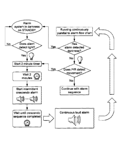
Figure 1 is a flow chart of the alarm system according to an embodiment of the
invention; and
Figures 2A, B, and C show a schematic representation of a circuit board for
the alarm system
of Figure 1.
Referring to the drawings, there is illustrated a device for the detection of
an open and
unattended closure of an enclosure to prevent theft, comprising: a detector
adapted to detect if
the closure is open (1) and a detector adapted to detect if the closure is
unattended (4), the
detectors being operably connected to an effector adapted to alert a user to
the open and
unattended condition of the closure (5).
8
CA 2850592 2018-08-09
67284-32
The alarm is on standby when the door to an enclosed space is closed. Upon
opening of the
door, the device detects light and movement. The detection of such light and
movement
causes a timer to be activated for a pre-determined period of time. After the
pre-determined
period of time has elapsed, an intermittent crescendo alarm is initiated,
which increases in
volume between a minimum and a maximum setting. Once the crescendo sequence is
complete, the device emits a continuous loud alarm. The alarm may be switched
off, either by
closing the door such that the device is in
8a
CA 2850592 2018-08-09
rt
CA 02850592 2014-03-31
WO 2013/045954
PCT/GB2012/052427
darkness, or by detecting movement, for example, near the proximity of the
door. In
the situation where the device detects movement, the device is turned off for
a pre-
determined period of time and the timer is reset. Advantageously, the device
of the
present invention continually monitors and detects light and movement. In one
embodiment, when the device is switched off and in the stand-by configuration,
the
detection of movement causes the timer to be reset. In one embodiment, the pre-
determined period of time in which the timer is activated is two minutes. In
another
embodiment, the activated timer may be reset, for example, after detecting
movement.
The skilled person would understand that the present invention may be embodied
in a
number of different ways. The following example illustrates one way in which
the
present invention can be successfully embodied.
Figures 2A, B and C show a schematic for the circuit board of one embodiment
of
the invention. In Figure 2A, the analogue response of the light sensitive
diode
(designated LED 1 and 2 on the schematic) (1) is converted into a digital
signal by
means of a voltage divider involving resistors R1, R15 and 16. As this is
under
power continuously, it is an extremely high resistance circuit to minimise
standby
current consumption and, as such, two light sensitive diodes in series have
been
incorporated to increase the sensitivity to light.
R1 is a variable resistor which will allow the light sensitivity to be
adjusted. This
circuit is an absolute light intensity switch, however, in another embodiment
the light
intensity switch could be converted to a relative light intensity switch by
placing a
further light sensitive diode between R1 and R15 and placing this on the
outside of
the enclosure. Neither this nor the second light sensitive diode designated
LED 2
have been included, and have been shorted across with a wire link.
The output of this potential divider has been fed to the input of a 40106 NOT
gate
(Ula). As such, as the light intensity on LED 1 rises, its resistance falls,
the potential
difference on the input of this gate rises and when it reaches its threshold
value, the
NOT gate flips state (from ON to OFF). A second NOT gate (Ulb) reverses this
state
such that it is off when the LED1 is in darkness.
9
CA 02850592 2014-03-31
WO 2013/045954
PCT/GB2012/052427
These NOT gates are Schmitt Trigger circuits and, as such, exhibit hysteresis
behaviour, which in practice means that the light intensity required to turn
on the
alarm is higher than that needed to turn it off. In other words, as cupboards
at night
are often opened in lighter areas and can be moved to darker areas, the alarm
may
still be active.
The output of Ulb is fed into a BC547 NPN transistor Q2. The output of this is
fed
into a 5v voltage regulator U3 such that a constant 5v output is delivered.
This is
suitable for the supply of the TTL PIR (Position Infrared) module (4), and
also
remains constant as the battery voltage begins to fall. The output of this is
used to
power the integrated circuits for the next part of the circuit (termed +5v on
the
schematic).
Figure 2B shows a timer circuit (2) based on 2 Schmitt Trigger NAND gates (U4a
and U4b) in conjunction with a capacitor (C7) and resistors R6 and R12 the
latter
components determining the time delay. The variable resistor R6 allows the
time
interval to be varied from a minimum which is determined by R12.
The timer (2) is activated when input B of U4a is momentarily connected to
earth
using transistor Q6 as a switch. This occurs when the circuit is powered up,
by means
of capacitor C18. One problem with this circuit is that retriggering (i.e.
restarting the
timer (2) before it has completed) is unreliable. Retriggering is enabled by
means of
transistor Q3 which discharges capacitor C7 through resistor R14. The output
is
inverted by U4c and is one of two inputs to the U4d. The PIR module (4) is
also
powered by the voltage regulator and the output of this is the second input to
U4d.
The output of the (4) module is also connected to the base of transistors Q3
and Q6
thus resetting the timer (2) as described above. As the PIR module (4) used
here is a
TTL device the output is tied to the 5v supply by means of a resistor (R7)
such that it
becomes compatible with the CMOS circuitry.
The output of U4d is used (via transistor Q5 as a switch) to power the next
part of the
circuit, which is the audio generating circuitry (5), as shown in Figure 2C.
This
output is termed 5v output on the schematic.
CA 02850592 2014-03-31
WO 2013/045954
PCT/GB2012/052427
The audio generating circuitry (5) is based around 3 Schmitt Trigger NOT gate
oscillators (U6a, U6b and U6f) which provide the rate of crescendo, the
interval of
beeps and the frequency of sound, respectively.
The first oscillator based around the U6a oscillator provides a square wave
with a
frequency adjustable via R2 from a minimum frequency determined by R. This
provides a clock input to the decade counter 4017 (U5). This arrangement
provides
the volume crescendo mechanism as each of the ten outputs connects to the next
resistor in a series of nine resistors. This means that, with each input pulse
from U6a
the output passes through a sequentially smaller resistance i.e., output 0
through 9
resistors output 1 through 8 and so on until it reaches the final output
(labelled out 9
on the schematic) where there is no resistor and hence the sound will be
loudest.
Ordinarily the sequential output would simply begin again, but to keep the
output on
this level this output is connected to the "clock enable" input which holds
the output
on that level.
To ensure the sequence always starts on the first output (labelled out 0 on
the
schematic) a capacitor (C15) provides a momentary pulse to the "reset"
connector
when this part of the circuit receives power. The circuit then creates a
stepwise
increasing voltage which is held at the maximum value.
To create a series of short beeps, a second oscillator (based around U6b)
creates a
further higher frequency (again adjustable) square wave which switches the
sound on
and off at the transistor Ql . In this embodiment, the sound may then be on
for an
equal time to that which it is off, i.e., a rather long beep which would be
shortened by
means of capacitor C14. The resulting exponentially decaying voltage is
converted
to a clean square wave by means of 2 NOT gates (U6c and U6d) in series. The
final
output (labelled "out 9", as described above) switches on the sound by means
of
transistor Q4.
To create the high frequency square wave required to drive the piezoelectric
transducer, the third oscillator (based on U6f as described above) delivers
this via
11
CA 02850592 2014-03-31
WO 2013/045954
PCT/GB2012/052427
transistor Q150. This sound is amplified via an inductor coil (L1) placed
across the
piezoelectric element.
A low battery indicator (3), as shown in Figure 2B, is present based on a
potential
divider of R40 and R41 placed across the output of transistor Q2. This means
that
this part of the circuit is only drawing current when the enclosure is open.
In one
embodiment, the circuit is designed to flash a light (LED 40). An alternative
embodiment comprises a circuit which is designed to have an intermittent beep
sounding.
This circuit is designed with maximum user simplicity in mind such that the
device
can simply be attached to a drug trolley without requiring further
accessories,
expense or training.
In a further embodiment, the device may be configured to trigger a closed
circuit
camera, either in the immediate vicinity of the device, or as part of a
system. In this
setting, the output of the timer (i.e. the output of U4c), which is connected
to
connector PL5, could be used via an optical isolator to trigger the camera.
In this embodiment, the camera would be activated for two minutes when the
drug
trolley is opened, and for a further two minutes every time the PIR detector
(4), as
shown in Figure 2B, detects movement. In other words, when someone approaching
the trolley inactivates the audible alarm, their presence will activate the
closed circuit
camera. In one embodiment, such a closed circuit camera may be used with
closed
.. circuit television (CCTV).
Similarly, in another embodiment, the system could be modified such that a
keyless
operating system could be incorporated such that proximity to a pass holder
would
cause the alarm to operate in a manner as described above. If an unauthorised
person
approached the device, an immediate loud and constant alarm will result. For
certain
situations, for example controlled drug cupboards where two practitioners are
required, the system may be configurable to require two proximity passes to
achieve
the normal functioning of the device.
12
CA 02850592 2014-03-31
WO 2013/045954
PCT/GB2012/052427
In yet another embodiment, a tamper alarm system may be integrated into the
device.
The tamper alarm system may consist of light sensitive, physical or magnetic
switches designed to elicit a constant maximal volume alarm if the unit is
removed or
tampered with. A cradle may be firmly attached to the wall of the drug cabinet
or
trolley into which the alann unit has been fitted in a removable manner, which
inactivates the tamper alarm when the device is in situ.
Additionally, in any of the stated embodiments, the device may have a
hardwired
battery, such that when this is exhausted a replacement device may easily be
slid into
place on the cradle. Since the cradle would be firmly adhered to the trolley,
if the
device has been removed, it will be very clear from the empty cradle.
20
30
13